con for the graph XY coordinates
Here you go
Tags: NI Software
Similar Questions
-
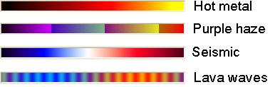
Table of standard color for the graph of the intensity
Hi all
I am trying to change the color table of a graph of intensity of some tables in color standard, such as 'rainbow', 'gray', 'seismic', 'waves of lava","hot metal","purple haze", etc.. I can't find not "Rainbow" and "grey" somewhere for the examples, but not others. I tried to generate these color tables myself using the example «...examples\general\graphs\intgraph.llb\Create Table.vi IntGraph color, but the result was far from good.
Can someone teach me how to generate these color tables? Thank you in advance.
Kind regards
Mario
Hi GerdW,
I'm not sure of the exact way to do it, but I did a simple vi based on your idea. The vi to retrieve the color table I want in the table format, subject me to load the bitmap file that contains only the color scale. Some raster color table constants are included in the VI for those in need. Please see the attachments and give me your comment.
Kind regards
Mario
-
Data for the graph economy waveform
Hello
I'm trying to collect the data of temperature with the attached VI. Everything works fine until I open the exported file that contains only the last point of the chart. I already had this problem and I think that it is quite common, but I can't find how to solve it.
Thank you very much for your help!
Here's what you do. The central loop is where you get several waveforms. You want to write each waveform in the output file, which means you want the wave form to write to the worksheet in the Central loop. Look at its inputs and outputs - put three of them, the file Path/New path, add to the file? and the header? on the shift registers. Initialize (wants to say wire the register shift outside the While loop) the path of the file to "data\test" (as you've already done), with the new path towards the "output" Shift Register Terminal. False (the default) of thread to add to the file? and true (if you want headers) to headers? On the side of the "output" of these two SHIFT registers, wire to 'Add to the file?' "True" and "False" to "Headers?
For the first time you run the intermediate loop, the file will be opened in a new file (since add to the file? is false) and a possibly written header. All subsequent calls will add data in the same file (because you wired "True" to add to the file on the output terminal) and no header.
And to get rid of the unnecessary frame at the end – data flow will be responsible for sequencing.
Bob Schor
-
Type of input data for the graph waveform
Waveform graphs do not change the type of input data according to the wire. When I create a new chart that is set to double data type and does not change what I connect to waveform, so I copy graphics to another VI for appropriate indication. But the graphics don't accept complex data. How can I change the type of input data?
The graphics in vi you have posted behave properly on my machine.
Change according to the type of data that connect you to them.
Maybe something wrong with your installation?
-
Coordinates of the cursor & Rectangle coordinates does not not to
Hello!
I actually paint a drawing a rectangle on xy graph using the mouse by clicking on the events and I need the contact information exactly the way it is extracted by cursor. The indicator of "coord2" & "cursor 0" should give me the same results. I need output of coord 2 as cursor 0 hope I managed to pass my point. Maybe I need to manipulate with scale. Check the attachment.
Sets,
I have attached a VI that will transform your mouse up and down the coordinates which are by default in pixels for the x - y coordinates. I also noticed that you could not make a rectangle when you started at the top left and ended at the bottom right, so I added a logic, so you can start and finish anywhere and have the rectangle belong.
I also noticed that when you draw the rectangle that the corners are drawn a little below and to the left of the cursor, that is the question you are trying really hard? I just looked in that a bit but could not understand why that was happening.
-
Hi, I have two decimal strings, each of them contains the numbers change over time. I want to plot them on the graph XY, a string for each axis. Can you show me how do?
This is not a formula, but a constant simple schema of a table complex. Wire remains, then do a right click of the terminal of the initializer of the feedback node and select "create constant. That should do it.

-
The search in a table 2d-coordinates for the point of click
I'm doing a VI that creates a layer of 2d points on an image imported (as pictured). These points are generated by a Subvi, which simply draws points over and over again (based on the 3 selections of initial angle). All the coordinates of the points are stored in a data feed that is sent to a registry change for other future functions. Each coordinate corresponds to an electrode, labeled 0-255, goes into the lines first (although that could change, but I guess it would be easy to change). Labels are created through 2 loops (as seen in diagram 1).
I would now like to click on a particular point and put it out in a different color, but also an indicator show me what electrode I clicked. I seem to be at a loss on how to do it! I need explore a table 2d-2 groups of the element, where she looks for the line first, then the corresponding column (or vice versa, it is not serious, but just for ease of understanding, let's say she is looking X first, where the columns first) and compare them to 2 elements (the mouse click coordinates).
Here's what I've done so far. I need to search for the function in the following way; If find X, look no further columns and select that particular column where the X was found and begins to look for the values Y and and then stops when the value of Y is. Once the two values are found, take these out of the loops and throw them in a cluster and the function of drawing lots.
Thank you!
p.s. in case anyone is wondering why I have the function "in the range" in there, it's so that the user does not have to be exact pixel
 this allows the user to click within 2 pixels of the coordinate of the point.
Hi Daniel!
What do you think of this approach?
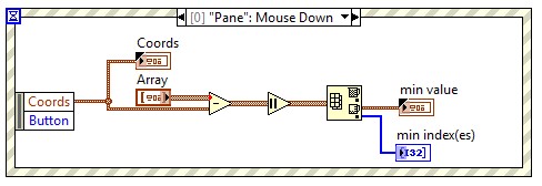
We subtract just the mouse coordinates in the coordinated range 2D (Array stores the coordinates of the points on the image), the absolute value and look for the minimum. X and y the selected point index is returned in minutes or the index. You can replicate the fuction "in range" by ensuring min value is not too high.
With regard to:
Andrew Valko
NOR Hungary
-
Two background colors for the same waveform graph
Hello guys!
I have a question for you: I am a new user of labview, so please be nice!

So here's the deal: I just created a thanks 4 thermocouple temperature registration program.
In real time, I then have a waveform graph 4 curves as soon as I start my program. And in my program, I had a button that allows me to record the temperature in a file for a period of time at a certain frequency.
So, what I have is: I got my chart of waveform with a black background for example, and once I pressed the button, the background color will be changed automatically to highlight the part of the graph where the record occurs, then the background will return to the black after finished recording. In this way, on the same graph, I could say that registration took place from here to there by looking at the graph. I have two different background on the same graph.
I don't know how to change the background of a chart using the property node, but is it possible to do what I want?
I hope I'm clear. Otherwise, feel free to ask me for more details... I might post my vi if necessary
See you soon
Well, I know this is not exactly what you want to do, but you can try the following.
Change the color of the line on the chart when recording occurs.
You could therefore have a red line, then press on save, then it turns blue, then back to red.
And when that is confusing since you have 4 different lines on the chart 1,
You can change to a red line and a dotted red line, for example.
Would that be acceptable? If so, I can show you how to do this.
-
Two indicators for the same graph.
How to connect the same indicators for the chart even if you have it in different tabs?
Looks like you want to use the same indicator in two different cases. It is not really possible, unless you want to use a local variable - which I would not recommend it. If you want something wire to the same flag from various cases, you need to place the flag outside the structure of the case, which makes a tunnel through the structure of the case.
In addition, it seems that you want to the same graph in two different tabs in a tab control. Why use different tabs if you want the same information? Maybe you could redesign your GUI?
But once again, as everyone said, share your code and it will be much easier for us to help :-)
-
Control the properties of the graph of a waveform for waveform table.
I'm to customize a waveform graph. I will have no problem using nodes property to define all the things I need to (color plot, the names of axes, etc...). My wave form is actually an array that contains the seven waveforms. The problem is that the property of the waveform graph node changes only trace, legend, etc. the first signal in the graph. They all have the chart perfectly together. However, my application requires the user to be able to select say signals 2, 5 and 7 of the table. When it does, it receives signals of 2, 5 and 7 on the chart, but the legend Watch reports 1, 2 and 3 and they draw in the colours of the signals 1, 2 and 3. Any suggestions on the update of the properties of several plots of a waveform graph?
Also when I want 1 signal trace a curve of waveform. When I want the signals from 2 to 7, I have to draw a second copy of the curve of waveform. For some reason any a waveform table chart cannot double as a unique waveform graph. Any ideas on that? Thanks in advance for your help.
To change the properties of other signals in the chart, you will need to set the ActivePlot property node before writing the color, the name of legend, etc... To display only the selected signals, you could do a couple different things.
(1) set the color of the signals that are not visible by transparency
(2) write NaN values to the curve of waveform of the signal that you do not want to display
-
GPS coordinates in the search for the card Module box
Can you put GPS coordinates in the search box of card module CC Lightroom? If so, what is the format? Support said it was for the names. I thought that I used to be able to do about 6-8 months ago.
You can put the lat/long coordinates in the map search box:

In my view, that he accepts all formats that Google agrees (although I have not tried all).
-
Data for the DB Oracle RDF graph modeling
I wonder how Oracle RDF graph DB modeling the attributes of the node or relationship? Suppose a node (dubject or object) is a person who has a lot of attriubtes, say, age, date of birth, ssn, address, etc., it seems RDF Oracle cannot Associate attriubtes to the node and instead it models simply each attribute as a node in the graph. It is common to include attributes in the graph database?
Hello
RDF (and offering of Oracle's RDF) allow generally associate any number of attributes that you need to the nodes in the graph. You are right in saying that these attributes are
modeled as resources RDF (knots). It promotes the sharing of resources.
for example the first two triples associated with the same resource Street two people. The third triple
provides descriptive information about that resource Street.
It is usually an application to determine the number of attributes that you want to use. The underlying RDF graph model supports
several attributes and Oracle Application RDF supports several attributes.
It is also possible to store attributes in a separate relational table and use SQL to join graphic query results
with your relational data.
It will be useful,
Zhe Wu
-
How to get the values of coordinates for a rotated rectangle / polygon?
For a rotated rectangle or polygon (no rotation) coordinate values that I can extract are the visibleBounds or geometricBounds. But I want to access the exact coordinate values for the summits of the image.

There in AppleScript:
Tell application "Adobe InDesign CC 2014"
mypathpoints the full path of the channel 1 of the selection value
-Returns {{1.533492951824, 4.286597905696}, {3.125, 7.11}, {5.486507048176, 6.353402094304}, {4.026786834026, 3.150338420818}}
tell the end
So js you get the first path of the rectangle and then get entirePath, which returns a list of x, y coordinates of the four corners.
-
How to type vertical text from the bottom up with the right orientation for a graph?
How to type vertical text from the bottom up with the right orientation for a graph?
Hello! Below, I'll demonstrate how to have vertical text in two different ways.
Example 1:
1. below, I have a graph and want to label the vertical axis.

Select the text tool, and then the Vertical text tool.

2 with the vertical Type tool, I tap on my vertical label.

3 with the move tool, then I can orient the text in a position desired, as shown in the examples below.


If this isn't the desired orientation of the vertical type you would like. I have the example 2 below.
Example 2:
1. After typing my text vertically with the Vertical Type tool (in example 1), I want to move to a horizontal position. I can go up to the options panel and select the icon "show/hide text orientation", surrounded by below. It will pass the text back and forth between vertical and horizontal.


2 after the passage of the text to be horizontal, I want to change the orientation of the text, so it is aligned with my vertical axis. Go in Edit > transform > Rotate as shown below.

3 you want to can Rotate the text as indicated below.


4 text is not in the right position we want, so we have to move the text, as illustrated below. Press enter/return to perform the complete transformation.

5. the text is shown below.

Other links:
Please post back with any questions,
Janelle
-
Multiple channel for the XY graph
Im trying to draw a table 1 d in the y-axis and sometimes in the X axis. When I probe values since the wire connecting the XY graph, I see the values also perfect that I need them. But I do not see the values on the graph.
Able to do the same thing with a waveform graph, but a chart XY im gives me a few more flexibility and benefits...
Thank you
Gokul Krishna S
Hi Eureka,
There's a Subvi, that you do not attach with this VI, and I can't run it.
Part of your problem is that your x axis has a single value rather than an array of values. If you right-click on your chart and select Properties, then go to the locations tab, you can change views of marker. If you do something larger than a single pixel, you should be able to see it on the screen.
Please also take a look at This example of community to the XY graphs.
Thank you
Lisa


Maybe you are looking for
-
Can I use my phone as a Modem for PC Firefox?
I am from Bangladesh. Here, Firefox OS is launched in Symphony F15 phone. I want to know if I can use my phone as a Modem for PC via USB or bluetooth. Anyone has an idea about this? Firefox OS has the ability?
-
translucent rectangle top-left when opening firefox
When you first open Firefox a little translucent rectangle approx. 3cm x2cm appears in the upper left cornerIt then everything disappears could this be a tracker? I googled to no effectAddons then by restarting the deactivation does not work, and I c
-
I can't access any information that appears in this area. This includes the Web search button. It is well with Internet Explorer.By clicking with the mouse does not work
-
This was happening with FF 3 before moving on to 4 and not going on with FF4.0 until the 4.0.1 update has been applied, the first time, he ran. Same problem on another computer running FF3, so maybe a related problem of the extension. If I have three
-
Satellite Pro L40 - I can't get any software download
I had to use the Toshiba product recovery disc but now I can't get any software download, everytime I try all I get is unknown Publisher! Can someone help or advise me what can I do to solve this problem, thanks