Configuration of the analog triggers on NI9234
I am writing a custom software that interacts with a NI 9234 scanning module, using the NiDAQmx C library. I tried to configure unity with a trigger of analog edge on one of the channels.
I use DAQmxCfgAnlgEdgeStartTrig() to configure the trigger, and it returned without error. However, when I try to call DAQmxStartTask(), it returns with the error "attempted to use an invalid trigger analog source. Ensure that the source of command, you specify is the name of the virtual channel in the task or is the name of a non readable terminal that the device can use as a source of analog trigger. »
I have set up the channel by using DAQmxCreateAIVoltageChan(). I tried the two nameToAssignToChannel of parameter null to use hardware channel name and assigning the channel a different virtual name. These two seem to work, as after the channel configuration that I can use DAQmxGetNthTaskChannel to see that the names have been configured correctly, but try to configure the trigger still does not work with the above error.
I would appreciate any idea on this issue.
Most of the Modules with 24-bit ADCs, have no trigger analog equipment. You will need to implement an algorithm to trigger in the software (target RT, FPGA host)
Tags: NI Hardware
Similar Questions
-
Configuration of the analog output of the controller PCI-7358
Hello world
I work with the PCI-7358 during a period of time and now I need to configure the output of the controller for a specific purpose. All I have to do is turn on and turn off the output to an analog 5V DC voltage level. I use a UMI-7774 as a breakthrough. I plugged the IO of 5-8 to the UMI axis MOVEMENT and I hope to get the tension off-axis 1 of the UMI CONTROL block. I use DAC.vi to load to turn on and off this PIN on UMI. When I tried the voltage level was 1.5VDC and it fluctuates so I tried to read the voltage on the PIN and she was 3.2Vac. It was said in this DAC.vi of charge help offset values or front torque limits does not affect the level of tension. I can't understand what is to limit the output voltage level. (I tried the 32000 and-32000 for entry this .vi)
If anyone can help urgently, I will be grateful...
Gencer Genç
Hi Roman,
in MAX, you must configure the axis as the stepper motors. You don't have to worry about the type of comment. You can leave this set to "encode". You can configure the engines loop Mode step by step in the tab settings of the Stepper to open loop. But in fact your needs, no matter, if you configure open-loop or closed-loop axis. Any mode stepper will be unmap the CAD of the axis.
In LabVIEW, just use ' configure axis resources "and map of the main output of your axis of stepper output or 'None '. This will also unmap the CAD of the axis. The secondary output must also be mapped to 'None '.
I hope this helps,
Jochen
-
I am interested in buying a probe voltage signals. I use NIDAQ S-series PCI-6143. My requirement is that I need to acquire only above a certain level. I tried to use the task of triggering NIDAQmx but it fails to give error-200077 code. and the description says im allowed to select only digital edge trigger.
Help, please.
Thanks in advance
HI Maria,
in fact, the message you get is itself, as NI 6143 specifications indicates that this card supports just digital triggering. You will find the list of material of the series that supports analog triggering here: that S-Series (61xx) Support analog devices triggering?, or you can use an external circuit as comparison of analog signal.
Kind regards
s9ali
-
How can I change the configuration for the output channels analog on a PXI-6704?
I can't seem to understand how to access the configuration of the channels to the outputs analog (channel 33 and 35) for PXI-6704.
This piece of test equipment is out of tolerance and must be calibrated.
I have followed the procedure of calibration http://www.ni.com/pdf/manuals/374081b.pdf, but am getting hung up on step 8, where it is said to repeat steps 4-7 when changing the _cal_ao_current_offset. I can't figure out how to open this channel because it is not listed as a physical channel for step 5.
I'm using Labview 7.1
Thank you
Hello! What you need to do is to add 'Internal channels' to your list of channels, so you can choose the _cal_ao_current_offset or _cal_ao_voltage_offset. This is done through the drop-down list channel right click and select "I/o name of screening...". ». There will be a check box that says 'Internal channels' and will provide you with all available internal channels to enter your vi Create Channel. I have attached some photos illustrating how to do. See you soon!
-
Synchronize the analog I/o on DAQ
I am writing a piece of code to use an NI USB-6251 data acquisition to measure the speed of sound in water. To do this, I send a burst of cycles say 4 or 5 of a sinusoid analog out on one of the outputs of the acquisition of data and then listening to the signal returned to one of the analog inputs. My problem is that the bits of send/receive of the code are not run simultaneously - two sub VI in the flat sequence structure (screenshot below) still to run sequentially. Is there an easy way to get these to perform simultaneously? I use the VI of Timing DAQmx in both strands of the code. The upper part of the product code output, low is for entry.
Initially, I thought it was a problem of reentrancy, but I put their properties to allow multiple instances of the same VI to open at any time.
Any help would be greatly appreciated.
You do not show the left side of your diagram when you configure tasks. You want to do a task depends on the other for its release of start. You start the dependent task, and then start the independent task. At the start of the independent task, it triggers the other task. That will start them at the same time. They can always run at different frequencies of sampling. If you want to that they are leaving at the same time and use the same frequency of sampling, then you should also share the independent task sample clock and use it in the dependent task.
Take a look at the following article for an example get two tasks to start at the same time. The task of output is the dependent task and the task of entry is the independent task.
-
To input analog shutdown when the analog output is completed and synchronization
Hello
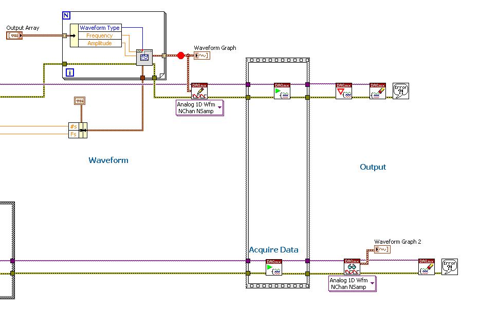
I'm trying to get my LabVIEW program to send analog output to a computer and read acceleration using the cDAQ-9184. Chassis output that I use is the NI 9263 and the chassis of entry is the NI 9234. I generate a signal of white noise using LabVIEW Express signal generator.
The first problem I have is the synchronization. I had an old VI that has begun to measure the acceleration just about a second after the entry has been given to the machine. I used the LabVIEW tutorial on how to sync the analog input and output, only to discover that it does not work with two different hunts. Then I found another tutorial that shows how to synchronize different frames between them.
The second problem is the cessation of the LabVIEW program. What I want to do is to generate the signal and then simultaneously send and read the input and output analog, respectively. It is because I don't want a phase difference or any shorter signal for a direct comparison. But as soon as the signal is sent to the machine, I want the entry to stop analog playback and then then the LabVIEW program must stop. I want to be able to choose any length of signal to be generated and stop as soon as the entire duration of the signal has been sent to the machine.
I tried 'DAQmx stop', "DAQmx Timer" and 'DAQmx's task made?' and none of them have worked for me. It is also my first time on a forum posting, so I hope I gave enough information. I enclose my VI as well. The VI shows I read an entry for the analog input voltage, but I am only using this to try to get to the work programme.
I'd appreciate any help I could get.
Thanks in advance
Peter
Hi Peter,.
I have some recommendations for you that I think you will get closer to your solution. First of all, I assumed you meant that you had 1 chassis (cDAQ-9184) who had two modules in it (NOR-9263 and NOR-9234). My next steps are based on this assumption, so if it's wrong, please let me know.
For your first question about the synchronization, the code you provided is very close to what you need. You need to do, however, implement architecture master/slave for startup tasks DAQmx functions. To do this, you can add another frame to the flat sequence structure and put the master start task (input voltage) after the start slave (output voltage) task.
To manage your second question and that the program ends at the point where you, the first step is to get rid of all the logic that you use with the local variable of length of time. Rather than use this logic, just wire the node "task performed?" of "is task performed?" operate to stop the loop. This will cause your loop to stop as soon as the signal is sent to the machine.
I have some other recommendations for you that will increase the performance of your program:
(1) rather than writing on file inside the last loop, you can use the DAQmx Configure Logging (PDM) .vi. You will place this VI between DAQmx Timing.vi and DAQmx Start Task.vi to the task of the analog input voltage.
(2) after the last while loop, you want to stop the task and analog outputs as well with another DAQmx stop Task.vi.
(3) rather than using a local variable for the entrance of displacement and wiring it in the DAQmx Write.vi, you can wire directly from the output waveform of the wave to build function node.
That should help you get started in the synchronization of these tasks.
-Alex C.
Technical sales engineer
National Instruments
-
Configuration of the basic Source of time to master for the 9234
I have several cDAQ modules I use to collect data. I use vi to Write can Express to save data to a file of PDM.
When you examine the recorded data files, the measured data from NI 9215 provide pleasant timestamps to match how the DAQmx task has been set up--delaying the sampling frequency of 1000 with a 1 ms in the While loop. However, although in the same vi - different tasks, but the same while loop - horodateurs of the NI 9234 do not correspond to the task of DAQmx implemented - sampling frequency of 1000 with a 1ms delay. After reading the material provided with the NI 9234, I found that maybe the machine clean master Timebase Source. There were documents that says he can be configured to be originally of Timebase of Master for the other modules:
Configuration of the basic Source of time of the master for the NI 9234 (Interface FPGA)
It is desirable to have the timestamps for data measured across all modules to match. We do not have the FPGA Module for LabVIEW. Is there a method in LabVIEW for all modules use the same master time base Source? I assumed that because all the data collection has place in the same while loop by using the time delay of 1 ms it was forced through the code. This hypothesis seems incorrect from my review of the PDM data files.
The NI 9204 provides a trigger only.
Software:
Windows 7
LabVIEW 2010 SP1
Material:
CDAQ-9174 chassis
Slot 1: NEITHER 9204
Slot 2: NEITHER 9215
Slot 3: NEITHER 9234
Slot 4; Vacuum
Hi MgDAQ,
An important concept to note is that the 9234 uses a delta-sigma converter and a clock of oversampling to read analog data. There is an inherent delay of entry due to analog and digital filtering built-in. Since the 9215 has a lower resolution there will be a lag the 9234 and 9215 finished. I've included some resources below:
What are the for the NI 9233, NI 9234, and NI 9237 valid sampling rates? : http://digital.ni.com/public.nsf/allkb/593CC07F76B1405A862570DE005F6836?OpenDocument
Synchronization of DSA, S and X series devices with a NEITHER-DAQmx single task series: http://digital.ni.com/public.nsf/websearch/78E44565FD87E7D686257108007F94F8?OpenDocument
Synchronization with NOR-DAQmx of acquiring dynamic signals (DSA) products:http://digital.ni.com/public.nsf/allkb/A133ED27DF9BCC5986256F2E004BA342?OpenDocument
Have you tried to put two modules in the same spot? Alternatively, you can export the sample clock 9234 and tasks installation separately.
Best,
CARISA
-
myDAQ inaccurate reading of the analog signal
Hello
I'm usign the myDAQ in lieu of a USB6341 who is busy on another configuration. The DIF is with the USB6341 I connect two analog inputs without any noise problems, whereas with the myDAQ, I get what you see in the image as an attachment.
Now, (the white line) of a flat line but often I get all these ouliers tips coming clearly through the myDAQ.
Two different voltage on two analog input signals of the my DAQ I can see the same spikes descending in the same moments for both signals, which is another confirmation that the noise is added by the myDAQ.
Also, try different myDAQs (we have many University) does not solve the problem.
Any idea on how to solve this problem?
Thank you very much.
Giacomo
Hello, Giacomo,.
Sorry for the late reply.
Now that you mention the myDAQ DMM.
Please note that the DMM uses a different circuit (Figure 2, page 5):
http://www.NI.com/PDF/manuals/373060e.PDFHow the signal looks like with the myDAQ scope Soft Front Panel?
Although the USB-6341 has different (and better) specifications seems to be rather a noise or signal problem floating.
Can you 100% certainly confirm that you do not see this problem with the USB-6341 when you perform a differential measure?Have you tried the method explained in Figure 7 on page 13?
Do you see a difference when doing this? -
Routing of analog triggers seizure through RTSI in MATLAB software
Hello
I want to trigger a framegrabber PCI-1424, when a certain threshold is reached to the analog input of my PCI-6259 DAQ card channel by using the corresponding toolboxes in MATLAB. Is it possible to get a software trigger located in the analog of the DAQ by RTSI card input, so that the framegrabber is triggered through the impetus of the RTSI? Unfortunately, when you use the following code.
% Create analog input, set software trigger and RTSI lineai=analoginput('nidaq','Dev1');
ch=addchannel(ai,0);
set(ai,'TriggerType','Software')
set(ai,'TriggerCondition','Rising')
set(ai,'TriggerconditionValue',1)
set(ai,'ExternalTriggerDriveLine','RTSI0')

% Create video object and set trigger to RTSI linevid=videoinput('ni', 'img0');
triggerconfig(vid, 'hardware', 'risingEdge', 'rtsi0')
the pulse of the RTSI is sent, when the analog input object is started with
start(ai)
, but the trigger for the software has no effect on the line of the RTSI. Help or workaround would be much apreciated.
See you soon,.
Hanno
I solved the problem via using hardware triggers:
...set(ai,'TriggerType', 'HWAnalogChannel')
set(ai,'TriggerCondition', 'AboveHighValue')...
Yet, software triggers do not seem to be transmitted by the RTSI bus.
See you soon,.
Hanno
-
Analog triggering on PCIe-6251 using BNC-2120 on Mac Pro?
Hello all-
There, does anyone know how an analog trigger using a PCIe-6251 card connected to a box of BNC-2120 interface? I am running LabVIEW 8.6 on a Mac Pro OS 10.5.6 and my VI of analog data acquisition seems to work but hangs up waiting for a trigger. The trigger analog signal must be applied to the terminal APFI0 and the BNC-2120 contains no connector with this name. On the M-series cards, APFI0 corresponds to pin 20 on the map itself, but I was not to locate any information that shows how the pins of the connector BNC-2120 connect internally to different spring on its façade and BNC connectors. Sales people NOR recommended the BNC-2120 as the correct one to use with the PCIe-6251, interface box so I think that probably one of the many connectors on the front panel of the box is wired to pin 20. Am I wrong? I spent hours to connect signals to the box in the hope of getting a trigger, and nothing has worked yet. To make matters worse, reviewing the VI to trigger a data acquisition using a TTL signal connected to all of the PFI 0... 9 connectors on the BNC-2120 just causes of VI to give undefined error message ' specific 89136 route cannot be met because the hardware does not support it.» The specifications for the PCIe-6251 indicate that a digital trigger should be possible through the PFI connectors, so it's a puzzle. I have an interface BNC-2110 box in the case which turns out be a solution, nothing about it is named APFI0 either. Any suggestion would be of interest. Thank you.
-Ken1
Hi Ken,
Unfortunately, the BNC-2120 doesn't have a connection available on the APFI your M series line. The BNC-2110 has this connection available.
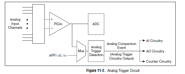
A possible workaround is that you can trigger off channels of analog inputs as well. Here is a screenshot of the M Series User Manual that shows the analog switch-off circuits:
There are a few caveats to trigger off AI channels (mentioned in Chapter 11 of the manual)
If you use a trigger to start, the analog channel that will be triggered off the coast of must be the first string in your scan list.
If you use an analog input as a reference or a relaxing break, it must be the only channel in the scan list.
I hope this helps!
Best regards
John
-
Registration of the analog inputs in continuous (Clipping)
Material:
(1) USB NI CDaq-9174 chassis
(2) NEITHER 9234 Analog Input Modules
(1) digital input module 9402 OR
Goal/Requirements:
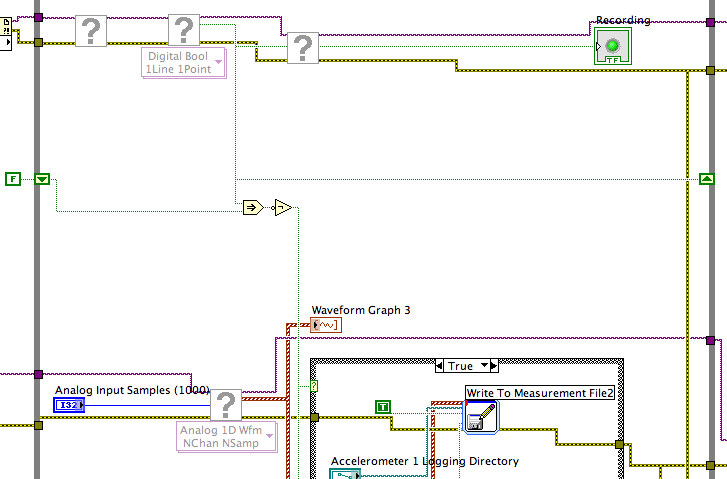
To read the analog inputs continuous only in digital input is "high".
Problem:
Timestamp in log file prooves that logging is not continuous. It seems that the first seconds of 0.6 of every second is recording, I guess the other 0.4 is used to write custom? I can't use VI SignalExpress for this application because logging must be triggered by a high digital input.
File is attached. Thank you all!
To detect changes in the digital input, you need to compare the current value to the previous. The easiest way to do this is to plug the output of digital playback on a shift register. The Boolean function involves will tell you when a transition has taken place. See the central part of the image below. If you exchange the true and the false case of case structures, you not the inversion function. Look at the help file for more information on what the function actually implies.
You must also change the wiring of the name of input for writing custom file FIle.vi so that the name is automaticlly changed. Depending on what you want the naming system to be, that it can be simple or rather complicated.
Lynn
-
Problem of generation of the analog output on PCI-7342
I use for the control of servo motor with encoder Axis 1 of my PCI-7342 feedback
and trying to out of the velocity of the encoder on the analog output of the axis-2 which is currently not used.
For testing purposes, I pulled out a constant 16383 (half of 32767) to the analog output
through load DAC.flx permanently, but there is no voltage on the map of the motion.
I read
http://digital.NI.com/public.nsf/WebSearch/102BE3EEED8A8B0DC1256EDA0059EC47?OpenDocument
and configure my 2 axis to be a stepper motor. I also tried to disable axis - 2. None of them works for me.
Also, I tried to read the value of CAD using reading DAC.flx right after that load DAC.flx is called.
Correctly, the value was shown on the screen. (See the attached figure)
I'm really bad now. Please, please, please help!
Any possible solution is fully appreciated!
Ron Liou
-
NEITHER 6052e: can I re - route the analog output of DAQ for PFI?
Hello
Does anyone know if it is possible to route analog output to one of the PFI (e.g. PFI0)? I use NEITHER 6052e and I would do the following: 1) output a signal to DAQ0; 2) then a few hundred milliseconds a signal of DAQ1; and then 3) read out a simple analog pulse on any output connector external to trigger an external device.
Thank you very much for your help!
Hello sometimes.
Could you please provide more information about your hardware configuration:
What devices are DAQ0 and DAQ1?
Are you using a PXI and PCI 6052?
When you say AO reroute to PFI do you mean you're trying to wire AO into a PFI line for release purposes or are you trying to exit and the analog signal of a PFI line?
-
read the analog signal 0-10 volts of NI6123
I'm reading the analog signal of NI 6123. The range of the analog signal is 0 to 10 volts. This works well when the signal voltage is 0 to 5v (0 ~ 32767). But when the signal is 5 to 10 volts, the value read is always 32767. I also tried the different reading function: DAQmxReadBinaryI32, DAQmxReadBinaryU16, DAQmxReadBinaryU32. The value is identical to DAQmxReadBinaryI16. My OS is windows vista. Here's the part of my codes.
**************************************************************************************************************************************************************************
Create analog data tasks.
DAQmxErrChk (DAQmxCreateTask("",&datHandler));
DAQmxErrChk (DAQmxCreateAIVoltageChan(datHandler,"Dev1/ai0:7","",DAQmx_Val_Cfg_Default,-10,10,DAQmx_Val_Volts,NULL));)
DAQmxErrChk (DAQmxCfgSampClkTiming(datHandler,"",RATE,DAQmx_Val_Rising,DAQmx_Val_ContSamps,RATE*MAXLAS));
DAQmxErrChk (GetTerminalNameWithDevPrefix(datHandler,"ai/SampleClock",trigName));
Create counter tasks.
DAQmxErrChk (DAQmxCreateTask("",&ctrHandler));
DAQmxErrChk (DAQmxCreateCICountEdgesChan(ctrHandler,"Dev1/ctr1","",DAQmx_Val_Rising,0,DAQmx_Val_ExtControlled));
DAQmxErrChk (DAQmxCfgSampClkTiming(ctrHandler,trigName,RATE,DAQmx_Val_Rising,DAQmx_Val_ContSamps,RATE));
DAQmxErrChk (DAQmxRegisterEveryNSamplesEvent (datHandler, DAQmx_Val_Acquired_Into_Buffer, SPLEEN, 0, EveryNCallback, NULL));
DAQmxErrChk (DAQmxRegisterDoneEvent(datHandler,0,DoneCallback,));
Start the task.
DAQmxErrChk (DAQmxStartTask (ctrHandler));
DAQmxErrChk (DAQmxStartTask (datHandler));
In the call back function:
DAQmxErrChk (DAQmxReadBinaryI16 (datHandler, SPLEEN, 3.0, DAQmx_Val_GroupByChannel, data.laser, MISS * MAXLAS, & (data.dataRead), NULL));
DAQmxErrChk (DAQmxReadCounterU32 (ctrHandler, SPLEEN, 3.0, data.counter, SPLEEN, & (data.ctrRead), NULL));
write data to the file.
data.cfile.Write (data.counter, sizeof (int32) * RATE);
data.cfile.Write (data.laser, sizeof (int16) * RATE * MAXLAS);
**************************************************************************************************************************************************************************
Thanks in advance
To make sure that your device is working properly, I recommend first to test the entry in measurement and Automation Explorer (MAX) analog. You can test your device by right clicking on it in the configuration tree and selecting test panels. See if you acquired signal 0 - 10V as you expect. The next step would be to try one of the sample programs that perform a task of analog input. These examples can be found in the start menu > programs > National Instruments > NOR-DAQ > text based code supported. Try an example that does an analog input continues and double bed (instead of binary data not adjusted).
Your program looks good at first so I found nothing that stood out. However, one thing to check is if your function generator (or signal source) expects a 50 ohm or high impedance. This could cause reflections of the signal and cause the device to possibly read a voltage of half of the desired value.
-
Hello
I searched many hours today in the internet and your forums, but it seems that this problem is not solved yet:
No writable calendars are configured for the invitations with the provider for Google Calendar.
My Thunderbird is 38.3.0 and the provider for Google Calendar 1.0.4.
I put calendar.google.enableEmailInvitations; true but it did not help. I also tried [email protected]... @googlemail.com. Calendar works fine, it syncs, I see all the entries etc. But I can't accept invitations even IF she must have write access.
What can I do? Is there a solution for this?
Thank you!
DanielUse CalDAV here to access Google Calendar via lightning. I have no experience with the add-on of the provider.
In any case, it is my understanding that you must assign an e-mail address to a calendar in order to be able to accept the invitations for this calendar. I see that in your screenshot.
You can try to remove the Google calendar in lightning and re-create it. Given that all the data is on the server nothing will get lost.
Or you may want to try CalDAV.
https://blog.Mozilla.org/calendar/2013/09/Google-is-changing-the-location-URL-of-their-CalDAV-calendars/
Maybe you are looking for
-
Satellite NB10T - A is blocked during installation of Windows 10 every time!
Can someone help me? I tried upgrading my laptop 4 times using windows update and every time it gets stuck. Every time the installation hangs at 83% complete across and 35% complete on the third phase, which if I remember correctly is something like
-
Issue of Apple Mail - account does not exist
There is no account in Mail, but the mail keeps asking for the password. What is happening on my new Macbook 12 "who migrated via Time Machine of my very old MacBook Pro. If the account in question does not exist, how can I find and get rid of it? Th
-
Bay of cluster fails to initialize constantly
I have a program where I have a table of cluster that enters a while loop like a shift register, and then is then indexed in a loop for to act on each item individually. To do this, the Bay of cluster must be initialized before the while loop, other
-
Hello world I have a Z820 HP Xeon Workstation, product # LJ452AV... As a first step, it would not start and press the power button would cause the power LED flashing red twice, to pause, flashing red twice, pause, etc. etc. According to the guide ser
-
HP Pavilion DV6-6031eo - black screen (backlight problem)
I ve bought a new laptop Pavilion DV6-6031eo 2 weeks ago, and it worked fine until today. The question: When I turn on the laptop, it starts as usual and the system works perfectly, but the screen is black, so I can´t use it, unless you use another m