connect multiple signals card NI USB-6341
Hallo,
I'm trying to connect the signals of several NI USB-6341 map.
This map has 16 channels but not 32 pins available.
for example if I want to connect a signal on channel 0 I connect to pins 1 and 2 and for channel 8, I have to connect to channels 2 and 3.
If I connect only channels 0-7, it works but if I connect channel 8 I do not get the real value of this signal.
any ideas?
Thank you
Theodore
Theodore,
This sounds like it should work. Basically, you use AI0-3 and AI8 - 11 for your four differential signals. This leaves you AI4 - 7 and AI12-15 free for single operation is complete. The configuration of the terminal can be defined on each channel. To do this, you can use DAQmx create channel several times to add channels with a different configuration to your task. If you need details on it, let me know what environment you'll be programming, and I'll see if I can provide more specific assistance.
Hope that helps,
Dan
Tags: NI Hardware
Similar Questions
-
Amnesty International and counter sync + USB signal stream (USB-6210 vs USB-6341)
Hi all
I'm at a stage of identification of a material suitable for the following tasks:
- 5 analog inputs (AIs) of reading at the same time, tensions at a rate of kSps (at least) 10,
- application captures 2 inputs using timers (detection of contours with timestamps), square wave entry with duty ratio of 50 percent and about 1.5 kHz frequency and variable pulse width / frequency (from 2 sensors hall, representative of the DC motor rotation speed and direction, quadrature signals), resolution of timestamps should be (at least) 50 ns,
- AIs and counters should behave in a deterministic way, and must be synchronized in a way,
- data to be transferred via the USB port of a host computer with Matlab Data Acquisition Toolbox (unfortunately not LabVIEW).
I've identified the long USB-6210 USB-6341 and potential candidates of material to accomplish the above tasks, but after reviewing several documentation and the topics of the forum, I'm still a bit confused, if both are fully working and my approach described below is not working properly.
Counters: I intend to use the internal time base available 20 MHz as being the source of meter to get into account the resolution of timestamp 50 ns. External impulses hall are used as sample clock (about 1.5 kHz, see above). As the pulse width varies, the sample clock is not constant.
AIs: Using a 10 kHz internal clock signal derived from the time base of 20 MHz for timing and analog inputs (trigger) start-up and counters simultaneously material should translate into the required synchronization and deterministic behavior.
It work? Other recommendations?
Next is the USB data transfer: all HAVE 5 and 2 data entry of the meter must be correctly transferred to the host computer (the corresponding rates are shown above). USB-6210 is capable of 4 USB signal flow, device USB X range (6341) offers 8 of them. Unfortunately, I could not understand the exact meaning of the expression "signal flow" still. Do I need 1 flow of input signals (would be 7 for my application described) or 1 stream for all analog inputs and 1 for counter inputs (lead 2 streams for my request). Is there no further details on this approach (more than Streaming of signals of NOR) USB signal flow?
Any challenge to the described application that I might have forgotten? 6210 USB seems to a very limited number of entry PFI, maybe even too low for my meter participate application?
Looking forward to your comments and advice.
Concerning
jAwA
1. I recommend the X-6341 series on the M-series 6210 sake of counters/timers. It is more of them, and each of them is more capable. It can also have a great FIFO embarked for meters that may be important in certain tasks, although I don't think that you currently deal with one of them.
2. your general concepts on timing & sync are satisfactory. You will be able to share and to route signals that help ensure synchronization and determinism between the timestamps for your various tasks. Note that for meter entry tasks, you need set up the trigger 'Arm Start' rather than the regular start trigger.
3 is not authoritarian, but I believe that the flow of signal # will correspond to the tasks #. For you, it would be 1 task of HAVE and tasks CI 1 or 2. (Not clear if you have 1 Encoder with 2-channel quad that would require 1 task of CI, or if you have 2 encoders with 4-way quad).
4. pay attention to the hall effect signals that are not virgins. Digital filtering is available and probably better on the X-series, the series M.
5. strictly speaking, edge detection is a type of digital input task that produces samples but no timestamps. Ideally, I would like to parallel wires on the two digital inputs for the entries of detection and counter change to position quadrature decoding. Then I would sample the counters Encoder 1 or 2 using the internal pulse 'event of detection of change '. I would create another counter timestamp change detects pulses as well.
-Kevin P
-
Computer does not start when connected to USB-6341
Hello
When my board 6341-USB is connected to my computer and the device is on, if I start the computer the USB-6341 module, the computer crashes before windows starts.
I said that the computer is an HP with Windows 7 64 bit computer. All Boot on USB configuration are disabled.
Is it possible to start the USB-6341 before the computer or not?
Best regards
CFOE
Hello
Unfortunately with my HP computer, because the HP hardware, the computer cannot be started if USB-6341 is connected and powered.
Best regards
CFOE
-
It is supported to connect multiple monitors using USB as a video source?
Original title:
USB touch screens
It is supported to connect multiple monitors (specifically wireless) using USB as a video source? If so, a hub would be able to handle this or the USB connection should be made directly to the motherboard or the PCIe interface. Thank you!!!
Hello
Thanks for posting your query in Microsoft Community Forum.
You can buy a switch HDMI that allows you to connect several devices to sources HD (e.g., monitors, TVs etc.) to your computer, while using only one cable HDMI (VGA or DVI) of your computer to connect to the second monitor. So you can get a HDMI switch on your favorite search engine for compatibility information for the switch with Windows 8.1.
If you want to project, or sharing of the wireless display, you can use the utility Miracast.
See also the article below to better understand.
Plug a second monitor or projector
Hope this information is useful. Please feel free to answer in the case where you are facing in the future other problems with Windows.
Thank you.
-
Hello
I m working on acquiring data usb 6341 and facing a problem. When I use two frequency counter in the same program, it fails to calculate the frequency (frequency meter task crashes). but when I use only one frequency counter works properly.how can solve my problem...?
-
Measure the time of the rising edges of a digital stream using a USB-6341
I have a DAQ USB-6341 map.
I use Measurement Studio (writing code in c#) on a Windows 7 computer.
I'm relatively new to the DAQ cards, programming, so I could ask something that is obvious (sorry if this is the case).
I went out a stream of digital pulses to an analog output channel. I wired this channel to one input of the meter channel. I am able to measure the number of edges upward to the inlet of the meter channel (since the digial flow is continuous, the number of rising edges increases with time).
I would like a time stamp of each rising transition and I like to keep these timestamps in a table without ever growing (or maybe bin these timestamps in a histogram).
Set up the meter channel to provide the timestamp data? (rather than just count)
Thank you for your help.
WRB,
The meter must be able to measure the relative time between the different edges of your signal. To do this, you will take care to set the meter to measure time. It will measure how long a full period of your signal takes. You can configure edge that you want to start with. You'll want to set up your timed 'implied' measure. This sets up the meter to automatically take action whenever a period is over. While it's not exactly a timestamp, you can find the distance between two edges by adding the time periods between the banks in question.
I see another technique that you can use. This would put the counter to edges of County one of the basics of time of your device (it has 100 KHz, 20 MHz and 100 MHz bases long). Then configure the task to use your signal as a sample (configuration to use rising edge) clock. Whenever the song occurs, you will get the number of ticks ticks selected timebase that took place at that time. One thing to note here, however, is that the counters are 32-bit wide, so your code will have to manage the overthrow of this charge if you are using a fast time and base running for long periods of time.
Hope that helps,
Dan
-
HP dx7500 microtour format: multiple video cards
I need more then 2 monitors and I think to install 2-3 video card on supprt additional monitors.
Is this possible with this model? s/n mxl9340qzl
I saw the specifications of your computer. He has only two PCI Express X 16 slots for video cards. one is available. There are three ways that you can go: 1) buy another video card to fill the vacant unit 2) buy a USB video adapter or 3) buy a nVidia Quadro or another workstation that supports multiple video cards.
You should make sure that the power supply unit (PSU) has enough power to run two or more cards.
Please click on the button + Thumbs up if I helped you and click on accept as Solution If your problem is resolved.
-
Send the signal current/voltage/USB DB25 to regulation of pump to
Hi all!
I want to control the speed of a pump with LabVIEW (Thermo Fischer FH100M, Manual) and so I have to send a current or a voltage signal to the pump. The pump has only one DB25 port. As my laptop is not a port DB25, I tried to control it with a USB converter.
I had only a converter USB to DB9, so I started with (laptop) USB-DB9-DB25 (pump) > >.
When I connect the pump on the USB port, it is instantly put in market, but in a strange way.
Is it possible to use this configuration? Or is it possible to use at least USB-> DB25 (I have the Setup, see manual page 45/3-19)? Then, I would order that the cable companies.
Or do you have other suggestions?
Thank you very much in advance!
Tobi
Tobi,
Stop it! Do not connect your converter to this device.
When you say "Converter USB to DB9" are you referring to a USB converter to RS - 232? DB9 is just a connector and therefore DB25. TOU can wire anything to this connector. Your converter is probably wired as a serial RS-232 port.
The manual shows clearly on page 3-19 and the following pages that the control of the pump is NOT wired for RS - 232! By looking at the speicifications for the inputs and outputs you shown on page 3-20 and 21 may damage the USB to RS-232 conveter or the controller of the pump by connecting them.
To control this device you will need to a DAQ with analog input, analog output, material inputs digital, digital, outputs a counter. You will also need some external circuits such as transistors or relay static solod DC in proportion.
Lynn
-
Model generation with USB-6341?
Hi all
We have developed a software quasi multifunction 'device-independent '. This sw is capable of generating the sequence shot timed with the device really used. Up to now, we have used devices PCI-6025 and USB-6221, but now we bought a USB-6341 and when I try to use a message of 200565 error pops up: "specified digital channel contains more bits supported by the version 8 bits of the Port DAQmxBase write.» Use the version of DAQmxBase Port write who takes in charge the broader digital ports. Minimum size of write in bits: 32 "
I tried to change PORT0, PORT1 and PORT2 but only PORT0 is legal for the model generation process and it requires DAQmxWriteDigitalU32 function...
I don't understand why.a / 6341 contains 24 DIO lines
b / only 8 DIO lines are clocked by materialThen there are 24 DIO lines (i.e. 24-bit 32 no!), but only 8 lines are timed by the hardware and I want to use only this 8 lines for model generation!
Our whole software is based on 8-bit pattern-berries (writeArray type is "uInt8"). If we cannot use this structure, we must rewrite dozens of functions...So, how can we use the function of DAQmxWriteDigitalU8 with USB-6341 or what can we do?
Thank you
-George Cs.-
Dear George,
It is an interesting question, which may seem a bit unintuitive at first. The main reason for the 32-bit write operation (although the USB-6341 has only 24 DIOs) is that the functions and the driver support other devices too. As you can see in the manual of the unit (http://www.ni.com/pdf/manuals/370784d.pdf) X Renault series supports digital IOs up to 32 bidirectional signals.
To keep things consistent exploitation of 32 bits is required even if you use only a subset of the available ports.
I hope that this helps to explain.
Best regards
-
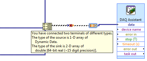
How to use generate multiple signals on a single DAQ Assistant
I am trying to generate several AO on my DAQ card, but I kept getting an error. I looked at the error and he said that I had to use a single DAQ Assistant. So, I created one, but I can't understand how to connect the signals. I get lines that don't connect. Is attached a picture of the installation. Thank you!!!
If you want to use the type of dynamic data, you must use the appropriate function. Do not use the construction. Use the Signal to merge. Then wire you the output of said directly to the Assistant.
-
Help on unit Photos and videos not Visible when connected to the PC via USB. I also tried to restart and reinsert the SD card but no response what happens each time I take pictures and try to transfer to the pc via USB please help to recover the photos suggest something?
ampawase wrote:
Help on unit Photos and videos not Visible when connected to the PC via USB. I also tried to restart and reinsert the SD card but no response what happens each time I take pictures and try to transfer to the pc via USB please help to recover the photos suggest something?"A wireless connection with the mixture, use the file manager, hold Media Card - Photos - 'Shift' or ' Ctrl ' key - select thumbnails - right-click - Save slot - selecting a folder on the pc and save them.
-
Connection of signals ContactPicker
Hello
I can not connect the signal to a ContactPicker. Here is my code:
ContactPicker *contactPicker = new ContactPicker(); contactPicker->setMode(ContactSelectionMode::Multiple); bool success = QObject::connect(contactPicker, SIGNAL(contactsSelected(QList&)), this, SLOT(onContactsSelected(QList &))); if (success) { // Signal was successfully connected. contactPicker->open(); } else { // Failed to connect to signal. alert(tr("Didn't connect the picker signal")); } I had similar problems when connecting the signal of a SystemPrompt, but I solved it by adding all the dependencies (in silence) in the hard drive file: I found an example of work and I saw everything what needs to be included. But for the ContactPicker, I can't find an example of work. Any help? Very much appreciated.
Thank you.
Hello
const and & can be omitted, but they are not equal to a non-const reference.
The following should work:
Definition of slot:
void onContactsSelected(const QList
&contactIds); Connection:
QObject::connect(picker, SIGNAL(contactsSelected(QList
)), this, SLOT(onContactsSelected(QList ))); -
How to register for an event when the device is connected to the PC in USB mode or sync
I develop application on blackberry with phonegap.
I want to hear event when the BlackBerry device is connected to the PC by USB MODE or sync.
I saw mediagallery and applications Filemanager showing the dialogue that the application cannot be used when connected to the PC in USB mode.
I want to display dialog similar to my request.
Can anyone please help on how to do it.I saw blackberry webworks API
public static Boolean blackberry.system.isMassStorageActive)
who says if massstorage is active or not.
But I can't keep on request this API every time. I'm looking for an API that gives me the reminder.
Can you please help.
On the side of Java, this can be done by implementing a FileSystemListener and the rootChanged method:
public void rootChanged(final int state, String rootName) {
    if (rootName.equalsIgnoreCase("sdcard/")) {
        if (state == FileSystemListener.ROOT_ADDED) {
            /* SD Card is available. */
        } else if (state == FileSystemListener.ROOT_REMOVED) {
            /* SD Card is not available. */
        }
    }
}
I was not able to find a corresponding WebWorks API or API community well, so I think you need to create your own custom extension to implement this feature of the listener.
https://developer.BlackBerry.com/HTML5/documentation/using_javascript_extensions_1866976_11.html -
How to configure a VM with multiple network cards to see Agent?
How to configure a VM with multiple network cards to see Agent?
We can archive this requirement by configuring the subnet used view Agent.
The subnet determines which view address of Network Agent provides the server instance to connect to view for the client protocol connections. The view on VM officer has more than one NIC
Follow the procedure below:
on a display Agent installed VM,
* Recording of VM session.
* RUN--> type regedit or type regedit.exe at the command prompt
* Create a registry entry to configure the subnet.
For example: is HKLM\Software\VMware, Inc. \VMware VDM\Node Manager\subnet = n.n.n.n/m type - REG_SZ.
In this example, n.n.n.n is the TCP/IP subnet, and m is the number of bits in the subnet mask.
-
I have an imac 27 "... on power there is no signal to startap, usb ports are not working and its deadlock with the logo of the Apple with the circle of rotation... Help, please
Wake the computer to your Apple store or Apple authorized service for the service provider. He probably suffered a hardware failure.
Maybe you are looking for
-
Adapter Toshiba 2 weeks out of warranty
I've been very disappointing to know that Toshiba will honor no guarantee of the a/c adapter as its 2 weeks out of warranty. What happened to the good will and good gestures. I used to work for after-sales service and we would always honor guarantee
-
XP Pro constantly fails to 'install' MS Office updates
Download updates, but the installation is a constant loop of = FAIL. Any easy repair for a non - IT, home user?
-
LaserJet M525 - AddressBook General error Services
Hello I have several M525s in my fleet, which all report the same error message in the event log: "Address book general services error. After the last round of updates fimrware to 20140529 this error started logging and fill my Pages to the event log
-
I get this message: mp4filelibu.dll is missing.
Original title: mp4filelibu.dll I use a Canon sfot to my camara A470 and I get this message: mp4filelibu.dll is missing. I understand that might be avirus, how have Karpesky escaped? How can I solve this problem? Thank you
-
Visual studio displays an error message indicating that these functions are not in the context.
Original title: c# I am using visual studio 2010... but when I use commands like ToInt, den ToDouble etc, it shows an error indicating that these functions are not in the frame... Please give a solution... Thank you