Control of Stepper Motor with case NI USB-6009
Hi all
I am currently creating a movement control system with a double movement actuator
and two bipolar chopper drives (see table), which should power the motor. We already have a NI USB 6009 in our lab, so I was wondering if I could use it to send signals to the two pilots to control the speed and direction of each axis on the engine?
Enclosed driver's manual indicates that input signals should be 0-5 V DC (TTL logic). I have been informed by the engine distributor that the 0-5 V DC TTL drivers required, the signals are analog. The NI USB-6009 manual reading, there are two 0-5 V analog outputs on the acquisition of data usb so I could provide two signals?
There are often posted however similar problems, it is usually a digital signal NI6009/6009 sends the driver. Looking at the driver's manual, can someone tell if an analogue signals or required as I have said, I was misinformed or 0-5 v DC signal will be enough. I can get more in touch with the dealer if you have any questions you guys think I should ask him.
Thanks in advance for any help! It is much appreciated.
I looked in the manual and it doesn't seem to be very clear. I know that the USB-6009 case is capable of AO and DO, then you would be although it is. I could contact the Haydon Kerk support for more concrete details on the gap between what says the manual and what they told you.
Tags: NI Hardware
Similar Questions
-
Implementation of multiple digital outputs with a box USB-6009
Hi all
I write the code to implement a USB-6009 multiple digital channels, digital outputs independent. I have configured the function of "DAQmx create Channel" to create 'a channel for each line', but I can't understand how to access and control these channels separately. Pointers would be greatly appreciated.
Thank you!
I thought about it. Never mind.
-
interaction with chip via usb-6009
I know that the title is somewhat ambiguous. My problem is the following:
I am using an optical mouse as a tool to measure position. I use a chip ADNS-2083 (did not have much luck to find the datasheet, someone else got the chip before you check around the news available.) and I'm following an instruction manual on how to make this project very, only that it uses Arduino and LEGO NXT instead of Labview. I have at my disposal a USB-6009 device, which is connected to the + 5V and GND, SDIO, SCK pins on the controller chip. For the record, I'm using Labview 2009.
Now, the mouse is powered and as such, the LED light up or what - not. However, I don't know how to pass information to the chip via SCK and SDIO. My programming experience is limited, and I never have this type of electronic products.
What I want to know is how to pass 7-bit addresses to SCK and SDIO for control both, and what are the best ways to accomplish this through Labview.
Thanks in advance a ton.
PS: I have attached the pdf file of the manual mentioned above.
cosmicomics,
A quick look at the tutorial that you talk it seems that ICR optical sensor mice using I2C. You will not be able to use the 6009 to I2C communication, instead, you can use the USB-8451, designed precisely for this purpose.
Please let us know if you have any other questions.
Kind regards
Sam K
Technical sales engineer
National Instruments
-
With the NI USB-6009 analog input lag
Hello
I try to acquire analog signals with NI USB 6009 using LabVIEW. (The signal is 50 Hz of the functional generator).
However, the acquired singnal has dynamic splitters, which is NOT observed by my oscilloscope.
I have no idea why this phase shift occurs.
Any information is welcome. Thank you for reading.
An image file will not help. Post your real VI. If Firefox does not work, use explore or Chrome to fix your VI (s)!
You have here a Subvi, I don't see what's inside and how it is configured. In addition, this while loop is ridiculous: there is no button to stop him running. Never use the red button to abandon for a normal shutdown of a VI!
Why you have configured NChan NSample? Measure a unique signal, Yes? For example, use 1 channel only.
Edit: why do not you play first with an example given, delivered with LabVIEW?
Your LabVIEW, go to the Help menu--> find--> material and output examples--> DAQmx--> entry--> and open 'Input.VI - constant tension!
This VI allows to enjoy your analog signal.
-
Hello. I have a problem with a prototype of movement control, and I am at a loss to know where to look next.
I run a computer running Windows XP with LabVIEW 8.6.1. The computer contains an NI PCI-7332 motion controller nine connected to a card NI UMI-7772 control a P70360 stepper drive. I'm trying to run a command of CTP 11 ELF 11 Danaher engine with little success.
All the lights on the boards are the appropriate color. I followed the implementation of the steps in "Getting started: P7000 series Stepper Drives. I have the correct indicators in the interface of MAX, and I can not even the motor to hum a little when I press 'Start', but the axle does not turn. I check the wiring of the driver of the engine and both Multimeters and diagram agree that, at worst, to run it back. This is before any programming LabVIEW. I'm just trying to make the engine start with MAX.
Any help would be greatly appreciated as this is my first time setting such a system.
Ben
Hi Ben,
Looks like your engine, and if your player are not compatible. 11 ELF 11 CTP is supported by the P70530 and not by the P70360 (see table 5 in the P7000 manual start-up). The P70360 (320 V) bus voltage is too high for this type of engine. Please contact your local branch OR for redemption for the right hardware options (you will need to swap the drive or motor).
In addition, I highly recommend using the software tools P7000 in combination with a cable (P/N 780099-01) series to set up the reader. It gives much more flexibility to use switches dip and you can optimize the performance of the drive and motor by adjusting the inductance of the individual motor drive.
Kind regards
Jochen Klier
National Instruments
-
A motor with encoder closed loop. Can I connect an other encoder without using an engine?
Thanks to LabVIEW with a PCI-7332 and an UMI7774 interface to control a stepper motor with encoder feedback. System is configured in closed loop for the control mode. You will need to add a different encoder to the system without attaching a motor. I'm validation of encoders to each other. Is this possible? Should what kind of latency I expect? I have attached a simple vi. Need to buy one before the answer.
Thank you
You can just plug the second encoder to the second slot without an engine it. Then you can use reading encoder Position.flx to read its position or do whatever you want with it. What about latency times, how are you trying to go under?
-
motor current by using NI USB-6009
Is there a way to measure current of a motor with the NI USB-6009 case? I understand that I must use I = V/R. But it seems that with this concept, I would have losses for the engine, so I used a small resistance and measure the voltage across it. I'm trying to get a reading of the Spike current with a voltage to an engine No. Thanks for the help.
-Nick
The shunt would be just to go online with the engine and measure the voltage drop across the resistance.
Eric
-
Where can I find the tutorial or sample Vi to control the position and speed of the stepper motor?
Hi all
I use a driver on 3rd for a stepper motor and I use USB6356 as the controller to drive the motor. Could you recommend some VI sample or tutorial on the position and the speed control of stepper motor?
Thank you
The best
I think that what you are looking for is the LabVIEW SoftMotion Module:
http://sine.NI.com/NIPs/CDs/view/p/lang/en/NID/14234
Here is a good resource on stepper motor theory:
http://www.haydonkerk.com/resources/StepperMotorTheory/tabid/192/default.aspx
My recommendation would be to start from a counterexample of LabVIEW. These can be found in LabVIEW > help > examples > material input and output > DAQmx > input meter, output meter.
-
Stepper motor and LabVIEW - loop
Hi guys,.
I'm trying to control a motor step by step using a 6008 OR. I did a little research and I know that there are some problems using the 6008 with a stepper motor, but for my project, it should work perfectly.
What I need:
A VI that will control a stepper motor and rotate the engine until the angle typed. The engine has a 7.5-degree increase. I build a VI that will continue to run the engine at the desired angle whenever I press the button 'GO '. But it only works for the first time that I press 'GO '.
The problem:
After the first iteration, if I press "GO" once again, it does not apply tension on the next pin, because it restarts the loop. And that makes the engine to become crazy.
The solution: (I don't know how to implement)
Make the engine go back to the initial position when I press the button "RESET". In the case, whenever I want to change the angle, I just push 'Reset' and then 'GO' and the engine would go to the desired position. Or even better: when I press the 'GO' button, the engine would automatically return to its initial position and then move to the desired position.
BTW: I would like to return to the initial position without having to do a 360 loop. I know how to do this.
The VI that I created is attached to this message.
Help, please.
Thank you.
Hi, Gear,
I tried to drive the stepper motor by a table of pre-defined and rotation of each step.
Hope that helps.
-
Driving a relay 24V with a USB-6009
Hello
Someone at - it a circuit diagram of how to drive a relay 24VDC with a box USB-6009 and a ULN2803? I've done it before, but I can't find my old tickets and for some reason that I can't get it going now.
I put the chain properly by using the DAQmxBase utility, but I still can't relay to pass.
Any help much appreciated.
Thank you
Got sorted! It was my software not the hardware.
Thanks for the tips anyway.
-
OR USB-6009 and Tek TDS2024C comparesment
My apologies if this topic was already discussed, but I searched through the forum and manuals and can't find anything.
I have a problem with measurements in parallel with TDS2024C NI USB-6009 and Tek.
I measured the noise high frequency on 10 s window.
I used the data logger with a frequency of 40 kHz connection in parallel with TDS2024C (which reached 250 Hz on 10s window) and got very different results.
On the attachment figure, first signal comes from screenshot of scope data and the second of the NI USB-6009 islogged.
Can someone explain to me why are these so different results?
Different sampling frequencies could easily explain it. Try to run the USB-6009 case at the same rate as the scope and see what you get. I also think that the TDS2024C has fewer bits in the ADC, which could also cause differences.
-
Recommend components for the plant of thumbnails that will be automated using NI USB-6009
I build a treatment for a University project and I'm looking for a few recommendations of components that work well with the NI USB-6009 case. Because of what is a project of the University, my budget is $ 100 and I need the following:
a float switch or something similar
a solenoid valve two-way or three-way
a pump
a pH sensor
a temperature sensor
a camera
I understand that I may not have a sufficient budget for all these components, but all product recommendations would be appreciated.
Hello
I recommend using the following tool to see examples of projects other users worked on in order to determine the appropriate components: http://www.ni.com/examples/
I hope this helps!
-
Why LabVIEW 2012 does not support USB-6009?
Hi all
I recently installed LabVIEW 2012 and DAQmx 9.6 (and also tried with latest version) in my PC with Windows 7. I have the version of Explorer 5.4 measure and automation. I'm working with hardware DAQ USB 6009. Everything seems compatible, but when I try to post data acquisition, it fails. However, I used to use this device (since I bought it last year) with the other PC that has the Windows XP operating system and the older version of LabVIEW 8.5.
What can I do with LabVIEW 2012 is a message "a 88302 error has occurred." and "This could be an internal error."
If someone has an idea to solve the problem, please let me know.
devkotaj
Hi devkotaj,
The USB-6009 device should work perfectly on Windows 7 with the software you have listed. This looks like a problem of configuraiton of material for me.
What are you trying to do when you receive the error 88302? This error usually indicates a corrupt DAQmx driver, which may result from the installation of several DAQmx versions on the same machine. Have you tried repairing your installation DAQmx? I could uninstall DAQmx from the Control Panel before installing the latest driver. You can see our procedure to reinstall or uninstall recommenedd here.
I hope this helps!
Andy C.
Engineering applications
National Instruments
-
USB-6009 slow output signals using SignalExpress - error 200077
We have a Council of USB-6009 and Signal Express version 3.5.0
We want to generate low-frequency, analog and digital outputs to simulate some slow movement process.
We have created the signals and their generated as output, put when we RUN the project, we get error 200077, which seems to indicate that we must use On Demand distribution of signals.
If we choose On Demand, then the generate DAQmx says we have a missing entry.
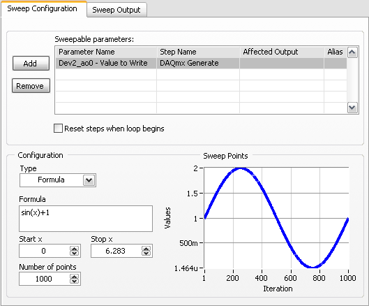
So, what method should be used with the slow USB-6009 to generate box (.01Hz and slower) analog and digital outputs?
These are 2 of the projects, we tried - using On Demand, N samples, continuous, internal, and external triggering etc..
Thanks adavance for your help...
Welcome to the forums of Steve,
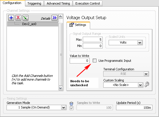
I have good news for you. I played a bit with the sweep and actually got a code facing up to generate a slow signal. I went and tested it with the 6009 and he was able to run without any errors. I joined here, but if you have to open (or anyone else in the future), here are some screenshots of how it works. If this works, feel free to make the forum as resolved while others can locate a solution a little easier in the future.
Scan Configuration:
DAQmx Config:
-
Ideas for driver control of motors stepper with USB-6009
I have a stepper motor driver that supports a digital input for the control signal. Each rising edge on the driver entry corresponds to the movement of a single step. I have two devices USB-6009. Is it possible to generate a digital signal with the 6009 faster than 150 Hz? I need produce variable frequency in the interval from 0 to 1 KHz.
zaphead,
The OID on your 6009 being timed sofware it comes out as fast as your computer all supports. If a computer faster or less current will help things but you will get not the 1 kHz you need. The best way to get this is to use another card that supports hardware timing DIO.
Maybe you are looking for
-
almento como a velozidade do mozilla firefox?
FICA carregando...
-
I was warned in advance that Yahoo toolbar would be incompatible but not that there is no toolbar at all, since Google does more than Firefox 5. I guess I'll have to go back to explore because I need not toolbars, no? Is there such a thing as a Firef
-
I have a hp deskjet d1520, I try even money on the ink, can I print using only the black cartridge
-
original title: error by e-mail I tried to send a copy of the invoice to our account and caused and error, now I can't out emial. Please tell us how to get rid of email error, warning burst to send and it error.
-
I'm using an EOS 7 d for 1080 p HD video shooting. New to SLR camera and digital video. I have watched several tutorials but do not yet have a good understanding of what the best practices for the development. If I put the camera in AI Servo it will