Control PLC Modicon-Quantam of Modbus TCP/IP Ethernet.
Has anyone use LabVIEW to program a PLC Modicon-Quantam successfully using Ethernet TCP/IP? I tried the examples MB Ethernet (master/slave) in the download nimodbus121 and it doesn't work. I really need to know the best way to connect and communicate to a PLC Modicon-Quantam using LabVIEW, Ethernet Modbus TCP/IP using the Excel spreadsheet. I need to write entry registers (write) shift in and read from holding registers. The software that I SMTX Modbus/TCP Master control ActiveX does not completely for me. I can ping to the controller from cmd prompt. I saw this webcast - creating a server of e/s Modbus TCP with the LabVIEW Datalogging and supervisory Control Module 8. I've also seen a webcast on OLE for process control (OPC). What should I write LabVIEW control and view records by using LabVIEW flags? Someone at - it a LabVIEW example that I can start with? Should I buy the DSP module for $1280,00? This will solve my problems?
If you have found return data that you do not understand that I recommend trying to send output known of the automaton at least to determine what kind of conversion has to happen. This document talks about the Optomux protocol that can be used with programmable automata. You will need to find specific documents that tells you how to convert these data into LabVIEW. You can also start a new forum, since this is a separate issue from the original.
-Hunter
Tags: NI Hardware
Similar Questions
-
You can trigger through communication Modbus TCP/IP PLC data acquisition without using a loop for?
Hello
I am trying to contact a facility through a Modbus TCP/IP communication PLC. I'm new to this method, but the idea is that the installation will send the logical (Boolean) values 1 bit by ethernet to my workstation which read and then will begin data acquisition. Basically, I need a triger to come to my pc. I placed my vi inside a structure case T/F which will run according to the signal, it receives data acquisition. However, for it constantly waiting, I put this in a loop for. The works of vi, but playback signals sometimes lagging behind due to the loop for. If I take the loop out and just run labview permanently, it works perfectly, but I know that the option is only for debugging and should not be used. So my question is, is there a better way to wait for an incoming signal?
Hello!
Please note that the order of execution of the write operations on the shared variable 000002 is not determined.
For example, nothing prevents this order of execution:
(1) value false 000002
(2) set to true 000002
(3) execution of the loop
In what concerns the delay, you might consider placing a waiting vi in the case of 'false', or the loop uses 100% of CPU if I'm not mistaken...
Kind regards
Marco
-
need to read siemens S7 i/o in labview via Modbus/TCP
Hi friends,
We are developing an industrial project and facing a scenario in network as follows...
Abt Project brief
Its a treatment to the sweage plant. We use the NOR-PAC and Labview version: 8.5.1 for process control. We got a few 3rd e/s Party which must be monitior in Labview.
Details of 3rd party
-Siemens S7 - 200 with EM 277
In our factory in the entire network is fo - TCP/IP. Now, we must take Siemens of e/s via TCP/IP in labview. To what extent this can be done. If it has to do with Modbus/Profibus converter can we do the configuration online without distrubing plant.
Thank you & best regards
Pravin Moussa
Systems engineer
Hi Pravin
I am not sure of your diagram exactly what is your network. You have shown a link of the FO-tcp-ip for the S7-200. How does this happen? Or did you ask here, to work on options?
Since the S7-200 can be slave profibus DP through the 277, it won't 'see' some other profibus IO anyway. You can use a Siemens CP243 module to give tcp - S7 - 200 ip connectivity. Also, is there a connection of profibus S7-300 and S7-200, all e/s of the S7-200 can be mapped to the S7-300, so you only need to worry about communicating with the S7-300.
Another option
Regarding modbus, they charge a lot of money for the Step7 from siemens modbus library. On the other hand, the S7-200 comes with a free modbus library, but it's the modbus RS485, not modbus tcp - ip series. Perhaps you could use this and use one of the many series-to-ethernet doors available.
-Michael
-
LabVIEW Modbus TCP with VFD. Could not establish connection / error 56? Any thoughts?
Hello
I'm trying to establish a connection to a VFD (Variable frequency drive) for academic research, for testing purposes. My implementation consists of:
---> LabVIEW (Master)
---> ABB ACS880 VFD (slave) with adapter from Fieldbus FENA-01
---> (ABB motor induction)
---> (Internal Combustion Engine)
First of all, I'm new to Modbus TCP protocol, but I went through all the white papers of NOR, I have read and followed all the instructions from the manual of the VFD and the fieldbus FENA-01 adapter manual. I'm also pretty new to LabVIEW, but I'm confident, I have the knowledge to create the necessary VI.
I created a simple VI who would be able to read some registers the VFD, which is attached below. The VFD is connected by Ethernet to network local ethernet and the Master PC is connected to the same network. When I run the VI, 56 error, which as I read from other messages of the forum is to not get answer within the given time.
I tried the things:
--> Check all cables are connected properly
--> Double check the manuals
--> Checking the FENA-01 in the chassis, which gives the indication of waiting for query modbus
--> Looking for a gateway IP address, but I did not find, so I expected, I don't have to add it to the VFD parameters
--> FENA-01 refreshing settings that always translates to "offline" status
-->, I also checked in Labview > tools > Options where you check TCP/IP and there no port 502 written but I do not change it cause I had to leave the laboratory at the time. The port number was something like 3363 (something like that again)
Issues related to the:
--> Do I need to specify a new device somewhere in LabVIEW or in the control panel?
--> What I need to create a separate VI to make the connection?
--> What 'send 1150 for operating loan' and ' send 1151 for operation "means the control word?
I would be very grateful if someone had information about this before the end of the week. I'm running tight on my period and I just can't stand this VFD with the limited power of the local command of monitoring mode.
Thanks in advance for any help.
Neo
Hello, the problem is solved, and this could be a solution to problems like these.
The IP address of the car was not on the same network as the Local Ethernet network connected to it. The IP address of the disk was 192.168.0.16 and the network was on 192.168.1.1. Once the IP address of the network changed to 192.168.0.1 communicated properly.
I also have ping after and showed the communication.
Thanks for the reply TST.
Peace,
Neo
-
change comm driver for koyo modbus tcp
I have a working system that uses a koyo plc and modbus driver. I change to the controller for a scadpak with modbus tcp. Is it possible to switch the comm driver without having to recreate all the tags and the screens that were created under the former comm driver? I know I have to change registers views use to reflect the scadapak controller, but I hope I don't have to start!
OK, I got it work. I created a new modbus ethernet driver. Then I exported an empty xls file to this new driver. I then exported a xls of the FORMER pilot with the old information. With the two spreadsheets open, I then cut and pasted the old news into the new xls file. Then, I changed the former membership numbers for the new numbers, which I used with the new PLC. It WORKED! I think it is best when you change the PLC.
-
Modbus tcp read holding registers return not requested quantity
Background: I have a client using ELAU motion system - they record data with records they want to be able to read on a cRIO match with some analog FPGA data (I have digital handshaking going on for this).
LabVIEW 2010 SP1
cRIO-9074
With the help of the library of VI of MOdbus.llb OR communicate with the other system. I can open the TCP communication without problem and actually get SOME records, but not ALL registry data, I want to read.
I want to do is read the registers individual operating 330 U16 values. I know how the data are split to represent different lengths (i.e. most of the data items use 2 records number represent a 32 bit). I want just to read all of the individual records and analyze the data in another VI to convert it to other data types.
I provided the .vi MB Ethernet Master Query (poly) with the starting address for the first register, then the amount of 330. The polymorphic instance selected is "reading record keeping. The array returned by this VI via 'Holding Registers' is only 74 elements and not requested 330. I have no exception code and no error in LV. Is there some intrinsic limit, i.e. the number of Holding Registers that can be read?
I do not use the (not sure if necessary) MBAP header entry.
Thank you.
Simple solution once I dug in the series MODBUS/TCP protocol protocol documentation out there via Google.
History of the modbus function series is the limitation that carried over TCP - the maximum amount of bytes in the pack a data can be only 256 bytes. So I was limited to approximately 125 ~ records at a time.
256 bytes is 2048 bits. The use of the 16-bit registers which gives maximum 128 registers. I went with 125 followed making easier totals.
-
Modbus tcp 1.2 problem with labview 8.5
I have a new upcoming project that involves a link to modbus tcp. I downloaded version 1.2 of the modbus library and installed. Everything appears on my palette, but if I try to open one of the examples he comes as for version 8.6. I am currently using 8.5 but the download says it works all the way back to 7.1. Any ideas?
Are you sure that you have selected the correct folder for the "installation"? When you download the 1.2 OR Modbus Library (here: http://zone.ni.com/devzone/cda/epd/p/id/4756), you get a zip file. Inside this file, you will see 4 folders, one for LabVIEW 7.1, (issue 71), one for LV 8.2 (case 82) and also records 85 and 86. So make sure that you have done the installation with the correct folder.
Let us know if this helps or not.
Kind regards.
Robst.
-
Hello everyone:
I am facing a strange problem on the modbus TCP/IP communication, we have built the connection and use the modbus library OR read the analog signals, it works, but the return signals seems odd, for example (A 40-0 for value: 5, 3F80 for value: 4000 to 1 and 2), I went throngh modbus specification documents , but in these values do not respect the rules, is there anyone has idea about this?
Thanks in advance.
Best regards
Are you waiting for floating point values? Modbus transfers bytes. It's the software front end to convert the bytes floating-point or of other signed/no signed integer values, 32-bit integers...
-
Modbus/TCP connection to the controller of power Eurotherm EPack
There are examples of how to connect to a power controller Eurotherm EPack a modbus/TCP connection?
I downloaded the Modbus LabVIEW ni_lib_modbus_library library - 1.1.3.32.vip and installed using VIPM.
However, I am not familiar with the Protocol modbus and terminology such as coils, keeping records.
I can't even properly run examples for Modbus master and slave to this library :-(
Most important for me now is just to read the value of the artwork process.
"ITools" Eurotherm controller software provides information about something I think are an address of memory the value of process I want to read.
However, I have no idea how to set the various parameters to get successfully connect and read the value of the process.
Trying to solve my problem, I managed to have basic communication and engineering data conversion.
Now I can read values of process as the power line frequency, voltage and others.
Once you know, it's very simple (once you have the modbus library)

Some things that remain unclear:
-What values are 32-bit and 16-bit?
-is the method of addressing identical for all parameters?
-is it the same for reading and writing?
I would like to be able to write the target value, for example.
I'll contact the seller for these outstanding issues. The manual is not really clear (at least not for me). He mentions that some values may be treated differenly (they 16bits, but globally, so 5001 with a scale factor of 100 means actually 50.01 for example).
See the attachment for reading cover base.
-
How to connect Labview to PLC Modicon Quantum (140 CPU 311 10) with Modbus
I was wondering if someone could give some tips on how to connect Labview to Modicon Quantum plc (the card is 140 CPU 10 311). I am eager to serve a Labview HMI to control the controller that is used to implement the control PID with a VFD. Currently I can communicate via Modbus to the API for programming using UnityPro XL, but I have no idea how to connect Labview. I read the article on place OR "connect Labview to any PLC via Modbus", but I don't know yet. Any help will be greatly appreciated.
Hey Greener.
Communicate with the PLC via Modbus usually requires the Datalogging and Supervisory Control (DSC) Module to have this feature available in LabVIEW. The white paper which indicated you using this module, which may explain why you can't get the communication at work. If this is something you don't have, and purchasing a license is not an option, then you might be able to use Modbus unofficial libraries to get the functionality you need. I have included a link below to a Modbus for LabVIEW library that you can try.
DSC module:
http://sine.NI.com/NIPs/CDs/view/p/lang/en/NID/209851
Modbus Library:
http://www.NI.com/example/29756/en/
Kind regards
Ryan
-
Hello Labviewers,
So I plugged in just a couple of the Honeywell UDA2182 controllers to my computer via an ethernet connection. I have established communication using modbus (specifically the Datalogging and Supervisory Control of i/o Modbus server module) and I can say that reading through the computer.
My problem is that everything is in some weird alien langauge. I can't tell what settings I am displaying data and data that receives my computer are massively crazy that relate to anything. My guess is that I'm supposed to somehow convert these numbers but I don't know how to do in this regard.
Thanks for any help/advice,.
Mike
-
Problems using Modbus TCP accessible by NI OPC Server
Hello
I use OPC OR server to access a module of measure. The accumulation is pretty easy, my system with NI OPC, modbus door and the module connected with RS485.
There is a thermocouple to provide me with some examples of data.
But there is the point. I know, my data is in the records to be kept and I can access, but each type of data, I'm train does not bring my outgoing, any other (sometimes huge with e34, sometimes very small as e - 13...) my data sort, I do not understand.
The type provided by the module must be single precision.
The address used to be lookout is 41000 Labview in is just 999 and in the 'target' - OPC Server I get some values to 401000 but not useful.
I also get the same results to access the 301000 into different types.
Read/write or read-only is equal.
I tried to tell my mutual FUND values are strings, floats, words, BCD, and all other possible means what mutual FUNDS offered to me, but nothing results in a usable temperature.
I hope that I missed something and it might suggest.
Cateros
Finally, the issue is resolved.
We tried a few others setting for the device in NI OPC modbus Modbus function 06 use simple written record. Using the Modbus 05 functions for single coil written and use default Modbus byte order.
These parameters were not default and I tried some combinations but bad not these.
As the tag data type, we tried anyway and got the content of the Register Holding data [0].
Now it works, and the value is the casting of Holding register [0] and [1] Holding and I got the temperature.
Already you are quite right, thanks again.
Cateros
-
Modbus TCP and Beckhoff BK9100 registry/address of e/s / c
Hello
I read this thread and it helped a little, because at the beginning, there is the same problem.
The problem is that I'm trying to but it didn't work.
I use the Modbus Library of nor and the MB Ethernet Master and Slave example. I have the communication if I write the IP address in the box because COM led flashes. But I do not know what records I have to write. Where can I find out what registry/address my have. I do not understand how to address the DO. I know it's a basic knowdledge, but I don't get it and its driving me crazy.
IAM happy for any help
Hello
Thanks a lot for your help and advice.
I solved the problem by changing the output Terminal.
Greetings
-
Hi all
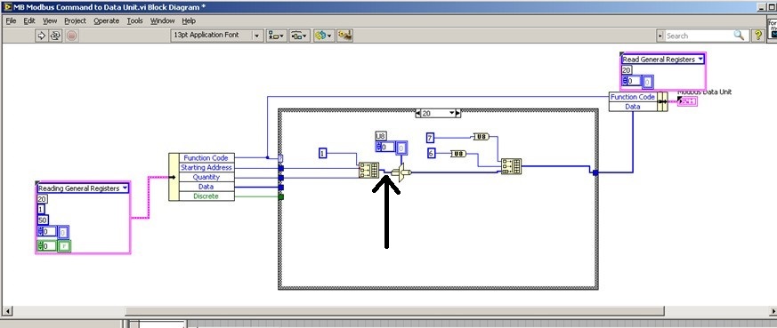
We try to add 20 saving file read function code in order to read the brief in bulk from PLC. We used the modbus for Labview library to communicate with the PLC with Modbus TCP/IP, but when I addes the code function 20 to the cluster of the MB Ethernet Master query entry reading registry Palette entry, the program displays an error. I'll be really appreciated if someone could help with this problem!
We hope all have a good weekend.
Best regards
Sophie
Actually... that is a constraint on the second entry to "build the table? ' It is difficult to tell from the image. If so, what is the data type of this cable?
That must be an array of U16s, because the "quantity" and "home address" are U16. However if the value '1' is a larger data type as U32, labview perhaps at upconversion of the whole table that would result in a larger data set than expected and could cause error 2. You can check on this?
-
Lookout Modbus Ethernet driver for-More PLC?
I see that automationdirect is now out with a CPU of PLC of more that uses material from DirectLogic 205. Their documentation indicates that the new CPU Ethernet port communicates with the protocols that include:
Modbus/TCP Client (master) and
Modbus/TCP (slave) Server
This will be contacted by the Modbus Ethernet Lookout driver?
Yes, Modbus driver support ethernet
We we the ECOM-100 "and" bridge MB
Maybe you are looking for
-
I installed CC Cleaner and ran cleaner and registry. Now I can't use firefox on a variety of sites. They can do, but they do not work properly. I left all the javascripts, but I can still see my destination page (for example can connect to hotmail),
-
Hi all! Even if I take my iPhone with me, training app still will not produce an outdoor performance map? You have to use a third party app?
-
Satellite A200-1QZ: No. HARD drive during the installation of XP
HIII, I have a problem!I have my laptop (satellite A200-1QZ) buythis for everyday, it is with Windows Vista: (((I don't like it! I download driver xp for any material!I would like to install Win XP SP2 cd boot but it's error message, when I access th
-
I had Windows with my laptop. I have the product key on the back. My laptop is broken, so I no longer use Windows on it. Can I use the license on another PC?
-
Path in Windows 7 to save the FONTS?
I can't understand the * path * to save the FONTS. Computer technology has said:Drive CWindowsFontsbut he's NOT here.. !!Only place a RESEARCH showed was under control panel, but which is not just more...Help