Control SynthNV Sig Gen of Windfreak programmatically
I'm trying to programmitically control Windfreak SynthNV Sig Gen and I am not able to communicate and to control the device.
has anyone else has worked with it and managed to automate the control for him? I'm using Labview 2013 SP1 and using the latest version of the document to Windfreak. The Synthizer does not at all entrances.
I worked with the owner to solve problems with Automation control. I coded only the functions I needed. Although tests showed harmonic high, making it unusable for my application. I show the owner how to write a typical labview driver. He had no additional budget to support writing the complete driver. Not a bad product for what it does, a few performance is not high enough for my application.
Tags: NI Hardware
Similar Questions
-
This may sound crazy; but I was looking through methods and solution properties do the following:
- Open a cluster of type strict-def.
- Add an element in a chain of the Combobox control.
- Register the control.
- Close the type-def.
LabVIEW provides the tools to do this within its broad range of pallets?
Second step is easy, as long as the control or parent cluster is not a strict type def.
G.R.
It's tedious, but simple using the VI server / scripting. First of all, make sure that the elements of additional scripts are enabled in the VI server options. Now open the typedef as you would a VI. In the scripts, a typedef is like a VI with no block diagram, only a front panel and control. You can get a reference to the control that you need to change in one of the following two ways:
- Open its containers from top to bottom, using the reference container as the entrance to the owner for the opening of the new control.
- Use of the crosses in the script palette VI
In all cases, after change it, save using recording method tools and you should be good to go. The most difficult part is to get the reference to the control. If you are having problems, let us know.
-
control the visibility of an element programmatically
Hello!
I have a list item and various other elements of text in my form... Based on the value selected in the item list I made some visible and invisible fields. Now, I have to validate the form when I click a button inside. That's the validation should arrive for the only visible fields. How can this be achieved?
Pls help with a solution!
Thanks and greetings
user 10685325Check the [documentation for get_item_property | http://www.oracle.com/webapps/online-help/forms/10g/state?navSetId=_&navId=3&vtTopicFile=f1_help/builtg/getimpro.html]
It returns 'TRUE' or 'FALSE '. -
Rohde & Schwarz SMFP2 control
Hope you can help push me in the right direction, learning exercise for me, non-commercial only.
I have an old & R S SMFP2, with control GPIB described as IEC 625 - 1 (IEEE) 4888 datasheet. I also have a not quite as old NI GPIB-ENET (not the 100 or 1000). This setting is configured with a static IP 10.0.0.200.
Pilots of are all loaded on my version portable 2.2 and map has been updated with the latest firmware A.5 and the 4888.2 NOR getting started Wizard says that everything is OK when I check the installation of hardware and software.
When all connected up to the SMFP2, I ran solution under devices and measurement and Automation Explorer and the interface tree sees GPIB0 (GPIB-ENET) and who can see Instrument0.
Main address is 30
Secondary address 0
Identification of the device has not responded to a * IDN? query
GPIB interface number 0.
At this point all looking good so I will now try to communicate with the Instrument using the Communicator. And it comes to have I can't get reliable answers to the instrument. I copied the sections of the manual here, sorry this is long-term.
Each statement to modify a parameter consists of at least an initial charater (header) and the last character (deliminater). When data on a framework must be transferred, eneter the data bewtween the two characters limiting. All characters are transmitted in code ISO 7-bit ASCII.
When the measurement is complete, the result will be called before a new m, easirement is done, because otherwise the data would be overwritten.
The deliminater for the output is defined in the tester as CR. If you enter a string of fauolty, a service request (SRQ) is sent through the CIS.
The control statements are listed:
The function code
Recieve AR
AM AA
FM (ALBERTA)
CCITT DC
etc.
#
Functions of Code entry
SIG Gen AG123.4567 where 123.4567 is the frequency in MHz
etc.
So I have been tring that I thought maybe the correct things to type in the Communicator send window channels such as:
30 AR
AR
These do not work, but I get better results with 30, or AR, AR, but have to send twice before getting action
Even if I want to put the frequency 30, AG222.4444 sets the frequency after only two starts, I can't question the instrument or reading, he thinks so I do not have the right format.
Can anyone help, if you recognize the former instrument etc.
Please provide a pointer. trying to remember how to program in C will come much later.
If I need to provide more information please, just ask and I will try my best.
See you soon
Adrian
Hi Dennis
I accept that I am not making sense in many. Please bear with me.
Old machine, it looks like that's not 488.2 as he was listed as CIS 625/ieee488 and date from the beginning of the 1980s
The manual says that the deliminater for the output string is defined in the tester as a carriage return.
A default command is AR
or AG123.4567
or BO99
I have been going through some of the documentation and used MAX, where he could find my instrument is attached to the GPIB/ENET and there is a function to communicate with the instrument "Communicator of NOR-488. 2,"where it seems that I can just enter a string and click the write button, or enter a string and click on the button of the query if I want to read data from the instrument.
I could not it works.
AR must switch on the generator of signals, but not entering AR as the chain and hit the write button. For some reason, I tried the combinations that I thought I might have to enter the address of the instrument 30, so I tried 30 AR or 30, AR and strangely if I hit twice the write button, it worked?
That's why I asked the question initially. I've proved since the instrument is fully functional, I now external software that speaks and is fully functional with the instrument. But I would still like to send commands to him myself as a learning exercise.
While going through the site search facilities NOR I fell RPIC legacy interactive control and I will have more success with that.
What he just told me in the documentation, it's even if I put the EOS as 0x000D, I must still enter using \r. So guess what I just tried in the Communicator of NOR-4882, entered string AG123.4567\r click on the write button and the device responds first time every time.
So I guess I'm happy with my first steps.
When I wrote, Communicator, I can't close the sending (0, 0x001E, "BO99", 4 (0x4), NLend (0x01)) I was using spy OR to monitor external software and then enter my strings and see if I managed to get near my captured file.
Anyway happy now all for the want of a \r now give up for the night.
Adrian
-
New remote for Gen 3 apple TV will not pair
Hello all,.
I picked up new remote control for my gen 3 Apple TV on the Apple Store. I followed the instructions by pressing the button MENU and the RIGHT directing on the Apple TV at point-blank range. The LED on the Apple TV blinked his eyes quickly and nothing. I don't have the symbol of the instructions says to wait.
When I press a button on the remote, the LED will blink, indicating the signal, but the Apple TV does not.
I tried to unplug and re - plug Apple TV
Kind regards
Jeff
Have you tried to do a factory reset on your ATV?
-
After effects CC supports the individual control vertex animations?
I would like to animate a single Bézier curve in Adobe Illustrator in After Effects, but I can't seem to find a way to position keyframe each control handle. I want to programmatically control the position and weight of Bezier path of each handle individually over time, so the path blends are not an option.
This feature exists in After Effects or y at - it plugins that allow this kind of control?
Ago, looks like programmatic support for masks is quite limited.
I am, however, see scripts online, which can allow the positioning of the summits by image with scripts, that look like they destroy and recreate the entire mask for each image.
-
calibration of Agilent N5183 Signal generator for specific output level
Hello
Newbie to labview environment! I'm writing a VI to calibrate Agilent N5183 to a specific output. For example if I want to have-4.5 dBm output of my installation (as stated on my electricity meter) I'll have to set the sig gen to say 7 dBm given my losses, etc.
How can pointers, I start to weld it? I think I'll have to create a while loop to check the levels of power, but I don't know how to increment and decrement the amplitude of sig gen and stop at the desired level!
Thanks in advance for any help.
PS: With the help of Labview 2013, on win XP!
mkossmann wrote:
3. adjust the pout to sign Gen to the desired level, while controlling the power power meter
Why is it that step at all? It is not clear from your description, what makes the difference between the reading of the gauge and the output level of the sigGen parameter.
I have done many times. Especially in the RF field, you want your tests to have a certain level of power to the object to be measured. We therefore have to adjust your signal generator to compensate losses in cables, couplers, etc.
To do this, all you have to do is set your generator to the desired level. Then measure with the power meter. Subtract the measurement of the desired and add that much more to the output. Repeat if necessary. I advise to use a conditional TO the loop so that you can easily set a limit to how many times adjust you (I've been in infinite loops due to the weird situations here).
-
Error reading the attached viSA-1073807339 using Subvi, but why?
Hello
First of all, thanks to all who respond!
I read N9020A Agilent MXA Signal Analyzer data. It is successful if a Subvi is used to playback VISA; otherwise "Read Error-1073807339 VISA' rears its ugly little head.» The Agilent gives the message "REQUEST not COMPLETED" just as endearing.
The on error-1073807339 OR Knowledge Base article talks about the need to put an end to the chain of command correctly and explains how to check it by double-clicking the control of chain of command on the front and changing the display of '-' Display Mode of the Codes. I call the VISA Read VI in the block diagram; It does not have a chain of command of front panel control, so I don't know how to apply these tips.
In any event using a Subvi to perform the Read VISA takes care of the problem, but I have no idea why. The VI image that does not work is "Agilent MXA Sig Gen vi.png." A big thank you to Mike on the Agilent forum which provided workaround.
Nina
Mark, Fan of the crows and any other interested person:
I found the error in Agilent MXA GIS Gen.vi. There is typo in one of the VISA WRITE commands. Originally, it was
: MMEMORY
 ATA:? "D:\TEST. PNG"
It should be
: MMEMORY
ATA? "D:\TEST. PNG' (remove: before?)Your comments have been invaluable. Thanks a lot for your help and your patience!
Nina
-
With the help of the external RF signal generator
Hello.
I just want to ask how can I remove the frequency shift if I use an external RF signal generator (instead of the RF PXI-5652 signal generator module). I understand that in the case using the OR to generate RF signals, frequency shift is deleted by setting the same source of reference for the transmitter and the receiver clock (placing the clock source of reference to PXI_CLK of the façade of generation VI and VI of the acquisition).
Thank you very much.
Hi Betty,.
In this case, no changes are needed, such as modules OR still use background clock basket PXI as the ref. clock source If you are still having a frequency shift, you probably need to configure sig gen to lock a clock external REF. Usually, just make the connection of the signal is not enough - you must also indicate the sig gen to use the signal connected to the input clock ref. Terminal
If you use the sig gen as clock source master Réf, connecting the 10 MHz of the gen of GIS at the BNC 10 MHz IN on the back of the PXI chassis replaces the clock native from the newly connected with the PXI chassis backplane, and analyzers are still using the clock background basket PXI as the source clock Ref (no change to the SW settings).
Kind regards
Andy Hinde
RF systems engineer
National Instruments
-
Organize the maximum values of magnitude of several strain gages according to their location.
"There are 32 gauges installed on a 53' (is) 636" span beam which are 20 ' apart. The first pledge is 26 "support. The attached vi gives the amplitudes of the peaks of each pledge individually by changing the columns and rows in the control. Now, these maximum values should be prepared according to the spacing of the beam and join these points with a spline curve.
Open the vi, give the path of the attached excel sheet. Now, in the beginning cluster attribute column 3, 620 to line in the end cluster assign to column 4, 845 to line. Now, run the vi. Assign the columns start and end must be (3,4), (5,6), (7,8) and so forth, to get the maximum amplitudes of each extensometer.
Vlaminck
Greetings Vgrchada.
You can independently change the column and the row of every beginning and end by a beam control based on the name. Look at the example that attached. I changed the star and end constants controls because they will be handled programmatically (so there is no need for human beings humans interact with them) always use for the line start and end values, because there is where all the data are. As for the columns, use the iteration of the loop counter For (with differences appropriate, while it starts where it should) another possibility is to build a table with all indexes and use the property auto-index of the loop For (this in the case where the columns are not side by side).
I would like to know how it works. (I have not tested this code, but the principle should at least help you find your way)
Kind regards.
-
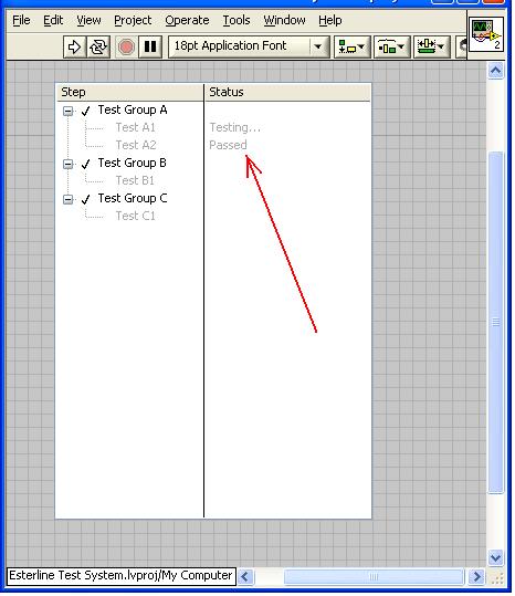
Hi guys,.
I'm new to the tree control. I'm trying to programmatically change the State of the second column without changing the text of the left cell in the control (see attached photo). Can you please point me to the right direction? I use Labview 8.5. Thank you.
I am fairly new
Hello
There is a feature in LabVIEW, called property node. With the property node, you can change the front panel objects programmatically. You can make the property node with a right click on the object you want to change by programming and will create > property node and then you have all the properties of the selected object, you can programmatically change. When you created the property node, you can change access (read/write) with right click, and then you choose change all to write or modify To Read, depending on what you have chosen.
In your case you will need 3 properties:
Active cell > column Active - sets/bed number of the current column number
Active element > line number - sets/bed number of the current column
Active cell > String - string of the element sets/bed
If you have any questions feel free to ask.
Respect,
Gregor ring
-
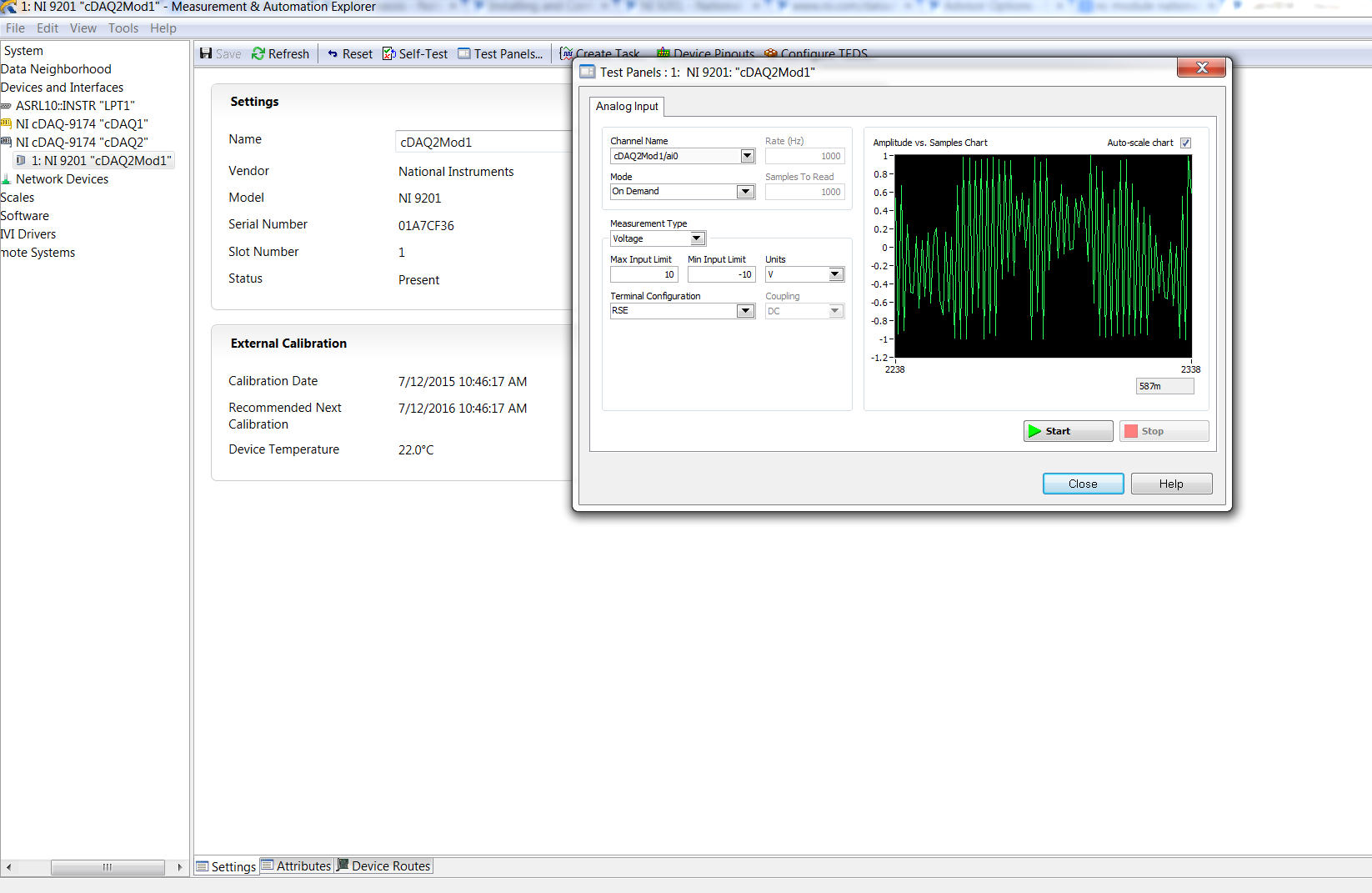
Problems with the cDAQ-9174 and NI 9201 Module
Hello world.
I'm testing a material that I just got and I have some problems and questions, if anyone can help that would be great.
First of all, I couldn't work in the data sheet what were the NC and COM ports:
http://www.NI.com/datasheet/PDF/en/DS-184
I try to connect to a signal generator and simply display the signal in MAX on the test Panel, but the signal is not look right for the moment. The following illustration shows what I see of what is supposed to be a 100 Hz sine wave of the SIG gen 10V
Hi Dawud,
NC being 'not connected' - what information do you need?
-
Hello
I was wondering if someone can help me configure this gps "spirent gss 6100", sig gen with the use of usb?
I could not find any drivers and I was wondering what it'll take to get communication.
It has a USB interface...
He is unresponsive to the * idn?, always, it expires.
It does not appear in Max.
can anyone help?
Thank you.
Hello once again.
I want to tell you, I managed to solve the problem.
want to thank everyone, anyway.
so, thank you.
-
Try using VISA series decimal command sent to the third sig gen via RS232. Here is the command to be sent by the PXI system to the sig gen.
It is the command and the checksum. The Assembly is USB UART bridge.
1.) decimal: 115 48 54 56 68 85
Greg B
Hello Greg,.
If you try to do, but how you try to do this? You see errors? You know not even know start? Please give us some details on what is your situation so that can offer more advice. Thank you.
-
4th gen Siri remote control has stopped working
I had my 4th Gen Apple TV since November 2015. Last week noted that the TV shows and movies are glitching but if I do a reboot on the apple TV everything works fine again and have to do it every day.
Today the Apple TV remote was working fine all day then when a finished film went to for use and there was flashing reaction flights when I pressed one of the buttons. At first, thinking it was maybe needing a charge on the charger. A few hours later I returned to use the remote and it still doesn't work do not at all. I went into the Apple TV menu using a remote old money I thought that I would check how much fresh had the remote and I went for the remote controls and devices > BlueTooth remote control is more is listed and the dial connection was but would not connect to the remote control?
I tried to reboot that fixed the glitching to see if maybe he would take the remote, but still nothing. Does anyone else have this problem?
Try to re-twinning of Siri remote:http://help.apple.com/appletv/#/atvbc9953e63
Maybe you are looking for
-
Error 80246008 designates in the Background Intelligent Transfer Service when I try to turn it on I get the error 126 that the specified module cannot be found please help thanks
-
I have an old xp laptop computer with a product key... it's broken. is an iso file of windows xp with sp3 can I download and install? Windows xp home
-
HP PSC 1400: the printer does not print with new ink supply
recently bought a mac book pro with OS X 10.11 El Capitan. Attached is my old HP PSC 1400 for my print/scanning works. System is automatically downloaded and installed the driver. The scan function works well, but I was unable to make an impression.
-
Windows 7 - USB keyboard and mouse do not work once Windows starts
The following happens occasionally: The keyboard works perfectly in the BIOS, the post OFFICE and when the Windows 7/64 Ultimate starts (I can tell the [Numlock] led shines). But when you see the Windows login screen, both, USB keyboard, USB mouse an
-
Wie kann ich bei den Adobe Acrobat Reader automatischen Update löschen oder unterdrucken
Hello community,Wie kann ich bei den Adobe Acrobat Reader automatischen Update löschen oder unterdruckenDanke für die HilfeGruss Heinz