cRIO communication as a PLC with NOR-OPC-Server
Hello
I have the task to implement communication between multiple cRIO and NOR-OPC-server. The OPC OR server should act as a data manager for a complex interface.
I tried the NO-OPC Server and I managed to communicate with the server OPC-NOR as OPC-Client in Windows using a server IO and shared Variables. But the task is to do it on a cRIO. I tried to open a data from a cRIO socket connection to the NOR-OPC-server using a specific URL by using "DataSocket select URL.vi." But as long I do not activate the simulation in the OPC Server - OR-I get errors on the data socket connection opening. If I activate the simulation, which is not the solution, I can write data without error, but the quick OR-OPC-Server Client sees no change for the data label.
I have the feeling that I am not a good way to get this working. Is there anyone with experience with this? Is data taken one possible at all? It is possible at all? I have to put in place a cRIO-OPC-driver?
Thank you.
Hello
I found the solution in this article:
http://www.NI.com/white-paper/7451/de#H36
Thx for your help.
Tags: NI Products
Similar Questions
-
Application built with an OPC Server
Hello everyone
I build the application on the development using wich S7 computer - connected to the OPC Server 1200
and I want to build the application to run the VI on another PC without installing labview, however when I finished to build the application with the installer and install the application on another PC it cannot connect to shared variables so I installed an opc Server ON this machine and add the server to the software mutual FUND that contains tags and variables
but it is not also connect to the opc Server
So how do you run the application on another PC with an opc Server!
How the VI to use a specific opc server on this PC with no labview?Hello
What do you call the OPC Server? You are creating a mutual FUND of LabVIEW client and linking to the shared variable? If this is the case while you use the LabVIEW DSC module and it works very well in the development environment.
However, every time that you deploy (creation of executable or installer) a VI using DSC module, you must have a license to run on each computer that runs the executable file. http://sine.NI.com/NIPs/CDs/view/p/lang/en/NID/210561
the alternative would be to use the socket api in LabVIEW to call the server.the attached VI OR OPC illustrates how.
I hope this helps!
-
How to install the OPC Server with the Application Setup
Hi all,
I make the datalogging progam in the PLC via modbus communication using the OPC server.
1. I got configer the opc via the Project Explorer client some time it works perfectly, but when I run it by the next day, he cannot communicate with an OPC server but the OPC server is to communicate with the PLC. When I right click on the properties of the customer e/s in the exploer project opc and make any change and still run the application it works where is the problem.
2. the second problem is by building the installer that will be installered to my PC targate OPC server. Bacuse I had installed the application on the computer target just for testing but OPC Server havn't installed even if there is no option for adding the OPC while bulding server.
Serdar, SALVATION
Thanks for the reply I saw your example, your idea is ok, but if I have more then 100 and with different types of data tag then where is the problem to manage all these tags.
Now, what I had done I took the express to create vi or configer server I/O and give the name of the process even as file name as opcdemomo and same server name reference in the Project Explorer and restart and scream in low tow and three times it works I havn't get any problem.but which is not the right method.
-
Encoder interfaced with NOR-9401
I bought a coder who has open collector and resistance to pull-up 3.3 kohm (TTL) logic output.
The encoder comes with four sons: power + 5V, GND, channel A and channel B. channel A and B are logic output.
Channel A and B are connected to the OID of NOR-9401 which is mounted on the cRIO.
A standard VI for encoder counting is used and compiled under the FPGA environment.
During the measurement, I have observed that there are number of significant loss in both directions encoder.
I don't think that there is a problem with VI like I used it several times on the encoders with output RS422.
Is there a problem with my current encoder with respect to its electrical interface with NOR-9401?
Thank you.
I don't think that there is a problem with pull-up resistance. Even if the digital IO ports have their own resistance to pull-up (usually of the order of 4.7kOhm - should be included in the manual), the power to be handled by the circuit of encoder output transistor is about 2mA. -Check your configuration for a correct connection GND. You must connect the encoder directly power GND to DGND to the printed circuit board Terminal.
-
Using PCI-8532 with NOR-DNET 1.6.6 / NOR-DNET 2.0.2
I have a PC with the following configuration test set-up:
- Card PCI-8532 DeviceNet
- Windows 7 Enterprise, SP 1
- LabVIEW 2010 Runtime
- NOR-DNET 1.6.6 with MAX 5.0
- No environment of LabVIEW Development
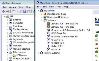
- PCI-8532 isn't available in MAX and Windows Device Manager indicates the card as "PCI Device" with an exclamation mark.
Here is a screenshot of Windows and MAX Device Manager:
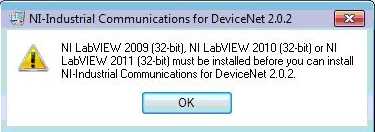
I can't install the NOR-Industrial communications for DeviceNet 2.0.2 on this computer because I get the following error:
Well, I have two questions
- How can I install and use the PCI-8532 and see with NOR-DNET 1.6.6? If this is not possible:
- How can I create an executable file on my system (portable) development with LabVIEW 2010 or 2011 LabVIEW and run this executable on the test set-up. I currently have on my development system:
- Professional 2010 LabVIEW and LabVIEW 2011
- NOR-DNET 1.6.6
- No hardware OR at all
- I have to install the NOR-Industrial Communications for DeviceNet 2.0.2 on my laptop (my development system)
- This will interfere with my current NOR-DNET 1.6.6 and then I select which driver to use at compile time
Thank you
Nick
Nick HY,
No, it is defenitely not a replacement yet and I will work with our Web Department who make clearer on our web page.
The development of the new API is pretty well done, but based on your feedback, we are planning to improve compatibility, so you can for example use the old APi 1.6.x and the new APi of 8532 on the same machine, so you can use the old and the new material on this same machine. Which would be important for you?
For the moment we intend not to allow only one type of material on the same machine to save you development time. Let me know what you think.
To clarify the situation today: The InCOM for Devicenet component is not part of LabVIEW. It's just a very simple means of communication with the I/o variables and blocks of function for the MS. The driver should install fine even without installed LV. The error message is quite a Bug on our side, and the solution would be to use the Builder installer LV to create a new installer that can install 2.0.x Incom Dnet driver without having installed Lv.
And today, you should be able to have the 1.6.x both pilot 2.0.x in parallel and use the API 1.6.x with old boards yonce and the variable approach of IO 2.0.x with your new Board of Directors.
I'll keep this post updated as soon as we have a stable Beta available I'll post something.
DirkW
-
Support for alarms diagnosis field according to FF - 912 with NOR-FBUS Configurator 3.2.3
I tried to control the utility alarm monitor and diagnosis field according to FF-912 alarms since a FF camera H1 with NOR-FBUS Configurator 3.2.3.
Alarms standard block for example in the case of a change of parameter are monitored in the alarm monitor.
Field diagnosis according to FF - 912 alarms are not controlled.
Are field alarms diagnosis according to FF - 912 took supported by the NOR-FBUS 3.2.3 Configurator. or something special to do to activate the analysis.
If not, what tools or host systems are available for monitoring these alarms?
Alarm in the software OR-FBUS monitor doesn't have a field of diagnostics alarms. You can try to use NOR-FBUS C API nifWaitAlert2 to monitor this alarm. We will find the detailed description of the API OR FBUS Hardware and Software User Manual Chapter 6.
-
connect labveiw 8.2 with nor pci-6251
I have no pci-6251 and its cd driver with labview 8. How can I connect the daq with labview 8.2 and run programs
Hello
I can't download the driver of NOR-DAQmx 8.7.1, connect labview 8.2 with NOR-DAQmx PCI-6251...
Why?
Please answer...
-
problem with loopback test base with NOR-6008
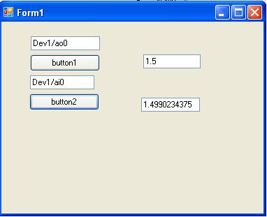
I recently started to use DAQmx in c# .NET 4.0 with NOR-6008 USB DAQ. I tried a loopback test by connecting output to an analog input analog and tried readign the signal from the output to the entrance but did not send the signal (or maybe a problem with the code). The analog input readign reads a random value rather than the value entered by the user for the output. I connected ao0 and ai3 on data acquisition. Here's the code.
private void button1_Click (object sender, EventArgs e)
{
Task analogOutTask = newTask();
AOChannel myAOChannel = analogOutTask.AOChannels.CreateVoltageChannel ("Dev1/ao0", "myAOChannel", 0, 5, AOVoltageUnits.Volts);
AnalogSingleChannelWriter writer = newAnalogSingleChannelWriter (analogOutTask.Stream);
Double analogDataOut;
analogDataOut = Convert.ToDouble (AnalogOut.Text);
writer. WriteSingleSample (analogDataOut, true);
}
Private Sub button2_Click (ByVal sender As Object, EventArgs e)
{
Task analogInTask = newTask();
AIChannel myAIChannel = analogInTask.AIChannels.CreateVoltageChannel ("Dev1/ai3", "myAIChannel", AITerminalConfiguration.Differential, 0, 5, AIVoltageUnits.Volts);
AnalogSingleChannelReader reader = newAnalogSingleChannelReader (analogInTask.Stream);
Double analogDataIn is reader. ReadSingleSample();
AnalogIn.Text = analogDataIn.ToString ();
}
Hello
I built an application using your code (with task.verify) and it works beautifully.
Have you tried different channels of inputs/outputs?
Curt
-
Hello everyone,
already, I asked once about the creation of PWM with hardware. And I was pleased with the response. But now I found 94xx Series-USB OR hardware. Here are the materials of high-voltage-Digital i/o. If any of you have already met with this one, would like to hear your conclusion about them. Would also appreciate if you could answer my question:
Is it possible to create a PWM Signal with NOR-USB 94xx?Thank you
Grigory
Grekov wrote:
I'd be more interested in the USB Module NI 9472 USB connection. Because it's the only one that would match my request.
What is your application?
Why don't choose you something in this list.
If your condition is out to say 24 v PWM signal... you can also plan to use a custom circuit intermediate, not only to scale the output signal of the device (at 24 v) but also the reader following circuit.
-
Clock and hw external trigger with USB-6210 on Linux with NOR-DAQmx Base?
I have two devices USB-6210 I need to synchronize so that they both collect data exactly at the same time. I was told by support OR I can send the clock off Dev1/PFI4 and have the two USB-6210 s read the clock in through their own PFI0. I also want to trigger data collected for each device by sending a trigger off Dev1/PFI6 and have two devices to receive the signal on PFI2.
All my attempts to try this are filled with error messages and my research online seem to say that's not possible with USB devices on NOR-DAQmx Base 3.4.0f2 on Linux.
I "ve tried using example AI programs and those who do not seem to work either for external clocks. Here is the code I tried:
#include "NIDAQmxBase.h"#include

#define DAQmxErrChk(functionCall) { if( DAQmxFailed(error=(functionCall)) ) { goto Error; } }

int main(void){    // Task parameters    int32       error = 0;    TaskHandle  taskHandle = 0;    char        errBuff[2048]={'\0'};    int32       i;

    // Channel parameters    char        chan[] = "Dev1/ai0";    float64     min = -10.0;    float64     max = 10.0;

    // Timing parameters    char        clockSource[] = "/Dev1/PFI7";    uInt64      samplesPerChan = 1000;    float64     sampleRate = 10000.0;

    // Data read parameters    #define     bufferSize (uInt32)1000    float64     data[bufferSize];    int32       pointsToRead = bufferSize;    int32       pointsRead;    float64     timeout = 10.0;

printf("Calling CreateTask...\n");    DAQmxErrChk (DAQmxBaseCreateTask("",&taskHandle));printf("Calling CreateAIVoltageChan...\n");    DAQmxErrChk (DAQmxBaseCreateAIVoltageChan(taskHandle,chan,"",DAQmx_Val_Cfg_Default,min,max,DAQmx_Val_Volts,NULL));printf("Calling CfgSampleClkTiming...\n");    DAQmxErrChk (DAQmxBaseCfgSampClkTiming(taskHandle,clockSource,sampleRate,DAQmx_Val_Rising,DAQmx_Val_FiniteSamps,samplesPerChan));printf("Calling StartTask...\n");    DAQmxErrChk (DAQmxBaseStartTask(taskHandle));printf("Calling ReadAnalogF64\n");    DAQmxErrChk (DAQmxBaseReadAnalogF64(taskHandle,pointsToRead,timeout,DAQmx_Val_GroupByChannel,data,bufferSize,&pointsRead,NULL));

    printf ("Acquired %d samples\n", pointsRead);

    // Just print out the first 10 points    for (i = 0; i < 10; ++i)        printf ("data[%d] = %f\n", i, data[i]);

Error:    if( DAQmxFailed(error) )        DAQmxBaseGetExtendedErrorInfo(errBuff,2048);    if(taskHandle != 0) {        DAQmxBaseStopTask (taskHandle);        DAQmxBaseClearTask (taskHandle);    }    if( DAQmxFailed(error) )       printf ("DAQmxBase Error %d: %s\n", error, errBuff);    return 0;}
When I run the resulting program, I see this:
$. / acquireNScans-ExtClk
The CreateTask call...
Call for CreateAIVoltageChan...
Call for CfgSampleClkTiming...
Error-89136 DAQmxBase:route specified cannot be satisfied, because the hardware does not support it. For example, a clock and a trigger can be imported via one of the PFI lines by using a USB-6210 on Linux with NOR-DAQmx Base? A clock and a trigger exportable via one of the PFI lines?
If so, does anyone have the code example illustrating how to do this, or can you at least tell me the names of the lines ("PFI0/Dev1" or other) so I can try again?
Clues or suggestions would be helpful.
Thank you
-Tom
The clockSource in the example specifies an output rather than an input channel channel. Change source "/ Dev1 / PFI0" solved the problem.
Please close this post.
-
How to calibrate the PCI-6110 with NOR-DAQmx
Hello
I am a new user of the PCI-6110 Council tries to run the calibration using LabVIEW procedure. I look at the document "Calibration" on the page of the manuals for the Board of Directors,
http://sine.NI.com/NIPs/nisearchservlet?nistype=psrelcon&NID=11888&lang=us&q=FQL: 28locale % 3Aen % 29 + AND + % 28phwebnt % 3 A 1081 + OR + phwebnt % 3 A 7075% 29 + AND + 28nicontenttype % 3Aproductmanual % 29 + AND + % 28docstatus % 3Acurrent % 29% 20RANK % 20nilangs: en & title = NOR + PCI-6110 + manual
One of the first steps in the document is to call the AI_Configure command to set the input mode, beach, etc. I'm using LabVIEW 8.5 with the NOR-DAQmx software, and I can not find the command (which, in LabVIEW, seems to be "AI Config.vi") anywhere. The calibration paper was written in 2003, and I gather from Google searches (please, correct me if wrong) that this command is actually a part of NOR-DAQ traditional, who was replaced by driver OR DAQmx.
My question is this: what is the equivalent to AI_Configure command in the latest software? Is it perhaps a subsequent document describing how to calibrate using NOR-DAQmx?
Thanks much for any help.
Tom McLaughlin
Hi Tom,
The calibration Procedure series B, E, M, S, which is also linked from this page, describes how to calibrate the PCI-6110 with NOR-DAQmx.
Brad
-
Hi all
I would like to know if I can use or pci-6229 with nor-soft scope? I found no information on it.
Thank you
Dima.
-
Communication of Labview (OPC client) to the citect (OPC Server)
Dear members,
I want to access the data (from the Labview 8.6) which is on a PC of citect. As I am not aware of citect, can someone explain me how to do this, if you had experience?
Using the mechanism of data taking, I think we can run, but what kind of arrangements are to be made on the side of citect. Is it likely that an OPC server to perform citect side, so Labview can act as an OPC client? How can I implement this? I went through examples OR Client.vi, Browse to Item.vi OPC OPC Demo.
Someone with a 'Labview' experience - Citect here?
some ideas please.
Thanking you.
-
I ran the System File Checker tool analysis. Response has been no problem with the configurations. Also, I did uninstall and reinstall. I keep getting the message: "a network error occurred during communication with the game server. "Error code: 0 x 80041006 ' this error message occurs on all the computers I own.
Actually, no, the answer in the links were also less than helpful... suggested this, that. Things that I had already done b4 posting my question.
More funny: after that I posted my comment about the fault is not not in my machine and those of thousands of others, but in MS, spades servers suddenly started working again. Coincidence? No doubt, but still... -
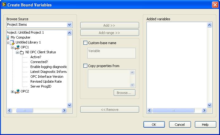
problem with a 2012 opc Server
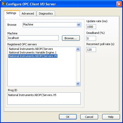
I use LabVIEW 2010. I installed OPC Server 2012. Configure DCOM. Create tags OPC Server

Create the project and create opc client
But I don't see the tags in the variables:
Can someone help me, I don't see why tags?
What is under the OPC2 folder?
Also, I checked my 2012 OPC Server readme (start > all programs > National Instruments > 2012 an OPC Server > Readme) and he said:
"You can use the OPC servers OR with the following software applications:
- LabVIEW 2011 SP1 full or Professional Development System
- LabVIEW DSC Module 2011 SP1"
This may mean that it is not compatible with your version of LabVIEW.
Maybe you are looking for
-
HP Officejet 7410 language problem
I'm going to put in place this wireless (a HP 7410 all-in) and the display is in Japanese. How in the back to English? Tried all I know and nothing.
-
Creation of graphics/field/pirctures - HELP
My program collects sampled data and an interval defined by the user. It is then a simple regression line y = m * x + b where m = Cov [x, y] / Var [x] and b = bar - y - m * x - bar. After these calculations are down I want to draw the diagram of di
-
disable the internal microphone
Lenovo x 201 2985 F4U is it possible to disable the internal (built-in, integrated, whatever it's called) microphone on this unit? I have not been able to find a way without disabling the whole card.
-
Refused to use the icon for BBM chat. ? * everything is less a dumbed down user experience. I guess I'll create an icon of the Virgin in its place Ery-happy:
-
Compaq presario cq56-129nr crashes in silent mode, or sometimes with a loud buzzing noise. A ran the recovery starting test and received the error code short dst hard drive 1 failid product 9fwk1h-5hn727-xd003 u683ua #aba the pc is of course not unde