cRIO input voltage level
I use a cRIO 9004. I noticed it has a chassis temp option. I was wondering if there was a way to find the input voltage. My unit is battery powered and I knew my batery voltage level. I'm doing some kind of a voltage drop detector.
I am a novice to Labview - I'm sorry if I missed something obvious.
Thank you.
You have not forgotten anything. Currently, there are no i/o chassis set up to read the voltage on your power supply. You'd have to do is to use an analog input module to read the voltage yourself.
Kind regards
Tags: NI Hardware
Similar Questions
-
digital input voltage measurement
Hello.
I develop software for a test bench.
(the material has been developed in the past by someone else, and I have to use this material now)
I have to read some digital data with one nor usb 6501.
I measured the voltage on pins levels and realized that to logic 1, I get about 4, 7V, logic 0 about 3, 5V (who, after having converted to digital, is always 1).
You have an idea how I could fix this?
I thought that if I could somehow put the analog value of voltage on the PIN, the problem would be solved, but I n ' not know if it is possible.
Thanks in advance.
Katona
Hello
the 6501 low input voltage (false logic) is 0.8V and high voltag of entry is on the order of 2.0 v to 5.8V. You must use an electrical circuit or device with an analog entry order to solve this problem.
What do you think of "Schmitt Trigger"
http://en.Wikipedia.org/wiki/Schmitt_trigger
Concerning
Rüdiger
-
Using the DAQ USB-6009 meter and an analog input voltage at the same time.
Hello
Currently, I'm reading the two channels of voltage with the USB-6009. It happens that one of the channels is the output of a digital coder, and it would be much easier to use it directly to the PFIO entry that is defined as a counter. The problem I am facing right now, it's that I can't use the DAQ Assistant to use the analog voltage to a channel and the digital channel counter at the same time. Once I put the DAQ Assistant to read the input from analogue voltage, I won't be able to add analog inputs. And as I put the DAQ Assistant to use the PFIO as a counter, I can add more entries to read analog voltage is.
I wonder if it is possible to solve this problem using the lower level data blocks? Another solution would be to read two channels in analog input voltage and that the use of Matlab to process data resulting from it, since I was not able to do the counting to work simultaneously with the acquisition in Labview to impulses.
Hope you guys can help out me.
Thanks in advance.
Using a simple wizard of DAQ is incorrect. You need one to acquire analog inputs and one for the meter.
-
Tab 2 of the A10 input voltage?
I wonder if tab 2 a10 should work abroad where the electricity voltage is 220 instead of 110.
Any help would be appreciated. Thank you!
You will be fine, that the C - P35 AC adapter is bitensión with 100-240V input voltage range
Output 5.2V 2A.
-
Q150 input voltage? Help, please
I sent twice, named Sales and no one yet knows the Q150 input voltage...
Can someone view detailed list of specifications of Q150 which includes its input voltage? Or anyone who owns a Q150 can look for me?
Thank you
Hi ciguli and welcome to the Lenovo user community!
Said manual material: 100-240v AC:
http://consumersupport.Lenovo.com/us/en/Userguide/Guide_list.aspx?CategoryID=741912
-
Voltage level of setting Digital Out in NI 6221
Hi all
I work with a NI-6221. I wonder if it is possible to change the voltage level of the digital channels? CurrentY I use "Digital Bool 1line 1 point" as my writing DAQmx.
Thank you
Saridar
No, the outputs are only ttl levels.
-
HOW to make NI6537 work 2.5 v voltage level
Hi all
I just check on the datasheet of NI6537, it shows this work card to 2.5V 3.3V kinds of digital output voltage levels.
But the default setting is 3, 3V. So, how do we define to 2.5 v (to the digital output) (using C++).
I had once a function:
Int32 DAQmxSetDigitalLogicFamilyPowerUpState (const char deviceName [], int32 logicFamily);
Defines a family of digital logic to use when the device turns on.
But it doesn't seem to work in my codes. Anyone know how to set up?
Thank you
Liang
Hi Liang,
Also, if you want to change the level of digital logic of your output from 3.3V to 2.5 v, take a look at the following example: static adjustable logic level digital output
-
Analog input voltage assistant DAQ
Does anyone know why theres error when you use two assistant DAQ (in a while loop at the same time) for reading of the analog input voltage?
There is not a problem if you use a wizard to data acquisition for analog input voltage reading simple.
If you get an error, wouldn't it useful that you have told us what it was, we may be able to explain it?
I'm guessing that you have error-50103, and if you look in the forums for '50103' (leave out the negative sign), it will give you the answer for this question has only requested thousands of times before.
-
Configure the input voltage range
I use an NI USB-6221 with SignalExpress 3.0 card.
The Spec for the 6221 map specifies 4 analog input ranges of +/-10V, 5, 1, & 0.2.
My question, how is the range of input voltage on the map on one of the beaches specified?
The closest thing I can find in SignalExpress is step 'DAQmx aquire', looking at the tab "configuration" of "Configuring the stage." There is a group called 'settings', there are areas of maximum and minimum input Signal, but context-sensitive help indicates that it is expected for the channel after the scaling values.
I also looked into MAX, but I see no way for me to directly configure one of these ranges.
Can someone explain how this works?
Mike
You look at the right thing. When you specify the min and max, the DAQmx driver and then automatically selects the best range of this signal. For example, the Council supports + /. 1 + /-1, at ± 5 and ± varies from 10 volts and a jury of 12 bits. If you enter max/min to + /-2, the jury will be set to the +/-5 volt range. Your resolution is then 10 (oscillation of the total voltage) volts divided by 4096 (2 * 12).
If you were using LabVIEW, you can get the actual voltage selected range by using channel properties DAQmx AI. Rng.High and I. Rng.Low. If you specify a min and max that is less than the amplitude of the real signal is greater than the actual scale used, then you cut your input signal. DAQmx does not have an autoscale. Take a look at Page 4-2 in the Manual of the M series.
-
USB-6008 LABVIEW 8.2. SINGLE CHANNEL WITH DBL INPUT VOLTAGE OUTPUT COMPARISON
I AM WRITING A PROGRAM THAT USES A SIMPLE USB-6008 ANALOG INPUT CHANNEL. I WANT TO READ CONTINUOUSLY THE VOLTAGE FOR 60 SECONDS. I WANT TO COMPARE A TENSION FOR THE PREVIOUS OF THIS SAME CHANNEL VOLTAGE, MAINLY FOR THE PERIOD OF TIME MAX VOLTAGE GIVEN, THEN GET A FINAL VOLTAGE READING. THE OUTPUT OF THE VI IS A DBL. I WANT ONLY TWO TENSIONS OF EXPORT TO EXCEL. TO SAVE TIME, I KNOW HOW TO EXPORT. CAN SOMEONE HELP ME WITH THIS ONE.
VI needs an register shift related to the Max & Min function. The current value would be the entrance is and the entrance of x is the left shift register. The max value gets wired for the shift register to the right. Don't forget to initialize it. The output of the shift register is the max you would write and the value of the DAQmx Read out of the loop of wire will give you the last reading.
Your waiting for 45 seconds makes no sense since you said that you wanted to read continuously. You also said that you wanted to read 60 seconds and all this logic is missing. A simple function of time elapsed, it's all you need.
-
Custom control with couple or the input voltage system
Hello
I'm relatively new to LabVIEW and this is the first time that I'll use for an application of movement. I have a controller/chassis cRIO-9074 with a few modules NI 9514 IO, servo motors and drives, and I'm trying to do is to use a custom control in my system (a sliding mode control law) to generate the signal for the movement of the engines. I was able to produce a movement OR softmotion but so far I've been able to produce with position, speed and acceleration as inputs and to optimize PID gains. What I want to do is to send commands to torque or tension from the entrance of my right to command control is torque for motors. What I was wondering is if it's possible with the components that I use now and if someone could direct me to useful articles or books that can help me.
Sorry if is a noobie question but I only worked theoretically with systems of control far and I didn't simulate the results with matlab before that. It is the first time that I had to get the experimental results to validate my proposed control right. Thanks in advance.
Hi,.
This may be possible, but since sending the commands of torque or tension directly don't are not supported in scan mode, you can use your 9514 FPGA mode.
This link describes the components needed to run the FPGA device.
You should be able to find examples in the Finder for example NEITHER, but here is an overview of the use of FPGA that can be useful as well.
-
Inputs voltage DAQ affecting each other and the camera, they save you of
Hello world!
I use ELVIS II + and LabVIEW 2012 to register a device with a resistive sensor voltage (voltage see with ELVIS II.jpg for VI). The device (device + ELVIS II Schematic.jpg) measure the voltage across the resistive sensor and is controlled by a msp430. If the msp430 believes the change of voltage of the probe is above the threshold, a light is on. There is a motor function on the device and the LED is normally not on when the engine is turned on. I found that registration with the acquisition of data affects the behavior of the device. The reasons daq hardware and devices are connected. During data acquisition does NOT record, gross and analog sensor in tensions are constant (and the LED off) while the engine is on (Figures.doc; (A). when data acquisition IS recording, the engine power seems to distort analog in / raw voltage of the sensor causing the LED lights up (Figures.doc; (B).
The trials that did not issue (led on while engine):
1. registering with new ELVIS II + DAQ
2 separate inputs raw and engine sensor on data acquisition
The tests which fixed the problem (any engine LED is off):
1 grounding gross and/or motor sensor
2 separate channels of raw and engine sensor in the wizard DAQ (Figures.doc; C: shows engine and raw sensor separated by A_VCC. Figures.doc; D: where engine and gross sensor are side by side). I don't know why the order of the channels in the DAQ assistant would affect the behavior of the sensor signal.
Any advice on this problem and ways to troubleshoot/potential long-term solutions would be greatly appreciated!
Thank you!
If your device has no acquisition of simulteanous, then each channel is multiplexed in the ADC. It has a capacity of entry inside your device, which gives it a 'memory '. If the voltage stored in the capacitor is not unloaded a scan before the next scan starts, then the second scan will "remember" is the result of the first analysis, give you really weird problems. More source impedance on the canal e e greater probability that the signal from the previous 'remembered '. That's why the order of the questions, the higher source impedance going first.
-
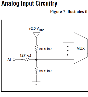
Cut-off for the 6008 analog input voltage
I am using the analog inputs NI USB-6008. The specification says they have a 144 k ohms input impedance. But it does not say what is the cut-off voltage. If you leave a disconnected and measure the voltage you will get 1.4 volts. So I guess it's the cut-off voltage, but it is not spec'd.
Someone agree that these Amnesty International isn't terminatied by 144 k - ohms to 1.4V? Is this in the documentation somewhere?
Figure 7 on page 16 of the NI USB-6008/6009 User Guide and specifications shows the strange input of this unit circuit.
Lynn
-
What is the input voltage max of the motherboard on Satellite 1110?
What is the maximum voltage for the motherboard in the Satellite 1110 please?
Because my current cpu (1.5 ghz celeron) is 1.025 volts and I would like to change the processor
something faster (cooling will be treated with btw XD)
The only problem being that the new processor needs 1.3 volts to run.Any info wud b appreciated
Is that not every processor is compatible with the motherboard.
1110 series computer are supported on the Intel Mobile Celeron processors up to 1.8 GHz.
Other processors are not compatible and the laptop won't work with faster processors. -
SCXI 1338 - input voltage range
Hi all
I use SCXI-1338 blocks in modules SCXI-1125. Currently channels measure currents in the 4milliamps range at 20 Ma.
I'll be able to measure signals VOLATGE by connecting to the SCXI-1338 module, and what is the range of acceptable voltage AC or DC? And also should I do everything
changes in the SCXI-1338 module block in order to measure the voltage signals? I want to measure 20V DC signal controlled by a PLC.
Thanking you.
Well, what it really comes down to the Ohm's law in the end. V/r = I, you'll 20V/250Ohms = ~ 80mA which is well above the limit of the 1125 and the 1338. I recommend you either go with the voltage attenuator 1327 or you could possibly do external cables to a voltage divider. If you place a resistance of 1kOhm serial then your V/R = I equation turns into 20V/1250 Ohms = ~ 16mA max. To find your tension, you must create a custom scale to account for this new resistance. However, given that most of the resistance will be a mistake, it would be better if you measured the resistance of the circuit using a multimeter or an equivalent for an estimate more precise of the real resistance.
In the end, the 1327 is going to be a cleaner solution, but you can also go the road of voltage divider if this does not work for you.
Lars
Maybe you are looking for
-
encrypted backup MacBook HD unencrypted Time Capsule
Hello I got an error message on my MacBook that I tried to back up a hard drive encrypted in a clear time Capsule. How can I handle this?
-
How to use the recovery to the Satellite A100-216 CD
the first step on this cd said... 1. Insert the first disc in the drive and turn off the computer... so is he saying that I insert the cd when the computer is on and then it once I put it full?
-
There used to be a FAQ in Apple communities with detailed information on the use of time machine. This information is always available? One person maintains this info? Thank you.
-
Suggestion of OS for an old desktop PC
Hey,. I have an old desk in my house. It worked on Windows XP (SP 2), but since Microsoft ended its support I think to change the operating system. It has a processor Intel Celeron 2.66 GHz, 1.5 GB of RAM and 320 HARD drive. You guys you will suggest
-
Hello. When I update my database, it always hung by prepare()! After 30 seconds, close() finally called. Exception will be throwed if I operate the database during the second 30 before its closure. How can I overcome this? Code: public void update(St