CROSSTALK in NI 9215 signals
I currently use a NI 9215 module with BNC terminals to read the outputs of two different types of voltage sensors. Probe is a probe differential o-scope (Tektronix P5200A) which has a rejection of sound very good, while sensor B is a shunt isolated hall effect measurement using a LEM lv20-P and a custom PCB, which has a considerably lower noise rejection. Noise in the circuit to be measured is mainly the result of a H-bridge Inverter circuit that goes to 10 kHz. A picture of two sensors measuring the same signal displayed an o-scope is shown below with the sensor signal on top and B sensor on the bottom.
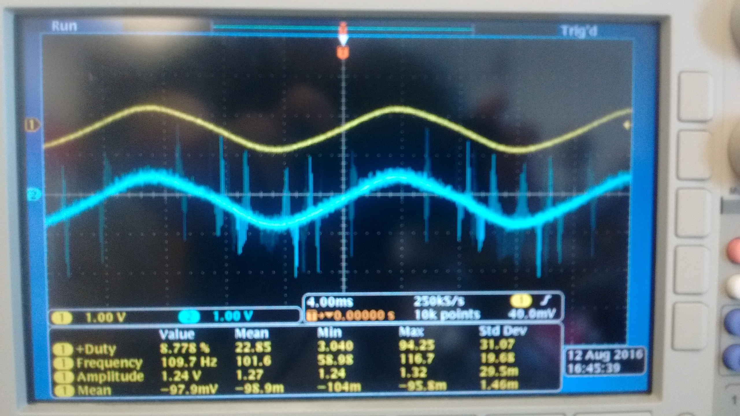
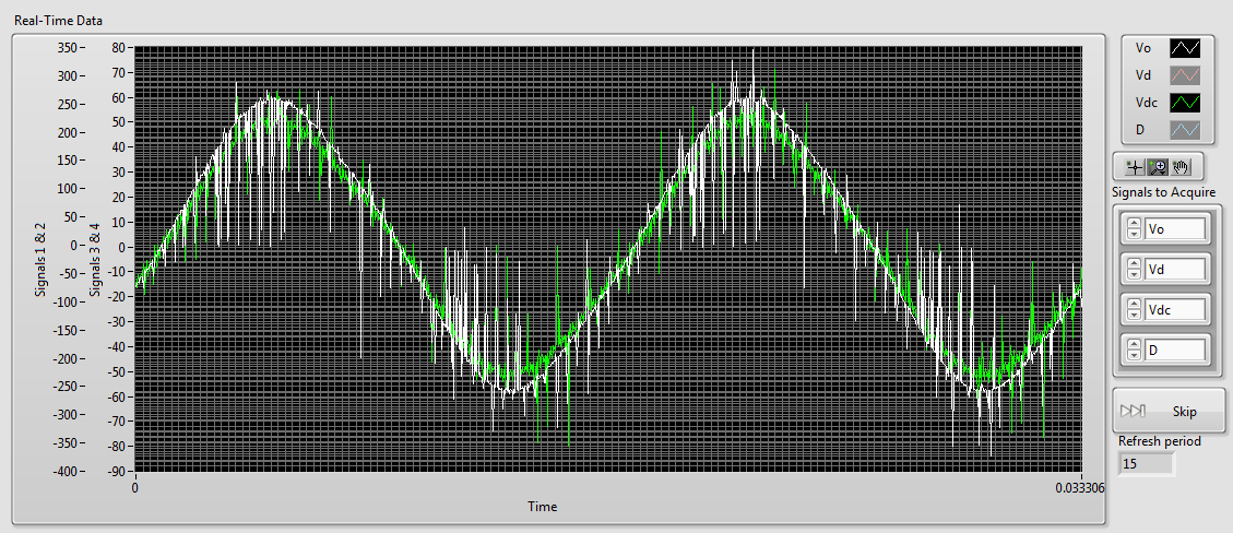
As you can see there is a lot of noise in the B sensor while sensor A is most often silent. When I connect then both of these signals to my NI 9215 I get the signals shown below (75 kHz sampling rate), sensor A appears in white and green B sensor (ignore the differences in scale, it's programmatically).
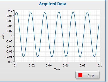
As you can see the noise level in the two now is comparably high. However if disconnect us the 9215 B, the signal from the probe sensor then replaces the image below:
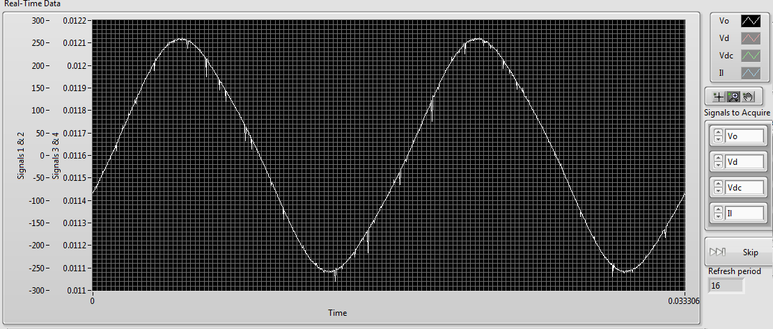
Although there are some present noise, the signal is much cleaner than before. The natural conclusion that I draw from this is that there is significant interference between the two signals. The same wiring is used for connecting to the 9215 as o-scope, and the two sensors use shielded twisted pair cables. This amount of crosstalk seems very high compared to the - 80dB listed in the specifications of the 9215. Any ideas what could be the cause, or how to fix it? Unfortunately, I am currently unable to afford a second sensor A.
1. by the impulses of the runt, I was meaning extremely short pulses on A sensor. If they are short enough, you will not see them unless you are looking for.
2. my concern is whether the switching noise is contaminant entering your power supply through the electric wiring. Of course, good feeds should filter this point, but it's just another thing to check.
3. the quick and dirty way would be to use a BNC T-connector to connect the oscilloscope and the ground in this way.
Suggestion of ferrite chokes on instrumentation Henrik is a good.
I understand that this type of inverter using the load (normally three-phase current motor alternative) to filter the frequency of bridge (10 kHz in your case) to the required frequency (normally 50 - 60 Hz). This means that high frequency currents go all the way to the motor, if they are not filtered by the cables first. You can not just screen the housing of the inverter, because the currents of high frequency down to load part of its operation. If you start testing things, you will all the way from the inverter to the load of the screen and will be impossible to Rodez to meet your instrumentation.
Standard WARNING: If you are tempted to connect directly to the UPS output and reduce until the input voltage range 9215: first of all, make sure that a qualified person has verified your wiring. Second place of fuses in all lines near where the tension is taken offshore. A UPS maybe a current loophole in the beach A 100 and you don't want that to the bottom of your wiring of instrumentation. Not directly relevant to your ad, but I feel that I specify.
Tags: NI Hardware
Similar Questions
-
I try to measure the AC current measuring brownout on a resistance. Using a NI 9215 signal looks like this and is not accurate.
When I plug the same signal to a USB not cheap-o 6008 signal seems fine and I am able the same voltage of RMS of my multimeter.
I would prefer the sampling frequency higher the 9215 since we are looking for distortions of the AC signal. What I'm missing here? Thanks in advance.
Hello
Both modules are connected in differential mode?
With NI 9215 - always shall be connected to COM (with resistance 1MOhm DIFF or directly to the CSR) because it is an isolated module (see fact sheet).
USB-6008 has no isoloation, but still need to bias resitors connected between IA a COM.
Maybe it's the cause of what you see.
Best regards
Matej Zorko
-
I can taste different channels at different rates in a task?
I use a NI 9203 modules and 9215 9211 in a single CompactDAQ chassis. The software is LabVIEW 8.6.
My VI use DAQ Assistant to sample all three modules within a single While loop. I can run the whole loop until about 13 kech. / S without problem. However, about 14 kech. / s, I get the following error:
"Error 200361 occurred at DAQmx Read (analog 1-d Wfm NChan NSamp) .vi:3
Possible reasons:
Measurements: Overflow of on-board memory. Due to the limitations of system and/or the bandwidth of the bus, the driver could not read data of the device enough fast to follow the flow of the unit.
Reduce the sampling frequency, or reduce the number of programs that your computer runs at the same time. »
I need to sample the 9215 signals up to 20 kech. / s, but the signals emitted by the 9203 & 9211 don't need that you can enjoy at the s/s 1. could reduce the sampling rate in the 9203 & 9211 signals solve my problem? If so, how to apply these different sampling frequencies high within the same DAQ Assistant VI?
-
Hello
I have a problem with the NI 9215 module, I use Ni9215 with NOR-ISB-9162, systems of six measures and the release of nor are in the enclosure. I have the signal distortion when I tried to measure the signal of a phase of the system 3 phases and do not have this strain when trying to measure simultaneously two or three phases. Another problem is when I tried to measure simultaneously both signals from different voltage dividers - I have terrible strain (scheme_6).
Might well want to explain to me, why I have this distortion of the signal on OR output.
I hope for your help.
Thanks for all answers, there is no problem in NI9215, the problem was high-potential on the 'ground '. That caused measures identified. So be careful with potential in your field and the common PIN of the NI9215.
-
The NI 9215 input signal voltage
Hi all
I tried to test NI 9215 BNC in MAX. And the acquisition of data took place without input signal.
The voltage for all 4 channels, I read is about 10.4 Volt.
Is this fair? I thought, the voltage should be 0 without input signal.
Best regards
GL
If you leave the open entry, it will tend to float to one of the rails. From my experience, it's almost always the top, so the 10.4 volts.
If you short-circuit the input, you'll get certainly 0 volt. You will probably get 0 or nearby yew, you put a resistance across the entrance.
-
Re: 46TL968 crosstalk / ghosting
Hi guys! Had some problems of crosstalk/ghosting with my Toshiba TV in 3D SDS.
When my PC is the source of movies, I get crosstalk that annoyes me. Overscan on my PC is at 0%, my TV uses the crop "native" method and the photo mode is "PC."The strange thing is, when you use a USB device and don't play movies from this source, there is no cross-all discussion!
Don't know where is the problem, the side of the PC, everything should be good.Summary just for your question:
The effect of persistence, but also vertical lines appears only if you connect the PC to the TV and only if 3D is enabled.
These problems don't appear if you use the s Toshiba TV internal drive (using USB flash memory key) or if you connect another device (PS3).Is this correct?
A number of questions:
Have you tested different HDMI ports?
The TV supports 4 HDMI ports. I recommend you all.Have you checked the display resolution and Hz settings for external monitor in the settings of your computer?
I highly recommend doing that. Manual page 91 provides details on PC signals supported through the entrance to the PC!The PC input on this TV only accepts signal formats that are compatible with VESA DMT.
Some input signals PCs is different from the resolution and described the frequency and so the phenomenon as incorrect display, detection of fake format, picture position down, blur, or jerks can occur.Another fact:
The TV automatically switches to 3D mode when 3D signal is detected.
Check the TV s auto start mode (this mode control that makes the TV, when it detects a 3D signal for more details user manual page 28-32) otherwise, you can change the display mode by using the 3D button.Finally, the format of the 3D signal can be together by side by side (SBS) or mode up and down (TB).
You will need to choose the right format if the TV can not it automatically detects see switching display mode or by selecting the 3D format.
http://www.Toshiba-OM.NET/LCD/PDF/English/Country_Specific/TL968-4046-English-specific.PDFWhen it is not getting signal from 3D format, display mode is not passed to 3D and if the format and the appropriate mode are not selected, 3D image is not displayed correctly.
-
Crosstalk channel PFI, error Code:-201314
Hello world
I would like to make several synchronized outer edge count the spots on a NI PCIe-6353.
The problem is that I get crosstalk of impulses between the channels of the PFI, leading to some sample clock pulses and possibly error-201314 misinterpreted:
"Multiple sampling clock pulses have been detected in a period of the input signal. Use a sample clock rate that is slower than the input signal. If you use an external sample clock, ensure that this clock signal is specifications voltage level and jitter and seedless. »
I count the pulses of the APDs, they have a height of 5 v, width 20ns and a rate of about 1 MHz. My sync Signal has a frequency of 10 kHz repetition, the pulses are 5V high and long 50µs. When I start the measure, it takes only a few seconds until the mentioned error is displayed. I can also confirm it with the NOT-MAX, in "cash" pulses in my sample clock input channel even if there is nothing in annex (only the DPA on the meter channel).
I tried the following combinations:
connected to sample clock: 0, 5 PFI, PFI 1 PFI
counter connected to: PFI0, 5 PFI PFI 8, PFI 3
they all failed except when I use the PFI8 as the only source of meter.
In addition, the edges of pulse with a lowpass filter of depreciation or the addition of a resistance of 50 Ohms for the connector does not work.
The connecting cable to the junction box is 0.5 m long. I tried the SCB-68 has and a BNC-2110 case without much change in behavior.
Is there a way to better isolate the PFI channels, or are there channels which are better insulated from each other?
Thanks for the help
Fabian
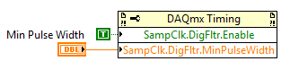
You can set up a digital filter on the sample line PFI clock to prevent noise to register as legitimate a sample synchronization signal (pulse Min set to something less than the width of sample clock but greater than the width of the pulse noise - 5.12 we we use built-in dividers and would probably be appropriate).
If you want to troubleshoot the source of the noise itself, I would start with the scope of the sample clock line (the scope must be fast enough to pick up the pulses of 20 ~ ns if it is indeed the source of the noise). I guess that the problem is more likely to how signals are connected/set to land. Do not forget that the PFI lines on the DAQ card share a digital ground.
Best regards
-
NIDAQmxBase uses differential signals?
I recently updated the NIDAQmx Base to the plus version and. But now I'm a horrible corruption of my signals. I checked with a scope and the signals are correct, but it sounds horrible crosstalk between channels. The only thing I can think is that the Council does not truly differential switching beyond the first 8 channels.
I use a card of 64 channels so there are 32 differential channels, I'm only using 16 channels beginning. I use ' Dev1 / ai0:7, Dev1 / ai16:23 "for the specification of my channel. The equipment works as the default "Datalogger" shows the correct data. But I'm guessing that the data recorder was built with an earlier version of the basis of NIDAQmx. This seems to happen when you use more than the first 8 channels. This VI allows to work with the previous version of NIDAQmx base.
Is this a known issue?
Here's the code to initialize the jury NOR-6033

Mac OS X 10.4.11 PPC / LV 8.5.1 / NIDAQmx Base 3.2.0 / VISA 4.4.0
Hi Scott-
I agree that relocation is the most appropriate next step. I tried here with a very similar setup and I could get the correct number of samples during my reading, and accurate data looked. Please let us know your results once the reinstallation completed. Thank you-
Ed
-
Digital output crosstalk PCI-6115
I am trying to create 8-bit specified output signals by various software-created the waveforms that are repeated indefinitely. A typical example of this waveform is a sine wave of 280 Hz. The configuration is as follows: (1) Ctr0InternalOutput used as the clock source. (2) clock frequency is 50 kHz. (3) the connections established with the connection of the terminal of the wire SCB-68 box.
I use an oscilloscope Tek MSO 4104 to 1 GHz (4 analog inputs, 16 DIO - 8 inputs are used) to monitor the digital signals of the 6115, either with analogue or digital scope entries. I was able to generate signals, but the problem I see is a systematic corruption of levels individual bit by other bits. For example, the MSB (that changes less often) shows HI-LO or LO-HI transient when you use the input OID field. With analog inputs range, this is demonstrated by spikes of noise of low-amplitude on the line given. All these transients are synchronous with the edges of the transition from other signals.
My guess is that it is some kind of problem termination or loop Earth with DIO 6115 connections. I first tried using a simple tablecloth (main 8 more on the ground) cable. I got some improvement by replacing it with the individual lines of 50 ohm RG-174/U, linking each coaxial cable to the digital earth nearest ground terminal. Then I put at the end of the output of each line of coaxial cable with 100kOhm and 100pF (parallel) to his shield to the ground. These measures improved the signals, but do not eliminate the problem. I'm looking for advice on how best to configure the connections of DIO or condition the signals.
I found myself in the land of P0, P6 and P7. This reduces crosstalk to acceptable levels. I do not pretend this is a unique solution, but the grounded all the shields of coax has not produced as net results. I found online OR hard to find, and inadequate documentation to discuss these issues.
-
USB-6211: analog input signal affecting another of the same map AI
Hello
I use the DAQ-nor-6211 map and DAQmx features to read a hammer and a signal of the accelerometer and then use other LabView functions to make the FFT of these analog input signals. However, it seems that the analog inputs where the hammer and the accelerometer are connected generate a kind of noise or influence in other entries of this data that is not connected to any other sensor acquisition board.
I've had different experiences in order to check if the problem is with reading the card: put the accelerometer and hit the dog in another table where the DAQ card table was located (to avoid the vibrations on the map and a possible noise), ai1 entry was logged on the differential mode on the dog and the ai4 of entry is connected to the output (z axis) of the accelerometer. The other 2 ai2 and ai3, entries that can also be read by my LabView program, are open (i. e., any other sensor is connected to the card). When the structure where the accelerometer is located is struck by the hammer, the signal of ai2 ("x axis" seen in the first attached document) has a curve (on the time domain) which initialize almost at the same time that the hammer and the a3 of entry has a weak signal, but with the swing as well as the signal of ai4. The document "hammer ai1 + z_axis connected_ _x_axis disconnected ai2 + y_axis ai3 ai4" images that I captured the chart created in LabView. On these graphs, it is possible to check on the FFT the ai3 signal and ai4 has the same behavior (with different intensities), and enlarged figure of time domain image, we can see that the signal of ai2 increase almost at the same time of the signal of the hammer (ai1). The signal picked up by the sensors are probably creating a sort of noise on open entries ai2 and ai3.
Another experiment was conducted to check if the signal from a single entry that may affect the signal read from each other near the entrances: the DAQmx task Create channel had a physical channel has changed: ai3 entry has been modified by ai7 (maintain the same connection mode: differential), and the results are visible on the second attached document. In the graphs obtained in this experiment, it seems that the entrance of the hammer (ai1) affects the signal of input ai2 and ai7, which are not connected. And the ai4 signal does not seem to influence the other inputs, because he has a different curve on the graph of the FFT.
The same experiment was conducted using the CSR connection (change threads and create the DAQmx Channel Configuration), but the results were the same as those found using differential connection.
Finally, if the output of the accelerometer is connected on the ai2, the signal of the other open entries ai4 and ai7 seem to be affected by the signal of the accelerometer on ai2 (last document attached).
Could you tell me if the problem I encounter is caused by the DAQ card with this information that I gave to you? And if the answer is Yes, do you know if there is a way to avoid this noise create in one entry on the other hand, it please?
Thank you
Maybe Ghosting or crosstalk? Just an idea.
-
small pressure with NI 9215 readings
I use currently the cDAQ 9172 map with several modules of inputs/outputs, analog and digital data acquisition. I'm trying to use the 9215 analog input module to measure voltages by a single anemometer. The playback for the anemometer range is 0-1 V. However, for our use, we analyze the low speeds giving no more than 0.2 V.
When the anemometer is attached to the 9215 module it will not register any voltage read unless it has a very high speed (and thus a higher voltage reading). We tested the anemometer with a simple oscilloscope and it records easily tensions low low flow rates, so the problem is not with the anemometer himself.
So these are my questions:
Is it possible that the 9215 is not sensitive enough for the< 0.2="" v="">
There also the problem that the cDAQ-9172 also contains 6 other modules e/s and is housed in a Cabinet and the signal is lost in the noise/interference?
Can I try in LabView itself in order to increase the sensitivity?
A big thank you to all those who can get an idea.
Problem solved!
Apparently, he was the son after all. I don't know what was the problem, but it is fixed and all right.
Thanks to everyone for their suggestions and help!
-
NEITHER 9215 delay in phase between two channels
Hello
I use Ni9215 with ENET-9163 to measure the phase between two sinusoidal incremental signals delay. First signal connected to AI0 and, secondly, to AI4 at 100 k sample rate. I know 9215 simultaneous ADC, but it seems to me that NI 9215 gives additional time between the channels. Is it possible, or l mistaken?Alexandr.
Hi Alexander,.
Please let us know how you get on,
Chris is correct - with the idea of using a right signal to both channels, I tried to suggest this earlier...
I hope this helps with your problems with delays,
-
Multifrequency 9223 9215 sync and 9213 in cdaq 9188
Hello
I'm trying to synchronize three different modules (NI 9223 and NI 9215 NI9213) every acquisition given to various higher sampling frequencies (e.g. 9223 = 1000 hz, 9215 = 100 Hz and 9215 = 2 hz) and write files to separate data for my task. I am using a cDAQ-9188 ethernet and all modules are in the same chassis. There is an external trigger (which comes from an external source) to start acquiring data which are wired connected to the PFI0 channel in the chassis. What I want to do is: whenever the trigger is high, acquire 10seconds of data according to different sampling frequencies high above and write in separate data files. I followed the procedure referred to in the http://www.ni.com/tutorial/5376/en/
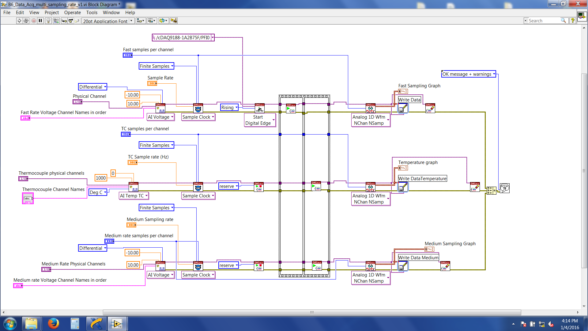
Here's a snapshot of the block diagram
Now, the problem I am facing is the 'average frequency (NI 9215) data' and 'data of Thermocouple (NI 9213)' are acquired and written immediately after that I have start the labview program. Fast speed data (NI 9223) are not written, and wait for the trigger signal. And then it throws an error 200284. If I do just a finished sample rate on NI 9223 alone (without adding/attempt at sync with other modules) with expectation of release it works without any problem.
LabVIEW files are attached.
Suggestions very much appreciated and you wish all happy new year.
Thank you
Roy
Hi Roy,
'average frequency data (NI 9215)' and '(NI 9213) Thermocouple data' is acquired and written immediately after that I have start the labview program.
Yes.
You forgot to set a trigger to start these DAQmx tasks!
And then it throws an error 200284.
The description of the error says something like "use a higher timeout value. Have you tried that?
-
Syncronize to acquisition of data with the generation of signals
Hello everyone,
My request is generate pulses on the output of two different to drive two LEDs and acquire detected pulse signal amplified photodiode.
Actually pulses are generated by starting the writing on the analog output, and then start the acquisition (I need 200ms on average), stop the acquisition, turn off the driving LED and develop the acquisition and record the results.
All this in a cycle it takes about 1.5 seconds to run.
Next step would be to drive the outputs with a waveform (duty cycle of 50% of width of 250 ms) and acquire the signal of the photodiode in synchronization with the edge of the pulse.
I tried to use the trigger function, but the examples are not clear on how to do it.
I use NI 9205 or 9215 to acquire signals.
Is there a particular entry to be used as a trigger?
Thank you very much for your attention
Hello
I found that NI 9205 has inputto that one be used as trigger signal, i.e. AI0.
At latest
Eugenio
-
Hello
I am a new mechanical engineer on FPGA and LabVIEW Real-time. I was trying to connect a sensor accelerometer for the NI 9215 Module of the 'C' series in the controller chassis 9024 cRIO but lives a hard time to find the right connections, especially with the 'GROUND '. I would appreciate a lot any effort giving me more insight on the problem that I am known and help me acquire a voltage signal. I went through various white papers, but none of them explained in detail.
Hi KarthikSrinva,
What you have described might work, but don't forget that the 9215 has a maximum range of +/-10V of its own reference to the ground (COM).
Because the battery is a floating (unreferenced) voltage source, you'll want to fill them HAVE - COM (common ground) terminals and to ensure that you have a common reference and the differential signal is not float out of reach of data acquisition. What is described in Chapter 3 of the guide to wiring field and noise considerations I think you were talking about earlier:
Wiring and considerations of noise for analog signals
http://www.NI.com/white-paper/3344/en/#toc3
Kind regards
Maybe you are looking for
-
Some of the messages I'm getting seem to appear randomly in my drafts folder - how can I stop this?
I used save as draft before, but now the messages seem to just randomly appear in the folder. At the same time, I got 200 messages 'project', messages, I had already sent. It takes a kind of problem of "timer", that is, if I leave the PC for a while
-
final cut stop recognizing my external hard drive when updating to yosemite
I have a mac book pro, and I work a lot in the final cut, 6 months ago I bought an external hard drive (WD 4to) just to keep all the projects, events and original media in here, but came to yosemite... I had to update to yosemite for many reasons, th
-
kb2453332 isn't day followed directive forum, regularly used fix it at least 3 times, then used aggressive correct it, then msconfig, services for the disabled, began to date still not, what then?
-
How do you stop memory waiting in windows 7
Windows 7 does not use memory standby when it is necessary so I would stop it. I have 8 GB of Ram, I play a game like Age of Empires 2 (I've played others with nothing else installed) and it stutters because eve has all the Ram and don't release it,
-
HP laserjet1020 more do not print
Please help laserjet printer does not print do not all