CV 1457RT and VBAI: Double digital output
I have a problem with the CVS 1457RT and the VBAI.
I configured two steps with the VBAI for the CVS.
The first step: I've read about the digital input which should trigger my second step.
the second step: I acquire an image (with an ACE of the Basler) and then I measured 8 distances and count 2 edges. After this, I generate a pulse on the digital output once.
After that I did a VI in LabVIEW that measures the time between the IO.
In this VI and on the module which is connected to the digital output, I see that the putput pulses twice but only a few times.
I guess you get noise on your digital input and trigger twice, so that it works the inspection twice, giving you two pulse output.
You can implement a digital filter, where the value that comes out of the filter does not change until entry remained at the same value for the N samples.
Bruce
Tags: NI Hardware
Similar Questions
-
More and more common digital output on USB-6001 with ULN2003A
I am ordering an engine step by step and the current required on the digital inputs of the stepper driver is close to 11mA (at 5V). My USB-6001 is not capable of producing this high current. I've seen people using the ULN2003A to control relay and it looks like it should work for my application. It will work and then I use the 5V output to go to the ULN2003A because it can produce for a 150mA. To associate the ULN2003A I use the 5V output and put the positive on the COM?
As you drew it should be fine. Do not connect data acquisition + 5 V because the controller inputs are opto-isolated. That circuit is also compatible with the 11 current requirement my mentioned in your first post.
USB-6001 digital lines are software timed so your maximum stage rates will be very high.
Lynn
-
Control the Boolean commands and generate a corresponding digital output
Hi all
I'm working on a project of activation of the electrode, here, I thought that how could I order an electrode in a time and generate a digital output of it accordingly. I want to replace it with each electrode with a LED on the front panel and generate a numerical value to each LED on the block diagram.
If it can be divided into two parts
1 control the Boolean outputs
Here, my goal is that if I have 5 leds that are used as a Boolean control, must be ordered so that only one of them lights up at the same time and the rest goes off.
I mean for example if #3 was turned on and that the user pressed the #3 #2 should be turned off and only #2 lights.
2. generate the corresponding numerical value
Depending on the position of the LEDs I want to generate a corresponding numerical value, as previously released 3 coming and exit 2 then comes when the second LED illuminates.I ask all participants to this group to help me with this.
Concerning
Why don't you use the radio button control? You can replace the boxes if you want the buttons.
-
USB 6008 digital output signal
I am VERY new to LabView and have been racking my brain trying to get digital output of my USB-6008. All I want is to be able to get a signal of + 5 V of my digital output when I click on a button. This signal opens a valve on a system I see so when it is pressed, it must stay open until I press the new button. It seems simple enough to me, but I'm not too familiar with LabView. Help, please!
Stripling07
You must first take the LabVIEW tutorials and then look at the links to get started with DAQmx .
The simplest program would be with the DAQ Assistant. Drop it on your schema, and then select digital output > digital line. Select the line when the wizard has completed, click OK. Wire a Boolean value in a table to build and the output of which is connected to the data entry. That's all. You can test the output of MAX (Measurement & Automation Explorer) with the test Panel. Do NOT test with your connected tap. Your valve may require more current that can provide the 6008.

-
Pull-up external USB-6009. digital output (open collector) allows onboard external + 2.5 V output?
Pull-up external USB-6009. digital output (open collector) allows onboard external + 2.5 V output?
Hello
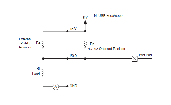
I want to config output digital USB-6009 to + 2.5 V above and 0 V digital output low. I know I can config USB-6009 digital output open collector with resistance to pull-up external, that can be applied with + 2.5 V power source.
My question is: can I use USB-6009 Board + 2.5 V output as the current source of resistance to pull-up? What resistance is a good number for the resistance to pull-up, if I can use this configuration?
Thank you much for the help.
Cathy
Hi Cathy,.
The digital USB 6008 front-end server looks like this:
So, there is actually an internal pullup to 5V 4.7 kOhm resistance when the device is configured to open collector.
If you want to display 0 to 2.5 V, I would look in a resistance of polarization of 4.7 kOhm between c and ground (according to the rest of your tour).
Best regards
-
Synchronization of analog and digital output with the external sample clock
Hello
First of all sorry for my English, I will try to explain what I want to do.
I want my PCIe-6321 to send two custom signals (modification sawtooths) on a mirror controller. I would also like to generate output with my card at the beginning of each tooth of saw. Everything must be synchronized with an external k-clock signal of 100 kHz. The idea is that whenever the PCI receives a trigger to external clock, it sends two analog output voltages and when he received 1024 clock ticks it will also send a pic of triggering TTL. What I do is first prepare the map and after that in a loop sending and modifing the output values of the two signals and at the same time send a digital signal Boolean in each arch, so when's done it 1024 iterations of the loop I send an event to the digital port. Attached you can see.
The problem is that I don't know how to synchronize both. Can I use the sample clock just to the analog output? I can use sample for the two outputs clock, or do I need to use the output of the meter? If don't know how to use it here.
If I do nothing else bad/wrong, I would be grateful for feedback.
Thanks in advance,
PabloI don't know how but I find the solution. I'm generating more than a positive value (as I was triggered maybe very fast the oscilloscope has been absent there). If I put the sample clock of digital output to use the sampling/ao/Dev1 clock that it doesn't, but if I put to use the same source as the OD (terminal where my external clock is connected), but the trigger to start the DO to be Dev1/ao/StartTrigger this works. I don't really know why, but it does.
Thank you for your patience and your help. I put here the final code.
-
Hallo,
I use the following system:
- OR PXI-1044 with controller NI PXI-8109
- OR PXI-2564 switch module to turn on the monitor of my test device
- Data acquisition multifunction NI PXI-6259 to measure the signal that responded to the questionnaire jump
The two cards are the same - PXI trigger bus. For both, PXI-2564 and PXI-6259 I use DAQmx to set the reading and writing of the channels.
Now, I want to measure the time between the digital output, my unit turns and the analog input, which measures the response of my system.
I can't do work by myself, please help me!
I thank Ludwig.
Hi Ludwig,.
If you can't give us any VI we have difficulties with to help you.
Because I Donat knowledge how your program is mounted it is not easy to know where you should enter signals.
Here's a question similar to yours:
http://forums.NI.com/T5/LabVIEW/best-way-to-measure-time/TD-p/178704
and 2 external links:
http://www.ehow.com/how_8698983_measure-time-LabVIEW.html
http://objectmix.com/LabVIEW/385152-how-can-i-use-LabVIEW-measure-time-between-analog-pulses.html
-
How to quit smoking all the void s vi before resetting digital outputs and then closing
I have a project that contains a main VI called home screen that calls many different sub vi. I am monitoring for a press of physical button by a digital input with a DAQ Assistant on the main VI and in this case I want my program to abandon all of its VI running and reset all the digital outputs before the closure of Labview. No idea how I would go all this?
I have attatched the basic model of what I do.
Joelspider33 wrote:
The problem is more to do with some of my money that VI running a DAQ Assistant using the same digital lines like the ones I'm wanting to reset and causing it to throw up an error message.
This is why you must set the DIO AFTER all subVIs are arrested. And to do this, you must send messages to these subVIs telling them to stop. If done correctly, it is a very quick process.
-
Fortunately the cRIO merger two time real screws: analog and digital output
Howdy,
I need help with a cRIO code. The purpose of the code is to acquire an analog input from the NI 9234 c series module and be able to send a "signal of pulse" digital camera (first low for some time, t1, then high for some time, t2) from a NI9401. Separately, I wrote the code to perform both tasks. However, when I add the code of RT digital output pulse pulses to analog input RT code, the DMA FIFO overflows because of the way that my digital pulse output code works. Currently, there are two reasons which overflows of the FIFO:
- The digital output code is pending for a while loop (pending "Send Pulse" become a true), the loop I can't empty the buffer FIFO
- The FIFO is not enough, quickly emptied depending on how long the pulse (t1 and t2) times are. The way I keep the pin high or low for a defined period of time is by issuing a sleep command, which blocks the loop I empty the FIFO. (Is there a "best" way to sleep?)
I have attached photos of my codes FPGA and RT. Please give me a suggestion on how to marry my two loops of RT for the use of happy resources! Thank you.
I found a quick way to solve this problem. I moved the timing of the Digital pulse on the FPGA. So whenever I have a Boolean value, the FPGA generates a waveform with the settings I put (a pulse in my case). This works because the FPGA loops run in parallel, I think. That's why, when I run a pending order in the loop of FPGA digital output, it does not prevent the FPGA of analog input loop to run. I have attached a picture of the code.
-
Speakers and digital output device problem
So yesterday, I installed a new video card. A Nvidia Geforce GT220. After installing it I noticed that my speakers were not working. The default program I used was Realtek High Definition Audio. I checked in Device Manager and noticed that the Realtek HD Audio Driver/program had a small yellow triangle with an exclamation point and that there are 4 new options named Nvidia High Definition Audio. Whenever I tried to run Realtek it says that the program has been installed, but may not be installed correctly. He said it was a Code 10. So finally, I deleted Realtek but the Nvidia High Definition audio drivers did not work. So, I deleted the drivers from Nvidia High Definition audio and tried to reinstall Realtek. My computer says that I installed it but there is no program to access my different options.
Now when I check the sound folder, during playback it says peripheral digital output (HDMI) 4 times.
Although the sound does not work.
Im just trying to run her on my Logitech X 540 speakers. When I plug the speakers that they appear not yet as an option in the sound folder.I don't really know what I can do to make it work.
I have a HP with Windows Vista 32 bit a1730n.
Hello TheInnocentMan,
You can try the methods below to resolve this issue.
Method 1:
I suggest you follow the link below and run the fix. This will automatically diagnose and repair problems with sound and audio on your computer. Here is a link you can follow:
http://Windows.Microsoft.com/en-us/Windows-Vista/tips-for-fixing-common-sound-problems
Method 2:
Check whether the default playback device is activated and the default value. It must essentially be your Realtek audio device.
a. open peripheral Audio and sound themes by clicking the Start button, click Control Panel, hardware and sound, and then clicking sound.
b. click on the playback tab, click speakers and then click Properties.
c. Select the device as the default device.
Thank you
Irfan H, Engineer Support Microsoft Answers. Visit ourMicrosoft answers feedback Forum and let us know what you think. -
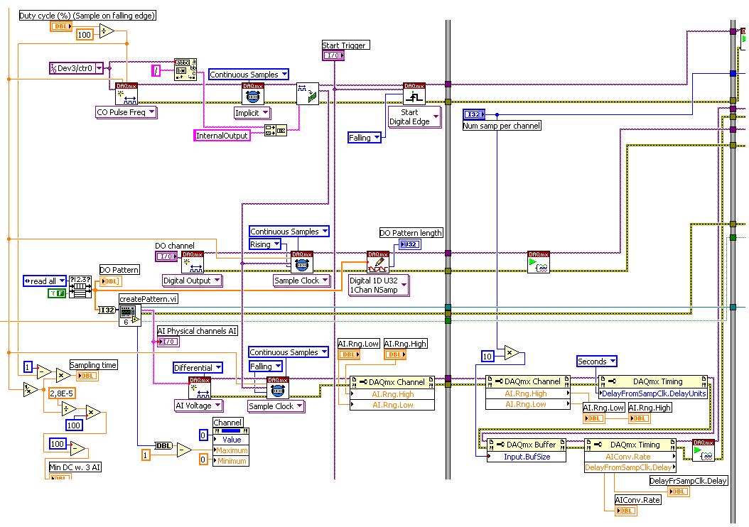
How to generate the digital output of the variable duty cycle and clock source being contrary?
I want to generate a digital pulse every front amount of my pulse counters. He must have a variable duty cycle. until now, I've been able to generate a digital output, but I can't change its duty cycle.
pls tell how I should proceed?
Thank you in advance...
-
Simultaneous analog inputs and one digital output (with NI6221M). Critical moment.
Hello!
Please excuse my bad English.
Idea:
I developed a device to measure the absorbance of light in the sample. The device will have 20 light emitting diodes (led) and 30 light sensitive photodiodes (DP). I have a PCI NI6221M card. As there are a lot of LEDS and PDs the device must use external multiplexing (MUX). The Assembly is shown in figure "DOAI System.JPG". "delta t" figure is not important. It may be zero, one or a few Americans. It is not essential for the operation of the device.
Opreation:
PD 1 will be multiplexed to the AI and the LEDs blinked (turned on and outside), one at a time. Then 2 PD will be multiplexed to the AI and again all LEDS flashing one at a time. The sequence continues with 3 PD, PD 4 and so on. Each blink a led should produce a sample of I. The sampling frequency of the AI should be about 12 kHz (so 80us for example).
Q: It will be possible to obtain from the Commission of NI6221M?
Problem:
I realize that there will be problems. When c generates an address on the MUXs there will be a delay until the LED driver, PD and input amplifier electronics of HAVE it settled. Q: Is it possible to delay the sample clock HAVE some 10 microseconds as to allow that to happen? (Perhaps use an internal counter operating on a basis of time much faster than 12 kHz sampling or use another for me still a feature is not known. May actually leave the sample clock HAVE be the 'master' and instead of delay clock.) Please see the "" calendar of GOT it. "" JPG ".
Q: Is it possible to control the time to settle for AI? That is to say that he can use the 6221, say, 30 US to settle before it reads the value. What these 30 arrive us before or after the flank of sample clock?All reviews are much appreciated,
Markus
Hello!
Just thought I should fill this thread by posting the code that we use now. The moment is as before, but we've added a few nodes property to coacha few parameters. In addition, 6221 has been replaced by a 6259Usb device that allows us to have the best insulation galvanic and more synchronized digital I/o lines.
-
separation of two edges using a digital output
I am using a DAQ, PXI-6229 map and programming in c# .net.
I'm claiming a falling edge on PFI12 used as a digital output, and I need to measure the time between this edge and a second front on PFI8 used as a digital input. I have implemented the code using some examples I found. I don't know when to to argue the signal on PFI12 in order to be read at the right time. Playback must be put in place before the signal is asserted, but I do not know how to set it up it up properly.
Here is the code I have so far:
Public Sub MeasureAcquisitionTime()
{
DigitalSingleInputTask = new Task();
CIChannel counterSetup;
firstEdge = CITwoEdgeSeparationFirstEdge.Falling;
secondEdge = CITwoEdgeSeparationSecondEdge.Rising;
Double minTime = 10-3;
Double maxTime = 60F-3;
String auxCounterInput = "/" + CardName + ' / PFI12 ';
String gateCounterInput = "/" + CardName + ' / PFI8 ';
counterSetup = DigitalSingleInputTask.CIChannels.CreateTwoEdgeSeparationChannel)
CardName + ' / ctr1 ', 'counter',
minTime,
maxTime,
firstEdge, secondEdge, CITwoEdgeSeparationUnits.Seconds);
counterSetup.TwoEdgeSeparationFirstTerminal = auxCounterInput;
counterSetup.TwoEdgeSeparationSecondTerminal = gateCounterInput;
DigitalSingleInputTask.Control (TaskAction.Verify);
runningDigitalTask = DigitalSingleInputTask;
counterInReader = new CounterReader (DigitalSingleInputTask.Stream);
Double data = counterInReader.ReadSingleSampleDouble ();
}I'm glad to hear it.
paofthree wrote:
Is there a way to make a measure of separation of two edges on the analog inputs of the PXI-6229?
The only way would be to constantly acquire the analog input voltage and calculate the separation of the two edges in the software.
Best regards
-
Manchester in transmission/reception of signals using the digital output of the PCI-6224
How a manchester signal can be sent and received using the OID of the pci card 6224?
I want to create a signal NRZ manchester on a digital output channel and then have the possibility to receive and interpret the same type of signal on a digital input channel.
Any help would be greatly appreciated.
Hi VJohnson,
You might find this post of discussion forum useful.
Looks like LabVIEW has not Manchester coding/decoding built, but do able in your VI by replacing all the elements with the corresponding elements of two and using double the speed of transmission as your clock frequency.
Thank you
Scott M.
-
audio output: optical digital output port (no sound!) macbook pro retina 15 mid 2015
My new recently Mbpr 15 inch has suddenly lost its sound, I went through the process of the toothpick etc but nothing. It worked perfectly fine earlier today, but I put in a mini jack into the headphone port and after to achieve 30 minutes later and taking the cable to THE that I had not his, then I had the red light coming out of the helmet but now its does not come in red and in the sound settings in system preferences its impasse on "optical digital output Port.
I now have to wait a week to wait until I can get seen at my apple store closet, I coming projects upward and in the middle of deadline and really using this Mbp to work, I literally only had a TI surly less than two months, I shouldn't have any problems. So if anyone knows anything I would appreciate it a lot! I need help to get this resolution as soon as possible! the last post I saw this was in 2006-2012 no new thread on this recently!
Thank you!
Jasonwaterz wrote:
I then had the red light coming out of the helmet but now its does not come in red and in the sound settings in system preferences its impasse on "optical digital output Port.
Try resetting the NVRAM/PRAM http://support.apple.com/kb/ht1379 memory
Maybe you are looking for
-
I want to commuicate one module profibus PXI, who is having a serial port. Is it possible to send and receive data through serial communication? If this is not the case, what are the additional factors need for communication?
-
Speedy Pc Pro, claimed Microsoft Partner
I have automatic Microsoft Updates and Security Essentials, most my Verizon email provider DOE is a free automatic security using the McAfee software scan. "" But a quick scan Pro of: software, system problems malware, performance issues, elements of
-
I want images in CMS format, but it only helps to px, how can do this, on the publishing server?
Hello I want images of size by bu cemtimeters it only lets px, how can do this, on the publishing server? Thank you Daisy Original title: size
-
The use van mijn HP Officejet printer 6500 E 710 a - f, problems ik ondervind puts the use of printer mijn computer, komt er vanaf dan steeds het pages next. Print spooler service local op Kan niet starten computer. DOING 1053: service has to start -
-
Update Adobe Reader XI 11.0.12 problem
For some reason when he tries to do the update it fails at about 80%. He can not find the installation package (C:\ProgramData\Adobe\Setup\{AC76BA86-7AD7-1033-7B44-AB0000000001}\AcroRead.msi). The package only I see in the folder adobe is ({AC76BA8