Cycle of use of digital inputs
I'm trying to use meters to measure the duty cycle of a digital camera so I looked at the ReadCtrFreqScalar function but I'm struggling to find what kind of channel must be created for this type of reading at work. I started to do a CIFreqChan and ReadCounterScalarF64 to measure this, but using the same channel to measure the duty cycle is giving an error indicating that the playback function does not match the type of channel. Can anyone help? I just need to know what channel creation function, I should replace the frequency with.
Note: Specifically, I use NEITHER cDAQ-9178 with the module OR-9421 (d - Sub) If this is useful.
DAQmxCreateCIPulseChanFreq
Do not use the two readings, only DAQmxReadCtrFreqScalar.
Best regards
Tags: NI Hardware
Similar Questions
-
How to use the digital inputs? (PCI-6010)
Hello
I have a PCI-6010 card and I tried to use a pulse generator in one of the channels of entry without success, I m using panels of 'Test' in MAX.
How can I configure dthe hardware to make it work?
Thank you
APOs instalar a ultima versão labview refazer tudo bem mouse conexoes as w.
Any forma, obrigado pela a definition.
-
Raising an event based on digital input? Treatment of a condition of emergency stop
I'm working on a test sequence into LabVIEW. I have a security which I am followed by a digital input the relay status, and I would like to pass to my failed state that I am in a State of emergency. (In my case, this happens when a barrier is broken or emergency push button is pressed).
It would be easy to do if I could use a digital input to trigger an event. However, this doesn't seem to be possible. I tried bind my digital input to a control, and then follow the State of the control as an event, but that doesn't seem to work.
My main problem is that I can be in one of the stages of test 5 seconds approximately. So far, I have not found a way to out or interrupt this step if my digital input changes state. I can get it to transition to the failed state after the step in progress, but I want that it to transition immediately when the safety relay is broken.
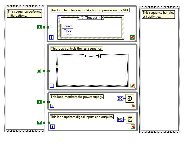
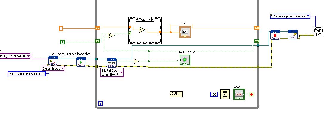
I've attached a picture that shows the basic structure of my program. The actual program is much more complicated, so I hope this is enough information to get started. I have stops in each loop attached together with the help of a subvi, which basically returns a Boolean TRUE if you press the 'stop' on the operator interface (it is one of the events of my structure of the event).
It seems that it would be a fairly common situation that there must be some answer I'm missing. Can anyone help? Thanks in advance...
You need (somewhere) a loop that monitors the digital status and can detect the transition Fail. The timing of this loop of 'surveillance' apply to how fast you can respond to failure.
But now you need to trigger an event when this happens. When I started programming in LabVIEW, I learned on the events of signs of value that could trigger programmatically a value indicator has changed. However, a few years later I learned the user events, a more flexible method for generation "software interrupts' who have a number of advantages over value of signage.
I don't know if you are looking for using LabVIEW or LabVIEW examples user events you'll find a good explanation for how to use these (use the Help Index, and then type user name).
Bob Schor
-
With the help of digital input for Boolean control?
Hello!
I have spent a lot of time to search but have not found a solution to this...
I have LV 2015 with chassis NI 9188 and module NI 9425 DI. Try to use the input signal to assign a State structure machine program and/or events in real time. It would be acceptable to have an indicator show the status of the input line, since I can use it elsewhere with Value (Signaling).
Please do not ask for the code - the problem is quite simple. I just want to use the digital inputs to program control as a T/F. I want just the program to analyze the State of the input and decisions - a bit like a PLC.
All I seem to be able to extract is data of digital waveforms with a task DAQmx.
It's not a trigger - I already use a trigger to start the analog acquisition.
Formulate the problem in a simpler way... What to do if you had a digital input module and you wanted to see the status of each input line in the form of a LED on your face in real time. How would you do it?
I really appreciate the help!
greyhorn23 wrote:
Formulate the problem in a simpler way... What to do if you had a digital input module and you wanted to see the status of each input line in the form of a LED on your face in real time. How would you do it?
I would like to write what has been read to the Terminal.
From what I can tell, you want to just read a single static value from your digital line. You can then simply read the value of one and do some logic with her.
-
Duty cycle of measurement using digital inputs DAQ
Hi all!
My system has a PXI-8269 card and I want to measure the duty cycle of the Digital PWM signal generated by a device.
To acquire this signal, I'll use a digital DAQ (PFIx) instead of a counter of data acquisition (CTRx) (they are already used for other applications).
The search of the database of examples, I found live who use meters. So I wonder if it is possible to do that and how could I.
Thank you!
Sorry, the correct reference is PXI-6289.
I was determined to acquire a digital waveform, converting it to an analog waveform and then using the correct function in the range of functions->-> Analog wave.
Thank you!
-
How can I measure the time between the two edges of successive increase, using digital input...
Hello
I'm trying to measure the time in seconds between each two successive rising edges on a digital input.
So far I managed to detect the rising edge, increment a counter at each rising edge and take the time during which the increase is edge
all I need now is subtract edge currently rising from the previous era of edge rising to calculate (T), which can be 1/frequency and display in real time for the user.
but I do not know how to do this

Can someone help me please!
Note: while I am in a position varies between 200 ms - 2 seconds
-
How can I measure the time between each two successive increase edges, using digital input?
Hello
I have tried two measure the time in seconds between each two successive rising edges on a digital input.
So far I managed to detect the rising edge, increment a counter at each rising edge and take the time during which the increase is edge
all I need now is subtract edge currently rising from the previous era of edge rising to calculate (T), which can be 1/frequency and display in real time for the user.
but I do not know how to do this
Can someone help me please!
Woah!

Sorry Apok, but your code becomes much too complicated and salty. I don't think that all records to offset or Boolean conversion/operators are necessary at all.
If you want to measure the time between two keys so it's another (much less complicated) way. It simply records the time when press button in a registry change, then compares the two.
-
Digital input to Toshiba 46TL-> no analog audio output to amplifier
Hi all
When I connect a video source (e.g. computer laptop via DLNA) to my 46TL, output TV audio analog (red/white taken connected to an amplifier) does not work.
It does, however, watching television.
Is it possible to configure the TV to read the audio data from digital input (HDMI/DLNA) to the analog output?
Thank you for the help
Not quite what series of TLxxx you have, but for example the TL938 supports a digital (optical) audio output port that provides a digital audio signal.
Why n t connect the amplifier to the TV using this Jack?Connectors for component video / audio to the rear of the TV are the ports of ENTRY and not the OUTPUT ports. So, you can send an audio signal to the TV and not the amplifier output.
-
Hello
I am relative new to LabWindows.
I have a program that starts when I press a button. The program controls a motor. Now I press a button on the motor and the program must cease (Safty Stop). The button is connected to a digital input on my card (PCI Express 6343). Now, I have the question, how do I program the interruption? I know not how do in CVI (controls the digital input whenever the program runs).
I hope someone can help me.
Best regards
The starting point must be to look relevant examples that NEITHER provide:
ReadDigChan - ChangeDetection.prj
and
ReadDigChan - ChangeDetectionEvent.prj
However, I must advice against using a PC as a "Safety Stop". As a general rule, the PC are completely inappropriate to the core functions of security, unless you follow the standard IEC 62304 relevent to the letter. Tip: it's hard to do with a PC. To implement safety functions such as emergency and interlocks stops you buy much better a specialist dedicated safety relay and following the instructions of the manufacturer. If life-threatening energy (either electric or medcanical) may be present, then consult a professional engineer.
-
How can I set up a digital input task to read continuous samples?
I am trying to create an exclusively digital task that will make digital readings at a rate timed by the material using a PCIe-6509. However, when I try to put the task timing as follows (which works on a PCIe-6509), I get the following error:
Requested value is not supported for this property value. The value of the property may be invalid because it is in conflict with another property.
Property: NationalInstruments.DAQmx.Timing.SampleTimingType
Required value: NationalInstruments.DAQmx.SampleTimingType.SampleClock
Possible values: NationalInstruments.DAQmx.SampleTimingType.OnDemand, NationalInstruments.DAQmx.SampleTimingType.ChangeDetection
Task name: DigitalInputTask
State code:-200077
The relevant parts of my code are:
public class DigitalInputReader: IDisposable
{
public DigitalInputReader()
{
dataReadyHandler = new System.AsyncCallback (DataReadyEventHandler);daqmxTask = new DigitalInputTask();
daqmxTask.Configure (Globals.NI);daqmxTask.Control (TaskAction.Verify);
daqmxTask.Control (TaskAction.Commit);daqmxReader = new DigitalMultiChannelReader (daqmxTask.Stream);
}public class DigitalInputTask: task
{public DigitalInputTask(): {base ("DigitalInputTask")}
public virtual void Configure (NiConfiguration niConfig)
{
<= niconfig.digitalinputs.count="" -="" 1;="">
{
String physicalChannelName = niConfig.Device + "/ port" + niConfig.DigitalInputs [i]. Port.ToString () + "/ line" + niConfig.DigitalInputs [i]. Channel.ToString ();
String nameToAssignToChannel = niConfig.DigitalInputs [i]. Name;DIChannel ch is this. DIChannels.CreateChannel (physicalChannelName, nameToAssignToChannel, ChannelLineGrouping.OneChannelForEachLine);
c. InvertLines = niConfig.DigitalInputs [i]. InvertLines;
}
var signalSource = "";
This. Timing.ConfigureSampleClock (signalSource, Globals.MachineSettings.SampleRate, SampleClockActiveEdge.Rising, SampleQuantityMode.ContinuousSamples);// Globals.MachineSettings.SamplesPerChannel);
}
}The last call to Task.Timing.ConfigureSampleClock, it's which throw errors.
Of the options available, or SampleTimingType.OnDemand or NationalInstruments.DAQmx.SampleTimingType.ChangeDetection provide the same precisely timed calls that I am familiar with the analog input interruptions.
How is it possible in a digital task? I mean, it seems that I could set up another task to do call by material for the production of a clock signal and use the ChangeDetection synchronization mode, but this seems a bit complicated for what should be easy to do. What Miss me?
Update: I thought about it. You cannot call ConfigureSampleClock when the digital input card is a device of 650 x, because these devices have any automated examples of clock. They are configured to run in mode default finite samples. You must make all sample synchronizing with these devices in the software.
Be cautious, however, because the .NET timers ensure they put any faster than their scheduled interval. In practice, they are usually 5 to 10 ms slow by tick. This means that if you want to read samples every 100 ms by sample clock, you'd end up reading all 108 ms samples. All counters based on the elapsed time and number of samples would be away after a few seconds of it.
Instead, you must do one of four things: write a doggone driver that runs in ring 0 and interfaces with the PCIe card in the required interval (i.e. on NC, not you, in practice), tolerate the inclination of the clock, use a multimedia timer as an interruption audio or video that is more likely to respond to the correct interval, or , my solution, an accurate clock allows you to set the interval of the timer. I wrote the following code to the timer:
var CorrectiveStopwatch = new System.Diagnostics.Stopwatch();

var CorrectedTimer = new System.Timers.Timer()

{
Interval = targetInterval,
AutoReset = true,
};
CorrectedTimer.Elapsed += (o, e) =>
{
var actualMilliseconds =;Adjust the next tick so that it's accurate
EG: Stopwatch says we're at 2015 ms, we should be at 2000 ms
2000 + 100 - 2015 = 85 and should trigger at the right time
var StopwatchCorrectedElapsedMilliseconds = newInterval +.
targetInterval-
CorrectiveStopwatch.ElapsedMilliseconds;If we're over 1 target interval too slow, trigger ASAP!
<=>
{
NvelIntervalle = 1;
}CorrectedTimer.Interval = NvelIntervalle;
StopwatchCorrectedElapsedMilliseconds += targetInterval;
};I hope this helps someone.
-
How to combine several digital inputs for playback?
Hi comrade Labview users.
I just started using LabView and I am very new to it. I know him understand how it works and you have something to work, but I need to be more effective.
I use DIO96H - USB DAQ Measurement Computing, which includes 96 digital inputs. I use the DAQ to acquire the activations of relay and record the number of times the relays flips.
Basically, I created a digital input read and then copy & pasted 95 times... it works but I know that's not the best way to use LabView.
How can I change the digital input (Di1/1stPortA/dev0) in multiples so that it iterates through all 96 channels without copying and pasting the same pattern over and over again?
Leon
You have the correct polymorphic instance for playback? Once again, for the material OR it would be a NChan Read. There should be a similar choice if I remember correctly.
-
Reduce the period of sampling of the digital inputs of NOR-USB-6009
Hello
I need to read a line of digital input in the NI USB-6009 using NOR Express 2013 Signal box. I selected 1 sample (upon request) as acquisition mode. I need to define a smaller sampling period as 1 MS, but it gives error too short sampling period: "the current sampling period is too short. Please specify a longer sampling period. ».
I do not understand the reason for it and a way to slove this.Any help would be greatly appreciated!
Thank you!!
The 6009 doesn't have a clock that you can set for a sampling period. According to the specifications, the digital I/o is software programmed - sample on request you use now. I'm not at all familiar with SignalExpress but I don't think that you can find near a reliable khz sampling frequency on Windows or any other os non-deterministic.
-
Hello
Is it possible to trigger action digital input using the signal I want to measure? In the example:
I want to measure PWM on P0.0 after first rising edge PWM on P0.0, but using only this line P0.0 (no PFI in use, only one used digital entry).
IM using X SERIES USB-6353.
Some DAQ cards can trigger on analog edge of the signal you want to measure. If a DI data extraction, it is possible to select only the PFI or similar as trigger. What is your application? What you want to achieve?
I can imagine you could workaround: record streaming samples of DI and do a SW trigger in your program, so you can get the same samples prédéclenchés (as in a digital oscilloscope).
-
Hello world
I use an NI USB-6501 and I'm trying to understand how to read the entries.
I used this card to generate output using the example vi write Chan digging, it works fine.
Now, I'm trying to use the example of reading dig Chan vi to read an input voltage. But it seems that, by default, the map reads 5V (a 1 logic) as entered on each pins, even if nothing is connected to them. I tried to connect the output to the input, use a relay to see if it detects a change in the entry, if we send a voltage or not, but it changed nothing. It still reads 5V anything.
Can someone help me understand how to be able to read an entry? This problem has happened to someone else?
Thanks in advance.
Frédéric
If you dig through the data sheet, you will see that there is a 4.7kOhm shoot all digital inputs. So with the floating inputs you will get a high (logic 1).
As Dennis have already said, wire your digital output directly into your digital input. So everything that you set the output that you will read on the entry. I don't know what you do with a relay.
-
6259 switch digital input to output
Hi all
I use the NI PXI-6259. One of the digital inputs I want to switch to digital output, send a serial code and switch again one digital input.
Does anyone have experience with this kind of configuration change during execution of the VI program.
Thank you
Basically delete the task that he had as an input, create another task DAQmx with channel configured as output, this task, erase it, create the task with channel configured as an input.
If you need a tight with switching schedule, I wouldn't recommend this Board. You may need to set up a Council of RIO with LabVIEW FPGA.
Maybe you are looking for
-
Toolbar of white smoke somehow got into my system, I can't remove it add or remove program
How does one get rid of an add-on unwanted, I have tried to launch Spybot and Ad-Aware and Add Remove programs and Norton, I still can not get rid of the white smoke with Mozilla
-
Access rights potential vulnerability EDB - 31617 Bad
Hello I received a warning after a network scan of Eset Internet Security tool. With this message 'potential vulnerability EDB - 31617 Bad access rights', do you know something about this vulnerability? This issue is already known for a different mod
-
How long does it take to restore a computer to factory default
I play a factory default restore... it is supported for half an hour... how long should it... something is wrong... .this which I do...
-
HP Slate 6, (problem: do not turn on the display, by pressing the power button once)
A month ago, I bought the HP slate 6. The screen does not light by pressing the single time power button. But if I press the power button three times, then it lights. I also make sure that the switch has no problem. I think it's a software problem no
-
T510 HP - do not click on Flash videos, they do load and display if
Hello The device in question is a version of the device T6X43202 t510 HP When it is connected to Citrix video flash will load and display correctly, but you can not click on them. It seems that the mouse downwards is not detected by the flash video.