DAQ 6008 4-20mA output
Oh wow, first post and don't even know if it really belongs here, but... in any case...
I am a beginner and I am a little lost.
Need to work on a final project and it seems that I do not understand how to turn it on. I need to use a lm35 (temperature sensor) as input to data acquisition and output... to this 4-20mA that controls the speed of an air/fan Extractor.
At 25 ° C the fan should stop, and gradually increse will get its speed depending on the temperature as in, at 40 ° C is max. And at 50 ° C, necessary of LED lights as a sign "emergency."
I know that I would need a few resistors in the... Range of 200-250 ohms or more, but... How to connect all this * beep * the output of data acquisition for the fan? because it's just a project I'll use one of these fans of pc/laptop as the "air Extractor.
Thank you, peace.
Tags: NI Hardware
Similar Questions
-
Hi all.
I work with an application that is count the pulses of an encoder hollow shaft renco to measure the distance traveled on a platform single axis powered by a ball screw and controlled by an engine step by step. The encoder is mounted at the opposite end of the motor directly to the ball screws.
That said encoder has 100 impulses per revolution and at the moment im using only 1 channel on its release to make the count. I use the channel of single window on a DAQ 6008 real counting down.
Here's my problem.
When I run the engine at a moderate speed and measure count pulses from a full trip on the axis I get 8200 impulses. If I reverse the engine now and bring it back at the same speed, the full trip will give the same 8200 impulses which is exactly what I want. However, if I run the motor at extremely slow speeds the same 8200 impulses correspond to only 3 quarters of the race on the same axis.
My hypothesis is that at top speed the DAQ 6008 lacks a large number of charges. I am correct in this assumption? I will soon have access to a DAQ 6211. This will provide a more reliable metering device?.
Thanks in advance guys. I'd appreciate comments.
It is just as likely (if not more) that you are picking up additional indictments at the slower speed - you can confirm enough easily by calculating how many pulses to be emitted during the movement of the platform to the desired distance.
The signal directly from a quadrature encoder can be quite noisy. The 6008 is only able to edge simple counting, so no noise on a front amount could lead on Board being counted more than once.
The 6211 supports a specific type of channel linear encoder, which configures the meter to use both signals A and B of the encoder. In this mode, the meter requires alternating the edges of A and B to continue incrementing, which means a noisy transition will always only picked up like an edge.
In case you do not have access to both A and B signals (or if the encoder is particularly noisy for some reason any and produced false edges in the middle of a period of high/low), the 6211 also supports filters PFI (link pdf Manual of use).
Best regards
-
Find the difference of pressure between the two transducers using a NI DAQ 6008
Hello
First of all, I'm a relatively inexperienced LabVIEW Developer, so my apologies in advance if this message does not have something, or otherwise lacks clarity.
I try to develop a VI as follows the pressure difference between the 2 EME 3100 pressure sensors (4-20 my), related to two different pressure lines, using a NO-DAQ 6008. I would like for the acquisition of data to read the two transducers, then have him find VI the differential and write this differential in an Excel file.
The data sheet for these sensors may be found at: http://www.gemssensors.com/Products/Pressure/Pressure-Tranducers/Sputtered-thin-film/~/media/GemsNA/... It is a 3-wire system, with a voltage between 8 - 24V. I use an external power supply of generic brand to power sensors, which provides a maximum of 24V @ 4A.
I drifted my physical connection (for the two transducers) this thread http://forums.ni.com/t5/LabVIEW/I-am-having-trouble-Omega-PX4200-Pressure-Transducers-to-where-I/m-p... and am relatively certain of the accuracy of the information. For purposes of signal conditioning, I use a 500 Ohm resistor between the signal of each transducer and the Earth wire. On the side of software, I use the latest version of LabVIEW (2011) as well as MAX on a Windows 7 64-bit machine.
In an ideal world, the sampling rate would be as high as possible, but 4 samples per second would suffice for all purposes useful.
Given this goal, are there any sample of VI (especially for MAX, which I have not yet used) who would be similar/applicable to this project, specifically, regarding setting a sampling frequency, calibration of the transducers or affecting the pins/channels appropriate? All resources would be greatly appreciated.
Kind regards
MG Wilkinson
Measure the voltage between the two resistance (resistance by probe 4-20 MA) using the differential inputs of the x 600.
When you configure the task, you can read several entries at once, by entering in "Dev_ / AI0:1" in the physical channels and using the "several channels / {unique |}". multiple} samples"polymorphic instance.
600 x can read 1kS/sec.
Do maths/conversions on the table, and then simply subtract the two tables.
Could also take some samples (10-100) at 1 kHz and their average together, give you a smaller rate effective sampling but with less noise.
A loop of producer-consumer would be good architecture here, let the daqmx reading live in a loop and sends the data via a queue to a 2nd consumer that performs mathematical operations and write to a file.

-
Continuous output signal using usb DAQ 6008 in matlab
Hi Takou,
You already post with the same subject. Is this the same thing, isn't?
If so, refer to the following link:
How to get out a sinus with usb 6008 on MATLAB
Best regards
-
DC motor of control using the analog output of DAQ 6008
Hello
Since the 6008 DAQ implements not good PWM, can I control the speed of the DC motor using outputs analog, protected by amplifiers?
This will damage my DAQ?
Ok. The engines will be quite low.
Consider using an LM317 as the "amplifier". Add one or two diodes protection. Connect the AO to the terminal of the regulator with a resistance setting to land. Your output voltage can go down to 1.25 V and up to minutes (battery-2 V, Vaomax-1,25 V). If you have a battery of 12 V and a 12 V, the maximum speed of the motor engine will be slightly lower than the nominal speed full. The minimum voltage the motor probably will not work. The regulator has a built in protection against overcurrent and overheating. It's the motor controller cheaper you can do and works very well.
If you need to reverse the engines, things get complicated a bit more. You can use a DPDT relay or a transistor H-bridge.
Lynn
-
I use the outgoing/incoming analog DDK with the DAQ 6341 SMU map.
The examples, for example aoex5, show a single timer (method outTimerHelper::loadUI), but the example shows the DMA loaded with same size of vector data.
There is a comment in the outTimerHelper:
 call rogramUpdateCount, which implies that memory sizes different pad per channel can be used.
(the comment is: switching between the sizes of the various buffers is not used)
Nobody knows what should be the format the DMA buffer for data from multiple channels with different frequencies?
For example, we want a0 with a sinusoid at 1 kHz and a1 with a sine wave of 1.5 Khz. What looks like the DMA buffer?
With the same frequency for each channel, the data are interleaved, for example (ao0 #0, ao1 #0; ao0 ao1 #1, #1,...), but when the frequencies for each channel is different, what the stamp looks like?
Hello Kenstern,
Data are always intertwined since each card has only a single timing for each subsystem engine.
To AO, you must specify the number of samples that will be released to the AO. You also specify the number of channels. Because he didn't is that a single engine timing for AO, each AO will be channel will be updated at the same time to update clock tick. Data will be interlaced exactly as shown in the example because each channel AO needs output at each tick of the clock to update. The data itself can change depending on the frequency you want to copy.
kenstern wrote:
For example, we want a0 with a sinusoid at 1 kHz and a1 with a sine wave of 1.5 Khz. What looks like the DMA buffer?
With the same frequency for each channel, the data are interleaved, for example (ao0 #0, ao1 #0; ao0 ao1 #1, #1,...), but when the frequencies for each channel is different, what the stamp looks like?
In your example, you must come with an update rate that works for the two waveforms (sine waves of 1 and 1.5 KHz). To get a good representation of a sine wave, you need to update more than 10 x faster than your fastest frequency... I would recommend x 100 if possible.
Update frequency: 150 KHz
Channels: 2
Then create you stamps that include complete cycles of each wave you want to produce based on the frequency of update. These buffers must also be of the same size.
Buffer 1: Contains data for the sine wave of 1 KHz, 300 points 2 cycles of sine wave
Buffer 2: Contains data for the sine wave of 1.5 KHz, 300 points, 3 cycles of sine wave
You can Interleave them as before. When the data are performed through the ADC, they are out different sine waves, even if the AO channels are updated at the same speed.
-
Hello
I have a problem during execution of a measure of voltage using 6008 DAQ board.
I need to reconnect to the Commission whenever I want to measure otherwise if I launch the program, stop and then run it again
I get error 200284 saying that some or all of the requested samples are not yet acquired.
Any suggestion is welcome.
Thanks, Chipet
Hey Chipet,.
I looked into this error code for a little bit and found this article that passes on a few common reasons to get:
http://digital.NI.com/public.nsf/allkb/FEF778AD990D5BD886256DD700770103
I don't know where this happens in your VI, but I guess it happens when shows you samples. Setting the type of reading you do (finished vs continuous and corresponding settings) could be useful. Here is another article that goes through some of the most common functions DAQmx and when to use:
http://www.NI.com/white-paper/2835/en
Hope this helps,
-KP
-
DAQ product with +/-analog output 12V?
We are looking to update a manual test area.
We are looking for a product DAQ with analog outputs capable of +/-12V
We are not generating waveforms. Just using LabVIEW to a tension he set in the range of - 12V and + 12V.
OR anything with this ability he selling?
I found the NI PCI-6703 and would serve our needs except that it is +/-10V.
Good morning New York,
Consider the SMU-4322 or NI 9269. The SMU-4322 supports + / 16V by channel. The NI 9269 has 4 (+/-10V) channels that can be cascaded for isolated older tensions.
Kind regards
Izzy O.
Product Support Engineer
NI.com/support
-
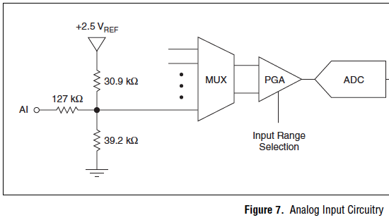
Issues of analog input DAQ-6008, voltage not zero to pin when you are offline
I use the 6008 NOR-DAQ to produce a series of tensions and then read a sense resistor using the analog input (CSR). I noticed that my analog input gives me 1.3 V, when I probe it (compared to the mass of the device), when it is completely disconnected. This changes the reading to give me a different measure of sense than expected resistance.
Why is my pin for analog input non-zero? Any help would be appreciated. Thank you!
The 1.3 V is expected. The USB-6008-and-6009 case have the strangest input of the world circuit. The input impedance is approximately 144000 ohms terminated in 1.4 V. check the document User Guide and specifications.
Lynn
-
I want to vary the speed of a 12v dc fan using a mosfet with a DAQ 6008.Is this possible.
I am a college project that is to use a data acquisition to monitor and control the temperature. I use a LM35 temperature sensor. I need to control the speed of the fan a12v dc. I use an external power supply of dc 12. I hope to control the fan speed by varying the voltage of 5v to the door of the
MOSFET. Is this possible.
Hi shaggydog.
You can use one of the channels of analog output of the USB-6008 output a variable voltage to the gate MOSFET, this should provide the features you need.
-
Integrate USB DAQ 6008 program Labview
I'm new to LabVIEW and am currently writing a vi to access the 6008. I'm using LabVIEW 2012. I installed the driver NOR-DAQmx 3.6, however, the sample code is code c - no vi. Also, I can't see examples of NOR-DAQmx in the finder of the example. I downloaded various examples, but each are missing Subvi which I believe should be installed with the driver. All advice is appreciated.
Harry,
1 DAQmx Base is only supported on Mac OS. You can find petitions on the exchange of idea ask for better support.
2 DAQmx and all its beautiful examples are not installed on the Mac. This means that the measurement and Automation Explorer (MAX) is not installed on the Mac and things such as the DAQ Assistant exist (although it is not a great loss).
3. when DAQmx Base is installed on Mac OS X with LV 2012 you should have the DAQmx Base screws accessible from the measures of e/s palette.
4 installation DAQmx Base includes a bunch of examples in this direction: Applications: National Instruments: LabVIEW 2012: examples: daqmxbase: However, the example Finder doesn't seem to know they are there, then you will need to manually search.
One good thing about DAQmx Base is that it is almost entirely written in LabVIEW, so you can see what he does.
Once you get past the obstacles, the USB-6008 case works well with DAQmx Base and the Mac.
Lynn
-
Traditioan DAQ - number of desired output waveform instad
Hello
I use traditional DAQ 7.1. I'm trying to see how numbers change as the data have been acquired. However, the VI 'Read' has the waveform. How can I change the numbers?
Thank you.
There is a palette with waveform, operators that allow to leave the data of the WF. They work as a a unbundle by node name. Choose the Y table, then you can look at this.
That this has something to do with this global Q?
If Yes, see the link in my signature on the race Conditions.
Ben
-
Hello
currently I'm controlling an electric motor through its controller. This Controller has max signal 24V PWM as a speed controller. Unfortunately I PXI with the NI 6528 card, which has no counter outputs. I need 100 Hz. STI is possible to use this card to order this engine? If it is possible, how can I program it? I also have a card NI 6230, which has exits of meter, so there is only 5V output meter, I prefer to use 6528 card instead of going to electronics to build a circuit to 6230.
Thank you in advance for your help!
Martin
Hello
The example you are using has a while loop inside of it. So the VI does you will remain in the first loop ((deuxieme page of the Structure of sequence) as long as the Subvi is running (= until you stop it or there is an error). I propose to spend time on learning the basics of LabVIEW structures to better understand it. Here's a tutorial example, which may help you understand, how work loops: http://zone.ni.com/devzone/cda/tut/p/id/7588. This tutorial can also be useful: http://decibel.ni.com/content/docs/DOC-1694. There are also other tutorials - just search on ni.com.
-
DAQ 6008 cannot be seen on a mac "says invalid firmware. any help on this
I'm trying to get my macbook pro to see DAQ6008 of data acquisition, I get invalid firmware error any version OR-DAQmx version I use
I managed to do the work.
-
Buenas tardes, una duda as tengo para a proyecto...
Necesito UN tomar el dato Escalin engine UN frecuencia alterna a medida as voy variando, con esta tarjeta themselves can tomar esa frecuencia, o as proceso debo realize?... gracias.
¿Me can enviar su VI?
Maybe you are looking for
-
Satellite A660/07 s - battery replacement 12cell option
Hello I recently looked at that option so everything about replacement for my laptop batteries told me are this 12 cellavailable, but nobody seems to know something about them the last place, I tried said no, you can't use 6 cells on this MODEL. Any
-
Maximum number of samples with PCI-6123
I am facing a strange problem. I can't start a task with more than 1 samples (1000000) mill with my PCI-6123? If I just get money, then that works, no matter how many channels or samplerate. I use DAQmx who must manage up to 16 mill. -cpede
-
I have a big problem with my laptop: HP g62-b04SL Series {removed privacy} I deleted all partitions and I installed ubuntu. Due to a problem with the brightness keys, I read on the web that someone tried to upgrade the bios. But without windows (not)
-
Sir/Madam, Hello. My laptop is HP Pavilion DV4-2045DX Entertainment Notebook with 4 GB of memory which is 2 coins in 2 locations inside the machine. Because 4 GB of RAM is not enough to run my system now, I need to upgrade the memory of 8 GB that is
-
I have 50 GB of data in C:\WINDOWS| Temp. Delete the files in this folder to free up disk space?
The larger files in C:\WINDOWS| Temporary folders are 435 hidden files whose name starts with etilqs_ *. Total space occupied by those files is 50.1 GB.