DAQ Assistant to create separate signals
Hello
I have a PCI-6229 I would create 5 separate signals in a diagram, but I don't know how I could do.
I entered signals between 1V and 5V and I would re-scale these signals from 0V to 5V and then I want to represent them in a histogram.
Could you help me do it please.
Its possible with the daq assistant
Tags: NI Software
Similar Questions
-
Task of naming of the DAQ Assistant
I not bad by using DAQ Assistant to create a task to do what I want, but I can't understand how to give a meaningful name to the task. The name of the task seems to be assigned arbitrarily to something like "Assistant_1 DAQ", which is not very useful for me.
Please advise on how, in the "convert to NOR-DAQmxTask", procedure I can assign a different name to the task. If not, is it possible to rename an existing task?
Hi wildcatherder,
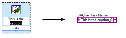
There is already a way to set the name of the task in the present case, but it is not quite obvious and has a little whim. If you change the legend of VI DAQ Assistant express before selecting "Convert to the NOR-DAQmx task", he uses the legend that you specified as the name of the task in Max... and then he adds "_0" at the end:
If you have a suggestion to improve this feature, perhaps you could post it to the Exchange of ideas, information Acquisition?
Brad
-
I have a DAQ Assistant configured to read 2 channels at the same time. When I have a graphical indicator of wire to the output, I see 2 signals mixed together. How I divided them into separate signals?
When I wire any type of indicator, it is show that a release of a single channel.
I want 2 indicators showing 2 different signals as expected from 2 channels configured. How to do this?
I tried to use split signal but it end by showing that 1 out of 1 signal two indicators.
Thanks in advance.
Yes you are right. I tried, but I don't have the result.
I just find the path. When we launch the split signal, we should expand it (split signal icon) by top, not the bottom. It took me a while to understand this.
Thank you
-
How to select the signals from the output of a DAQ assistant
Hello!
I am a new user of Labview 8.5 and I work with a USB-6210. I have two different instruments connected to the same USB device, half of the channels are used for the transducers of pressure where I only need reed and record data, while the other half are associated with TCD detectors where I need to perform an analysis of the signal to get and save the data. I'm in the first stage of construction the block diagram, once I have defined each of the signals that its correspondent of channel using the DAQ assistant, I need to select and separate the signals coming from sensors of pressure from those who come by the TCD detectors, before that I can continue to draw the block diagram. I am using the function select Signal, but I don't know how to do this. Can you get it someone please let me know at least in which manual, I can find a good explanation? I have read the getting started and the LabView user manual, but they have not been very helpful so far.
Thank you!
I fixed it. As you say, I had some mistakes in the thread, but it's working now. Thank you very much for your help! It was very useful.
-
Replacement of simulate signal VI with the DAQ assistant
Hello
I have a VI fucntioning, where signal comes 2 simulate VI signals and is being recorded.
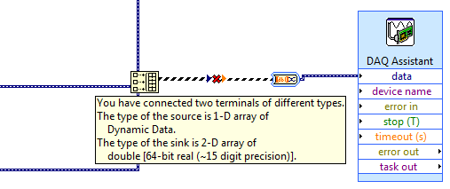
I replaced that with the DAQ assistant. I want to know if the wiring is correct and if it will give me the same result as the simulated VI.
Thank you.
Hello Andy,
Thanks for the reply, yes I did that as well, another way to do it is the 'split signal VI' that automatically separates the signal into 2 channels, most of the high sons being Ch 0
S
-
How to create different types of analog inputs without using the DAQ assistant?
Hi all
I would like to create multiple entries multiple analog channels of type... I mean I want to have the voltage of 5 and 2 channels of temperature...
However, I am not using the DAQ assistant. I use "create channel" vi.
Can anyone suggest me please how to do / I submit my VI for reference... I have 5 tensions, and 2 temperature characterized as showing these 2 two separate graphics...
-
How to use generate multiple signals on a single DAQ Assistant
I am trying to generate several AO on my DAQ card, but I kept getting an error. I looked at the error and he said that I had to use a single DAQ Assistant. So, I created one, but I can't understand how to connect the signals. I get lines that don't connect. Is attached a picture of the installation. Thank you!!!
If you want to use the type of dynamic data, you must use the appropriate function. Do not use the construction. Use the Signal to merge. Then wire you the output of said directly to the Assistant.
-
Simulate signals wired to the DAQ assistant for USB-6009 device
Hello
I'm trying to send a signal to the DAQ Assistant Express VI. I watched the movie "Generating a Signal" on the Web site of NOR (www.ni.com/academic/students/learnlabview/generate.htm) and I have my Signal simulate connected directly on the DAQ Assistant, as shown in this film. In my case, the DAQ Assistant sends the signal to a device USB-6009.
However, I received this message:
Error-200077 occurred to the DAQ Assistant
Possible reasons:Requested value is not supported for this property value. The value of the property may be invalid because it is in conflict with another property.
Property: SampTimingType
asked the value: Sample clock
You select: On-demandIf I select 'On Demand' in my DAQ assistant and run the vi everything works beautifully. However, I need my DAQ assistant to be configured to generate a waveform AC continuous, not output a single alternating current rippling.
What happens here? I did not have this problem before on other devices of NOR. I am using LABView 2010.
Please answer.
Thank you.
-
Hi all
This should be a pretty simple question, but I can't seem to find the answer online and currently do not have the functionality to test this:
I'm using LabVIEW 8.5 and have a VI that imports data from sensor through the DAQ Assistant. In the configuration tab, there is a range of signal input. What happens if my sensor exceeds this range? I get a warning? The default value is the maximum (or minimum)? I was interested in writing a code to display an error that I approach the limits of this range, but did not know if I also need to include code to display an error if the scope is exceeded as well.
Thanks for the help,
Tristan
Hello, Tristan,.
The behavior depends on the selected range and the device you are using.
If you are using a device with a single input range is valid, we will use this range, even if you set a smaller minimum and maximum in the DAQ Assistant. So, if your device only supports ±10V and you set the range to ±8V, you will still continue to get valid data after your top sensor 8V until what you approach 10V. When you reach the limit of the extent of your device, the output will be 'rail', and simply return the maximum value until the signal is less than the maximum value again.
Note: A device that is nominally ±10V usually has a go-around (such as ±10.2V) which are usually specced in the manual.
However, if you use a device with several ranges of entry then things become more complex.
NOR-DAQmx player will choose the smallest range that entirely covers the interval you choose. For example, suppose that your device supports the following input range: ±0.2V, ±1, ±5V, ±10V and you choose 0V - 3V as the range in the DAQ assistant. The NOR-DAQmx driver will focus on the input range and the list of the entry lines that your hardware supports and choose the smallest encompassing the entire range that you set. This would be the ±5V, because this is the only beach that contains up to 3V. Thus, all between ±5V input signal is returned and none outside this range will be 'rail' to the maximum or minimum value.
We do this because using small beaches make more efficient use of the resolution of the ADC. So, we try to use the most effective range based on what you ask without picking up a range that will make you miss data.
Let me know if I can clarify it more.
-
Connection diagram missing in DAQ Assistant generate the signalling block
This is my first post so please excuse the quality of my description.
When I double click on the block of data acquisition - Assistant, there is no tab connection diagram I can access to see how things are wired to the top. I have a NI USB-6211 connected by USB and it is used to control many different sensors and a power supply. Currently, he works for everything and is hard wired correctly, but only blocks DAQ Assistant has a connection diagram available, the other are not. One who has a connection diagram is used to measure a voltage. Others who do not are used to generate a signal. I would really like to be able to see patterns of connection for each block.
-Any help would be appreciated
-Thank you
You can always do like those who never use the DAQ Assistant and read the manual. Right click on the device in MAX and selecting "stitching of the device" works too.
-
I create an executable file to run on a computer that does not have LabVIEW. The problem is that I am using the DAQ Assistant. The hierarchy of the VI is big enough, and I do not know how to include all the required files to eliminate the error "the version of LabVIEw full development is necessary to correct the errors." A picture of the hierarchy of the VI is attached.
I think I'm missing something in the installation. I'm downloading now the DAQmx. I knowticed that all 7 of my missing Subvi are DAQmx * .vi
-
Using the DAQ Assistant. can I create a VI that measures continuously during a fixed time?
I use LabView to an NI USB-6009 enclosure, with two accelerometers like my analog input. When you use DAQ Assistant to build my VI I have not seen an option to measure continuously for a set amount of time. I need the test to run for two seconds and then stop.
Is there anyway to specify the exact duration of each test?
It's about as simple as you can get. Set the number of samples to be twice the sampling frequency (or whatever the multiplier that you want). That's it - a simple DAQ Assistant and nothing else on the block diagram. If you need it to be variable, just wire a control of the number of input samples.
-
DAQ Assistant does not export the values on the scale
Hello all-
Potentially stupid question but here goes: I'm using the DAQ Assistant to read in 4 analog input voltages, continuous sampling acquires data at 10 Hz 1 point, using LabView 12 on a machine with an acquisition of data USB-6341 simulated device (because my office is more comfortable than the lab!). I want to change the first two signals of voltage to temperature and humidity, respectively. I used the «create a new...» "in the 'Custom Scaling' drop-down in the"Voltage configuration"tab for each of these channels, named gave the slope and the intercept at the origin for the respective linear scales and click OK."
When I test the code - and yet once again, I'm not on a machine with a 'real' DAQ system, I use a simulated device, and it seems that NEITHER MAX generates a sine wave of long period with little noise on top for this - I do not get the results on the scale of my 'signal', I get the raw tension. (If you run my code, I will join, the Relative humidity must be between 0 and 100 and temperature-40 to 60, is not 0 to 5, for example.)
So, what happens? Is there some flag or setting that I missed? The scaling only works on voltage data 'real' of a 'real' instrument DAQ, instead of a simulation (which is why I mentioned twice!)? I have to do something in NI MAX as well as Labview?
Thanks for any help you can give.
John Easton
Simulations devices will not respond to custom scale. They are just supposed to allow you to configure your device without errors when you do not have the unit on-site.
"NOR-DAQmx simulated devices create a noisy sine wave to all the entered analog." Simulated data other set-up is not available at this time. »
http://www.NI.com/white-paper/3698/en
They generate a sine with an amplitude equal to half of your specified input range. If you want to work with simulated data that would be more realistic for your application, you could write a VI to generate the data and have a business structure to manage both "simulations" and "real", then you could switch back depending on whether you have access to the material.
I just checked this with a PCI-6254 I install and simulated a PCI-6254.
-
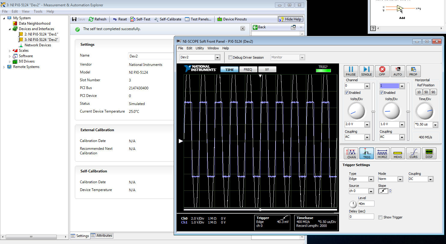
I am trying to create a development machine, where we can test the new code without using our physical hardware. I followed this guide to set up a system of simulation. I get to step 3.2 b, but the device does not appear in the DAQ assistant. MAX, the device self test and gites calibrated successfully, and when I open the test panels, I see some sort of signal. I guess that's a default entry simulated since I didn't that device to look for anything? Note that two devices, I am creating the show upward into the devices section and Interfaces, but that, even after running auto calibrate, automatic Calibration date is not yet specified.
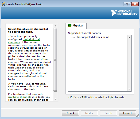
When I try to test the device and create a voltage according to the guide, I can't see a device in the creator of data acquisition task.
Steps 1 and 2 of this guide are of course met. Step 3 is not, but this is not surprising because a simulated device is in device in any case manager. Also, I'm not under RT, so step 4 is satisfied.
Someone at - it ideas?
That would be because the PXI-5124 is a digitizer not an analog input device. You must use the NI SCOPE not NOR DAQmx driver
-
Consecutive calls to DAQ assistant
Hello
I'm working on something that is very probably simple. Maybe the problems stem from a bad initial design choice. The VI (and subVIs) are used at a voltage output, read another tension and react accordingly.
First the error I get is "error-200547.
Here's how the program works:
1 MOVR.vi
This generates two analog output signals, controlled by the same signal generator. There is also a digital signal, but I don't think that's the problem.
2 MTUL.vi (and MDTL.vi)
These use MOVR and read another voltage. Essentially, the voltage must be created until the limit is reached, and he decides to stop.
These two work as expected on their own.
3 IsoMeasure.vi
This is where the problems occur. Basically, this VI take MTUL and MDTL and makes a loop in a loop for, change the frequency of each increment. The observed performance is MDTL will work and try to start MTUL. It's when 'Error-200547' is thrown. The error code appears to be understandable, but "autostart" isn't clear for me using the wizard.
I would avoid using all daqMX code, but I will if I have to. If that's the suggestion, a good example is that sort would be great. If I can put the autostart Assistant, I guess it would help as well.
Thanks for all the tracks. I think it should work.
Hi drevniok,.
The reason why you get this error is that you try to restart your DAQ Assistant several times in your application. One important thing to note is that a task DAQmx configured and started only once each time the DAQ Assistant is called for the first time. Therefore, since you are stop and start the DAQ Assistant, in your application, the second time you call the wizard, it does not start the task. This is made more so by the fact that the function of writing in the DAQ Assistant DAQmx has his automatic starting of entry set to False.
Using the DAQ Assistant for Analog Output returns an error-200547
That being said, the DAQ Assistant is mainly used as a quick and easy to set up and use your DAQ hardware, however, it is a bit limited in functionality compared to the lower levels DAQmx live. This is a case that illustrates this limitation and therefore, I believe that the best solution this problem would be to use the DAQmx LabVIEW vis a lot shipping examples that can help you get started developing your application. These lie in you NEITHER example Finder under the menu help. "" The example I want to show you is the Regeneration.vi Clk - no Cont Gen Wfm - Int voltage under input and output material"DAQmx" analog generation "voltage.
Is another resource, I want to tell you the getting started with NO-DAQmx: Homepage, which are a collection of tutorials online on DAQmx programming.
I hope this helps.
Maybe you are looking for
-
Satellite Pro L40 - 17F: everything by playing the DVD player window flickers
I have a new Toshiba Satellite Pro L40 - 17F with all the updates of Windows Vista (Home) applied. This includes those optional (for example driver updates) I came to be used for the first time (outside the application of windows update) and play a m
-
Unfortunately, I format tool driver when you install window7 and I need graphical tool for the best video shows so please help me
-
My wife needs a outlook account
I have an outlook account and my needs to access his email via my computer
-
I upgraded my card mother cpu ram and hard drive. I reinstalled windows xp home edition has got all of the updates. After 9 latest updates download and installtion was going well until I rebooted the computer and go to page window showing all the ico
-
What is the best way to get fast free music? can someone help please?