DAQ trigger on-the-fly reconfiguration
Hello
What is the correct way to reconfigure a data acquisition on the fly?
Every 100 s I'm doing a 2000 point 4-channel triggered acquisition (sampling rate 50000)
As a function of household, that I also want to monitor the voltage of one of the channels so that every 2 s, I do a single-point acquisition no trigger.
Since I don't have access to a piece of the DAQ hardware, that I have to share channels between the two tasks of reconfiguration on the fly.
(the program is too big / complex to post sorry)
Initialize channels and relaxation (happens once at the beginning of the program):
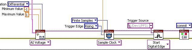
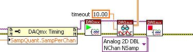
Get data every 100 s:
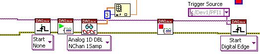
Each 2 s get one sample of multichannel without triggering then restore the trigger:
Please could someone explain when I have to use the 'task to start', 'stop task' and 'commit' aid is rather vague and unfortunately I find myself 'hacking' until it works, which is not the way I like to work! I use a USB-6211.
The above program works OK, but has an intermittent (approx. every 10mins) error on the 'shutdown task"before returning to the trigger. (memory, the description was 'Task not over data acquisition')
Thank you
Al
Al1234 wrote:
... Then this job is stopped and the original task is reconfigured...Al
Simply set up once and just start and stop the job.
I'm a guy sorta visual images will help us to help you.
Ben
Tags: NI Software
Similar Questions
-
Is it possible to filter design on FPGA reconfigurable on the fly?
Hello world
I wonder if it is possible to design multi-channel filters on the FPGA reconfigurable on the fly? For example, it is possible to have X bandpass filters in an iteration, and Bandpass Filters Y with different specifications in the iteration following without having to recompile the FPGA code? Is there a simple way to achieve such a purpose?
I have built such flexibility in the OTR (where each iteration has different filter settings) but hope to implement on the FPGA so.
If someone could provide ideas as to whether or not such a conception is possible, it would be greatly appreciated.
Thank you in advance for your help!
Steven
Hi Steven,
How do you try to generate the FPGA code for this filter, you are using the IP generator?
If so, this knowledge base article describes fixing the coefficients for multichannel to change on the fly filters. There is also a nice example in there also.
Also, if you use this IP generator, this help document describes the more Options box that has the ability to change the coefficients to be 'rechargeable' so that you can change these on the fly it too.
-
 I'd like some help / advice on my LabView program (attached) please. In the VI, the MyVoltageTask_1 is configured as a voltage signal corresponding to a pressure change inside an enclosed cylinder. The signal is transmitted to the BNC 2110 DAQ board / PCI 6133 DAQ card via a differential pressure transducer.

Ideally, the program should trigger as soon as I let air into the cylinder and start acquiring data, and stop as soon as its done. However, LabView does not trigger when I let the air into the  cylinder on the first attempt, but if I exhaust the air and let it in again a second time, the program triggers and I can see a graph of the pressure trace. Please let me know if there is something I should / could change in the program to have the program trigger on the first attempt. Thanks!
Have you try to change the slope falling upward? I begin to take a look at shipping the first examples. "" "Open Finder for example of OR and go to hardware input and output" DAQmx "analog measures" voltage. Take a look to the example called "Acq Cont & chart voltage-Int Clk - Analog Start.vi ' I contains the basic structure of what you're trying to reach.
-
PXI-5421 generating an arbitrary signals on the fly
I have a card PXI-5421. I need to generate an arbitrary waveform with different frequencies. I need to have a trigger to switch between Forms of waves of different frequencies. I use the script to do this. I'm not able to update the frequency of the next wave on the fly without stopping the program. In other words, can I download signals in real time? The code is attached.
Hey Kakrott,
You should be able to achieve this with your PXI-5421. The example of 'switch between the waveforms FGEN"in the examples of LabVIEW makes something similar to what you're trying to do. As explained in the documentation: "this example shows how to switch between two different wave forms while generating, using updated data every time." This example uses a trigger to change what waveform is generated.
-
In the latest versions of FireFox, there's a display option which allowed a change in the size of the fonts and objects on the screen temporarily on the fly. This seems to be missing from version 6. It was very useful and should be added to version 6.
https://support.Mozilla.com/en-us/KB/how-do-i-customize-toolbars
If you mean the - and + Zoom control so it is always there in Firefox 6.0
or
View-> ZoomEdit: I see that you are using Windows 7 where the menu bar is hidden as a Firefox orange button by default. Some menus objects much may not be visible in the menu of the Firefox button. Show the Menu bar or use the - and + Zoom controls buttons.
-
Punch on the fly do not work since 10.2.1
Since the logic 10.2.1. Punch (el Cap 10.11.3) old good on the fly recoding (overlap - replace) Don t work more. Punch in an existing part is cutting one behind the PunchOut! Although the audio is not lost and it is possible to reach the part carried out by hand, but not really an acceptable workflow! Does anyone have the same problem?
-
Header does not get changed when on the fly optione activated.
I tired to change the header of the report using a reminder & it was working fine when I generate the report by keeping the option "on the fly report' disabled. When I try to execute the same sequence with "on the fly report option" on I do not see header information that I could see when "on the fly" option is disabled. I did find the cause and found the following link http://digital.ni.com/public.nsf/allkb/05F43468942BE32E86256D980074E200 but it did not work very well. I was not able to understand the reason of not revealing the header information when "on the fly" option is enabled.
kpraveen,
I looked at the files attached to this knowledge base and saw that they were modified versions of files delivered with TestStand 3.0. Because we have made some changes to these files from this version, there is no guarantee that they will work with the latest version of TestStand.
If you need this behavior in a newer version, you can change yourself the sequence reportgen_ files. You will need create sequences modifyheader and modifyfooter in the sequence thost files, then call these the result of OTF process sequence sequences. We are currently working on a set of more detailed guidelines, and I'll post here when they are available.
-
Hello
I have a question about using the option 'on the fly' and ' "retain the memory and displays most recent result" "option. As I undertood the support of NEITHER and Teststand documentation, the option 'on the fly' allow you to present your results during the execution of your test. It also allows the RAM used remain constant because after each step, the ResultList should be released.
So. It is the theory. In practice, I increased my RAM used regardless of the settings I use. Because I use tests which are conducted for several days, the collection of results makes the RAM increases so much that Teststand cling or works really very slowly, if it is not crashing...
I did a few tests (see attachment). By setting different options, I run my test why SequencialModel for 1 minute and measure the RAM before and after execution. (the first time just before I have that on the "OK" button of the dialog information of the object to be measured, the second time just after I put an end to the hand in the execution of the test). Between each test, I restart Teststand. I measure the RAM using Windows Task Manager.
My PC is a Win XP SP2 and I use Teststand 4.1.1 (but the problem still exists Teststand 3.5...)
Test 1:
'on the fly of statement' option NOT selected
the "keep memory and only the last results display" option is NOT selected
Report type is ASCII and all results must be reported
Task Manager:
Used RAM at the beginning: 651 MB
Used RAM after a minut: 716 MB (+ 65 MB!)
#Results: 31420
==> + 2, 12 MB/result
Test 2:
'on the fly of statement' option selected
the "keep memory and only the last results display" option is NOT selected
Report type is ASCII and all results must be reported
Used RAM at the beginning: 646 MB
Used RAM after a minut: 681 MB (+ 35 MB!)
#Results: 4969
==> + 7, 21Mo/result
Test 3:
'on the fly of statement' option selected
the "keep the memory and display only the most recent results" option selected
Report type is ASCII and all results must be reported
Used RAM at the beginning: 662 MB
Used RAM after a minut: 681 MB (+ 19 MB!)
#Results: 4969
==> + 3, 24MO/result
Conclusion:
Selected by the "on the fly report" with or without the option "Maintain the memory and display only the most recent results", the RAM used by each result is greater than if you do not select the option "on the fly report." Also probably Teststand generates the report at run time, but independent more important on the parameters of the RAM option is ALWAYS increasing.
So is this a bug or is this a feature?
Does anyone have experience with the "on the fly report?
Bye,.
Risotto
Hi Norbert,.
Thanks, thanks and thanks again! It was the solution!
If you set "on the fly report" + "keep memory and only display last results" AND activate 'Throw results or disable results when not required by model' then the behavior of the RAM used is as you explained: it begins to increase, but after some time remain constant.
With her so I have a solution, very well!

Only comments in support OR in general this option seems to be implemented in Teststand for several years (Teststand 2.0 can be?) and I spent weeks already on the search for a solution to this problem of memory. OK, maybe I was really long to understand how do, but on the other side I spend so much time reading of the documentation, speaking with the support of NOR and the support OR so past time send me examples and documentation. I think for a question like how to manage reports and the memory of test which are lasting several days, support should be able to give me an answer and it must be clear in the documentation how to make the adjustment.
In any case, I'm happy you could have help me. Thank you once again!
Risotto
-
4462 PCI gain is editable on the fly in VB 2005 express?
Hello
My current setup of chanil comes from shape:
myTask.AIChannels.CreateVoltageChannel (physicalChannelComboBox.Text, "", _)
AITerminalConfiguration.Differential, Convert.ToDouble (minimumValueNumeric.Value) _
Convert.ToDouble (maximumValueNumeric.Value), AIVoltageUnits.Volts)Where 'physicalChannelComboBox.Text' = ' Dev1 / AI0:3.
This creats all channels at the same time, but I need to have different voltages, Min and Max.
This is a MAX 4462 configuration.
I'm doing this configuration in VB
MajorVersion, MinorVersion DAQmx]
8 6 [DAQmxChannel] AI.Coupling AI.Max AI.MeasType AI.Min AI.TermCfg I.Voltage.Units ChanType PhysicalChanName PPI2/PrimaryVolts DC 42 Voltage -42 Differential Volts Analog Input Dev1/ai0 PPI2/PrimaryCurrent DC 0.316 Voltage -0.316 Differential Volts Analog Input Dev1/ai1 PPI2/SecondaryVolts DC 31.6 Voltage -31.6 Differential Volts Analog Input Dev1/ai2 PPI2/SecondaryCurrent DC 0.316 Voltage -0.316 Differential Volts Analog Input Dev1/ai3 [DAQmxTask] Channels SampClk.ActiveEdge SampClk.Rate SampClk.Src SampQuant.SampMode SampQuant.SampPerChan SampTimingType Rising 195000 Continuous Samples 2000 "" Sample Clock PPI2 PPI2/PrimaryVolts, PPI2/PrimaryCurrent, PPI2/SecondaryVolts, PPI2/SecondaryCurrent[DAQmxDevice] BusType DevSerialNum PCI.BusNum PCI.DevNum ProductNum ProductType Dev1 PCI 0x127B518 0x5 0x6 0x7170 PCI-4462I wish I could watch the values of data in time and change the gain/rainge of each channel while he was still recording data. How can I change the gain on the fly.
Thank you.
JohnYes, it will work.
Remember that you cannot change AI Min and Max during execution of the task.
Well well... unless you will not see a difference when runningGavin Goodrich
Software engineer
National Instruments -
New Daq with the Daq Assistant in the filtering code
Hei,
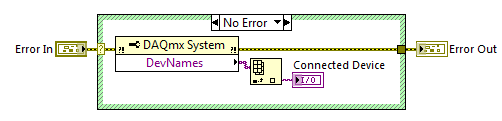
I have a NI USB-6225 DaqMx I used a couple of years. When I started with LabVIEW, I found the Daq Assistant to the best way to measure the voltage with my Daq etc. My company has purchased another DaqMx NI USB-6225 and now I have a big problem: the Daq Assistant in my old Vi does not work with the new data acquisition. I understand why there is this problem, but I do not know how to solve. I found this code on the forum who finds that Daq is connected:
The problem is that Daq Assistant do not have an entry for it, and it gives me an error if I try to run the code with a different device than the original, I used when I created the code.
Is there a way to solve this, so I don't have to convert all the Assistants Daq normal code?
Hello again,
two options:
(1) as the old software is related to 'Dev1' you must rename your new device to this alias and skip/rename the old device (and lack).
(2) rewrite your old software does not become is not dependent on the name of the alias for the data acquisition card...
It's your choice!
-
Starting assistant DAQ prior to the main version of the program
Hello
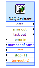
I would need to begin to acquire data via the module Wizard DAQ 100ms before my main program in the while loop starts (see attached photo). How could I just realize this (without having to include the DAQ assistant in the while loop itself)?
Thanks for your help,
Thibault.
Put a picture of flat sequence between the beginning of mx DAQ and the while loop. Connect the wires of error through it. Put a wait 100 ms function in the frame.
-
How to generate a trigger when the arbitrary
Hi all
I have a digital output pci card 6534 and an analog output pci card 6723.
I would like to generate a material long pulse sequence timed. The 6534 has 32 MB memory on board, so it is good to do a long sequence. The 6723 will run out of memory if started at the same time. I would therefore trigger the 6723 at a later date. The boards are connected with rtsi.
I see 3 ways to do (well that I know how to do, but the first two would be more elegant):
(1) generate a sequence of digital pulses on ports (i.e. how that), then convert a line of port online rtsi (don't know how to)?
(2) generate a trigger to the arbitrary point on the rtsi lines (don't know how to)?
Go 3) with 1) physically connecting a port to a line PFI on the analog card.
I have not found a way to send a trigger at some arbitrary point with the RTSI. Instead of this I went with solution 3) and related digital outputs analog card PFI channels.
-
The original loop iteration after receiving the trigger of the PXI-6652 pulse
Hello world
I apologize if this has been answered somewhere else, but I'm having a hard time finding examples and tired after a long day of work.
in any case, I use a PXI chassis with a PXI-7854R FPGA Board and module synchronization PXI-6652. I have the FPGA biphasic pulses being generated at 8 analog channels. I want to be able to do is to send a trigger (say at 1 Hz) for the PXI-6652, which begins at the exit of the biphasic pulse on the FPGA. I'm running the FPGA through a host program as the variables on biphasic wave will change based on the current experience.
So, in short, I was wondering how to generate a trigger of the PXI-6652 pulse and then use this trigger in a host of VI to start an iteration of a loop. It seems simple enough, so any help would be appreciated.
Thank you, and I can post the code tomorrow if necessary.
To answer your second question, Yes, the driver NOR-SYNC 3.3 is available for download and use with LabVIEW 2011.
As far as use the PXI-6652 to start the acquisition on an FPGA VI, we have enough good examples provided with LabVIEW that will show you how to proceed. To actually generate a trigger with NO-Sync, there are several examples in the Finder for example of NOR (help > find examples) which send a trigger one of the PFI lines to be used with the other modules. You can search for OR Sync and they all appear here. You need this driver installed first before you see anything, however.
Also, if you look through the viewfinder of the example under Hardware Input and Output > R Series > FPGA Fundamentals > triggers and guard dog, you will find an example of triggering good enough it for use in your FPGA code.
This example uses NO-Sync to trigger a device of the M series, which is not relevant to what you are doing (he uses DAQmx), but there is a very good example of generation OR-Sync trigger here who I think can help.
-
input analog trigger on the door of the meter to measure the frequency of generation
Hello
I want to measure a frequency on the analog input, but it doesn't seem to work.
I'm trying to work with DAQmx with the use of the ansi c standard.
The first step, I've done was acquiring information on the analog input. With the use of a simulated device, it shows a sine wave on the entry.
My next step is to generate a trigger for the meter signal, but this doesn't seem to work.
I don't see how it is possible to connect the trigger on the entrance to the analog meter.
For the creation of the analog input and relaxation, I use the following code:
DAQmxErrChk (DAQmxCreateTask("",&taskHandle));
DAQmxErrChk (DAQmxCreateAIVoltageChan(taskHandle,"Dev1/ai0","",DAQmx_Val_Cfg_Default,-3.0,3.0,DAQmx_Val_Volts,NULL));
DAQmxErrChk (DAQmxCfgSampClkTiming(taskHandle,"",10000.0,DAQmx_Val_Rising,DAQmx_Val_FiniteSamps,1000));DAQmxErrChk (DAQmxCfgAnlgEdgeStartTrig (taskHandle, "Dev1/ai0 ', DAQmx_Val_RisingSlope, 0 '"));
For the creation of the meter, I use the following code:
DAQmxErrChk (DAQmxCreateCIFreqChan (taskHandle1, "Dev1/ctr1", "", 1 January 2000, DAQmx_Val_Hz, DAQmx_Val_Rising, DAQmx_Val_LowFreq1Ctr, 1, 4, ""
 );)
);)I hope someone could give me a hint.
I also tried the examples that come with DAQmx but well I know this are only examples to counter with the help of the digital inputs.
Thanks in advance.
Hello
You must use the exit event of comparison at the entrance of the meter. Change this property after the configuration string function.
DAQmxSetChanAttribute (taskHandle1, "", DAQmx_CI_Freq_Term, Dev1/AnalogComparisonEvent);
Kind regards
Bottom
-
Injection containers QML on the fly?
Hello, I'm quite new to the Blackberry development, so far, I can say that I love it. I'm working on an application that requires me to be able to change the QML that is inside a container on the fly. For example:
        // MAIN CONTAINER PLACEHOLDER
        Container {
            id: mainContainer
            // Any way to inject fully built qml files right here, and swap them out on the fly?
        }
I have a menu on the left in the form of a ListView when you press a button at the top left, the current view moves to the right and allows you to use the navigation. When you select a new navigation item, I want to replace what is in the "key container" with the QML file that is appropriate for what the user has selected.
Thanks in advance for any help!
You're better off using a delegate control for your particular problem.
Take a look at the example of Cookbook qml stunts to see how it is easy to do.
Maybe you are looking for
-
ESR 31 to 38 ESR FX Fx update reach the functioning of business Web applications?
HelloWe're set ESR Firefox as default browser in our society. Before we have tested and updated our desktop tools to make sure they work and is displayed correctly with FX. We tested with FX ESR 31.3. After the recent release, we now hesitate what ve
-
My iMac will not fall asleep, well put me in mode 'sleep' manually or automatically after 10 minutes of sleep. The screen will be disabled for a few seconds up to a minute and then wake up to the top. I have restored the default settings in the energ
-
I lost my browser by typing sound when clicking on a Web link.
How can I get tapped his return when a click on a Web link.
-
Light LED Notofication won't notify after viewing notifications from the lockscreen he
Sony Hi community, There are already a lot of questions posted here, but so far, I missed only the mode of stamina and endurance Ultra mode from the previous version. My device is running the latest put updated sw (23.5.A.0.575). A few things, howeve
-
Impossible to get official site Chipset drivers
Hello. I reinstalled windows on HP Pavilion G6 - 1311ea B1Z97EA #ABU. I had all the other drivers sorted out but I still get the problem with "PCI Device" and "SM Bus controller". Could I get links to where to get them? Thank you.