DAQmx create track (I-current-Basic) 8 channels with different values of Shunt resistance
Hello
I want to measure 8 current channels with different values of Shunt resistance.
Problem: The channel create DAQmx (HAVE current Basic) specifies that a value of Shunt resistance.
How can I set the value of Shunt resistance for each channel individually?
Concerning
Marcel
Hi Marcel_C,
Take a look to get attached.
Best regards
Mencef
Tags: NI Hardware
Similar Questions
-
Several channels with different frequencies
Hello
I use card NI USB-6221.
The C API using, I need to generate 6 digital output channels, with frequencies of diffrenet and Heavy duty.
To be more precise, the 2 are totally identical, but I need them to be reversed, and the other 4 are similar to another, but should be shifted in time (I.e. There is a delay between each of the channels).
I used the 2 channels of CO that the USB-6221 takes charge for the first two signals, and it works very well (the two signals are synchronized and are reversed).
Now I need an additional 4 channels for the other vague square.
I saw an articale NOR by JohnP web site with the title:
Generate multiple channels of digital output with different frequencies and Heavy Duty
The following example shows how to create and generate a digital with the non-regeneration wave form so that you can change the frequency and the duty cycle on the fly with the M Series DAQ hardware X. The example uses output digital rather than counters to achieve this, so if you need more output than the available counters, it would be a good option (Note: on the materials of the M series an external sample clock must be provided, this may be caused by one of the counters if you want).
that seems to be exactly what I need, but the examples are for LabView which I did not.
Can someone explain how to do this with the C functions?
Best regards
Danny.
Hey Danny,
The important thing to note is that you can clock of arbitrary digital waveform (up to 1 MHz on the 6221). The real data acquisition programming is pretty easy once you have the waveform. My Example LV used LabVIEW Base generating function VIand then converted to a digital waveform to generate the signal from each channel.
The functions of LV helped tremendously with to achieve the waveforms to be updated on the fly (the basic function generator keeps track of phase for you).
If you do not need to be updated on the fly, then the construction of the waveform in C should not be too bad. For example:
P0.0 [1 1 1 1 1 1 1 1 1 1 0 0 0 0 0 0 0 0 0 0] * 1
P0.1 [0 0 0 0 0 0 1 1 1 1 1 1 1 1 1 1 0 0 0 0] * 2
P0.2 [0 0 0 0 0 0 0 0 0 0 1 1 1 1 1 1 1 1 1 1] * 4
P0.3 [1 1 1 1 1 0 0 0 0 0 0 0 0 0 0 1 1 1 1 1] * 8
[9 9 9 9 9 3 3 3 3 3 6 6 6 6 6 12 12 12 12 12]
The table above U8 would give you 4 output waveform of 50% duty cycle at Fs/20, shifted 90 degrees to eachother. The lines would be p0.0 by p0.3 (the bit rate of the U8 corresponds to what line goes high).
Best regards
-
Two tables with different values of basic on an analysis filter
Hi guys,.
Let assume that I have an analysis with columns: group_id and sales.
On this basis I would like to create two tables: table1 where group_id = 1 and table2 where group_id = 2.
OBIEE is able to do?
Kind regards
SlaviHi Slavi,
You can do it in a single analysis, but you have to have the column with group_id twice.
Bring, group_id_1, group_id_2 (same column), sale
Now in table 1.
bring group_id_1, sales
Then in the selection steps for group_id_1-> select members-> Action choose keep only-> choose the value of the filter 1
This will filter the table 1 with group_id 1
In table2 group_id_2 porter, sales
Then do the same step for group_id_2 with the value 2.
You now have two reports with different filter in the same report.
If you want you can keep the same name column for the two columns group_id, I just kept group_id_1, group_id_2 for easy reference.
-
Replace negative values in multiple channels with "0'.
Hello
I'm calculating and then by creating a cumulative channel, multiple channels. Negative values in these channels aren't necessary, and I need a nice way to replace each negative value in these channels with a value of '0'.
My current code is:
Do
Do
If Data.Root.ChannelGroups (2). Channels (i). Values (II)< 0="" then="" data.root.channelgroups(2).channels(i).values(ii)="0 ">
II = ii + 1
Loop until the second > Data.Root.ChannelGroups (2). Channels (i). Properties ("length"). Value
II = 1
i = i + 1
Loop until I > Data.Root.ChannelGroups (2). Channels.CountIt works, but I don't like. He adds a few seconds when running my script, which was almost instantly. Is there a better way to do it?
Thank you.
Hello Kevin,
The fastest way to go through a channel and check the values less than or equal to 0 is through the canal's calculator. The code below takes all the channel first channel group (with the exception of the first string that is be the weather channel in my example data set) and replaces the values<0 with="" 0="" through="" the="" iif="">
Set Group = Data.Root.ChannelGroups (1)

iMax = Group.Channels.Count

FOR i = 2 to iMax

  Adjust the strings = Group.Channels (i)

  Formula = "= IIF (y '.<0, 0,="">

  Call to calculate (formula, Array("y"), Array (Channel))

NEXT ' I
In this example we overwrite the existing values of data channel with 0, but you can also copy the channels to make sure that your raw data is available.
The calculator of channel is extremely fast for this type of operation because it does not create a loop to go if each line separately and check the values he...
I hope this is useful,
Otmar
-
I use the outgoing/incoming analog DDK with the DAQ 6341 SMU map.
The examples, for example aoex5, show a single timer (method outTimerHelper::loadUI), but the example shows the DMA loaded with same size of vector data.
There is a comment in the outTimerHelper:
 call rogramUpdateCount, which implies that memory sizes different pad per channel can be used.
(the comment is: switching between the sizes of the various buffers is not used)
Nobody knows what should be the format the DMA buffer for data from multiple channels with different frequencies?
For example, we want a0 with a sinusoid at 1 kHz and a1 with a sine wave of 1.5 Khz. What looks like the DMA buffer?
With the same frequency for each channel, the data are interleaved, for example (ao0 #0, ao1 #0; ao0 ao1 #1, #1,...), but when the frequencies for each channel is different, what the stamp looks like?
Hello Kenstern,
Data are always intertwined since each card has only a single timing for each subsystem engine.
To AO, you must specify the number of samples that will be released to the AO. You also specify the number of channels. Because he didn't is that a single engine timing for AO, each AO will be channel will be updated at the same time to update clock tick. Data will be interlaced exactly as shown in the example because each channel AO needs output at each tick of the clock to update. The data itself can change depending on the frequency you want to copy.
kenstern wrote:
For example, we want a0 with a sinusoid at 1 kHz and a1 with a sine wave of 1.5 Khz. What looks like the DMA buffer?
With the same frequency for each channel, the data are interleaved, for example (ao0 #0, ao1 #0; ao0 ao1 #1, #1,...), but when the frequencies for each channel is different, what the stamp looks like?
In your example, you must come with an update rate that works for the two waveforms (sine waves of 1 and 1.5 KHz). To get a good representation of a sine wave, you need to update more than 10 x faster than your fastest frequency... I would recommend x 100 if possible.
Update frequency: 150 KHz
Channels: 2
Then create you stamps that include complete cycles of each wave you want to produce based on the frequency of update. These buffers must also be of the same size.
Buffer 1: Contains data for the sine wave of 1 KHz, 300 points 2 cycles of sine wave
Buffer 2: Contains data for the sine wave of 1.5 KHz, 300 points, 3 cycles of sine wave
You can Interleave them as before. When the data are performed through the ADC, they are out different sine waves, even if the AO channels are updated at the same speed.
-
Write to digitall all ports (channels) with the decimal value
Hello
It is possible to write all digital channels with a value decimal for a device with 96 channels at the same time?
I have a USB-6509 camera and I want to write each value of Pentecost bit 1 in the loop (for the first transfer I write 0,1,2,4,8,16, 32, 64 and 128) with the line "Dev3/port0 / line0:7", but if I want to write all ports at the same time, how to set the line and the "write.vi DAQmx?
Thank you.
You can configure the reading and writing in the ports of 8 bits with the 6509. For example, you could write just 128 to "Dev3/port0. If you want to write to all 12 ports, I recommend doing a task that is several channels on the 6509 module, each channel of the task being a port. You can then use the channel Multiple, single sample of writing of your values. Your values must be in a table of U8.
-
Possible bug: DAQmx create channel w/o specified in task
The VI DAQmx 'DAQmx create channel (I-voltage-Basic) .vi' requires no task should be connected, and claims his detailed help "" task in specifies the task to add virtual channels, this VI creates. "." If you do not specify a task, NOR-DAQmx creates a task for you and adds the virtual channels that this VI creates to this task. »
My recent experience, I think that there is a problem with this feature. If no job is specified, sometimes this VI will create a new task without problems, but other times it will overwrite an existing task, causing errors later when you try to reference the crushed tasks.
In my code, I have 7 tasks, two digital (DIO), an analog to (HAVE) and four analog out (AO). One of the AO and the tasks of the AI does not use a task VI before the channel VI create. I recently added this AO task without creating a new task manually, based on the reproduction of legacy code for the channel of AI that also not create a new task. With two spots missing the task of creating VI, I found it fairly common (20% of the tracks) a further task would be crushed, causing errors when the task has been used, either be the wrong type IO, a wrong number of channels, etc. I think I saw this error until I added the second task without creating a task, but it's so rare that he didn't pay much mind, and I would just restart my VI. Now that was occurring more often, I've been tracking it. Simply by adding 'DAQmx create Task.vi' before calling Create Channel and the new task of wiring in the task, the problem seems fixed.
It is easy to add to create a task to avoid this problem, but it seems to me that the detailed help for Create Channel indicates that it is an unnecessary step. Thank you.
Hi MDI - AJT.
This looks like a problem with the code you posted, by suggestion of Norbert. When you create the task handles, you should do this only at the beginning of your code outside the loop, otherwise you will create errors that you overwrite memory locations at each iteration. If you move your virtual channel calls create outside of your loops, and does not call the handle of the task to be authorized beforehand (and implicitly create the task rather than explicitly), then this behavior must stop.
I recommend to try this with a single line, and not 7 DAQmx calls and follow the DAQmx architecture as seen in the examples under 'Help' "'find examples' and see if this behavior persists. Later architecture, I was not able to re-create this behavior.
BeenCoughin
-
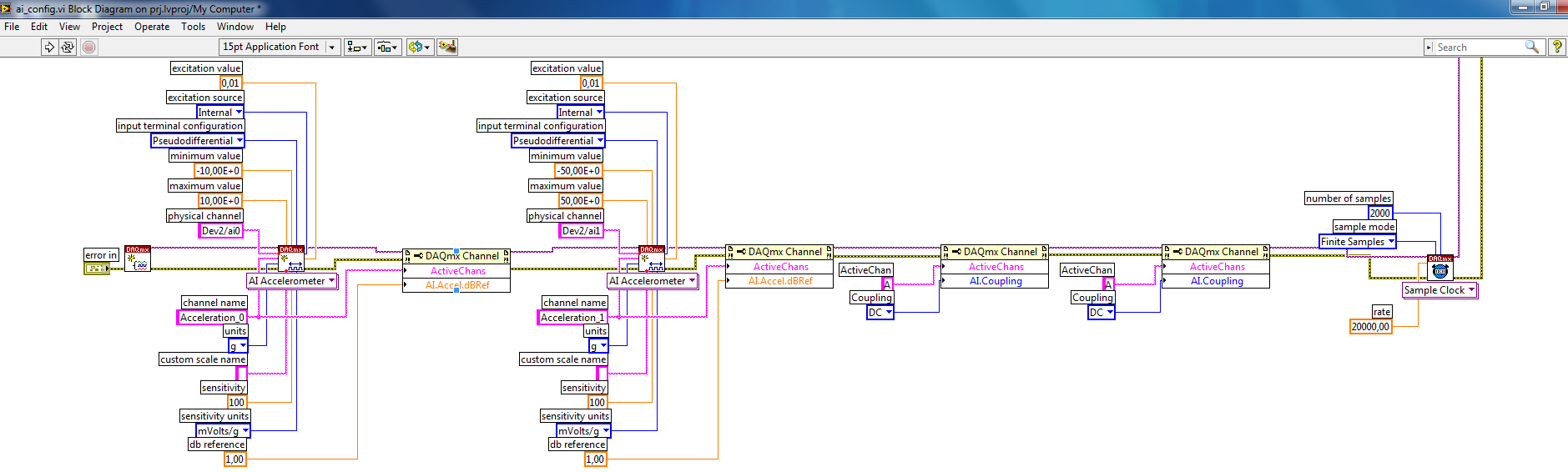
Error-200431 occurred at .vi DAQmx Create Channel (I-acceleration-accelerometer)
Hello
I tried to use DAQmx Create Channel to accelerometer and yet it responds with error (see below). When I use max OR to measure the accelerometer (I-acceleration-accelerometer), there is no error, and I see that acceloremeter works.
OR PXI-1042 and I use OR-4462 card to measure vibration vith acceloremeter.
Error-200431 occurred at DAQmx Virtual Channel Create
Possible reasons:
Physical channel selected does not support the type of measure required by the virtual channel you create.
Create a channel to a type of measure that is supported by the physical channel, or select a physical channel that supports the type of measure.
Property: I. MeasType
Requested value:
You can select: sound pressure, voltage: Microphone, accelerometer, Position: Eddy Current proximity probe, Force sensor: IEPE, speed sensor: IEPETask name: _unnamedTask<104>
Hi serdaryilmaz,
I'm not sure why the accelerometer mode does not work, but it works very well in normal mode - it maybe has to do with the accelerometer, you? Whatever it is, if it works with the voltage mode, I am happy that we found a way to make it work. Is this an acceptable work around you?
-
DAQmx create virtual channel (VI) error-229771 reports
Hello
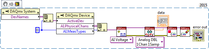
When in a project that I am working to get error-229771 code whenever I try to run 'DAQmx create Virtual Channel (VI)' this does not happen when I create a vi not in a project. The problem is that this project is very large and it if poster impossible to recreate. It's several hundred vi. Y at - it something that I missed in the forums and support that could explain this. I created the VI below in the project and outside the project. In the project, the error occurs outside the project, it runs without any problems.
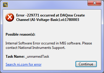
Message:
229771 error occurred at .vi:1780003 DAQmx create channel (I-voltage-Basic)
Possible reasons:
Internal software error has occurred in the MIG software. Please contact the support of National Instruments.
Task name: _unnamedTask
Any help would be appreciated. Thank you, Matt.
LabVIEW version: 15.052(32bit)
OR Max Version: 15.0.f0
NEITHER DAQmx Verson: 15
OS: windows 7 service pack 1
PC: Intel Core i7-2600, 8 GB of ram
Data Aquistion: NEITHER DAQ USB-6289 calibrated June 2015
This code snippet returns the name of the first channel of analog input on the device first, and then tries to create a task for her. The bed of the canal, then close the task.
Error message
Hi Matthew,
Thank you for following up after you fix your problem. I'm glad to hear that you do not encounter this problem more.
Here is an article that lists the reasons for this error (although unfortunately, I cannot pin down which is the exact cause in this case).
http://digital.NI.com/public.nsf/allkb/03123D0E8A36C48E862577A4005B6BAA
NOTE: This article specifies that the error occurs at startup task VI DAQmx. You do not use the start task VI, so the task starts automatically in the DAQmx Read function. The error will occur instead in the DAQmx virtual channel create, that you encounter in your error.
I hope this gives you an idea about what could have gone wrong, and I'm sorry he is no more details.
Good programming!
-
DAQmx - create channels to channel-not found
Hello
I'm new to labview. So maybe my question is simple...
I want to generate a signal. That's why I use the DAQmx-create channel.vi. I have, I've created a control to selected the channel, where the signal is generated. But no channels are found.
I use 5412 PXI and my camera is visible in MAX. So I don't know what the problem is. Can someone help me?
Thank you
Ratta
The 5412 is an arbitrary signal generator. It does not use DAQmx. It uses NEITHER-FGEN.
-
What channel DAQmx property corresponds to "name" entry "DAQmx create Channel.vi?
Hello people,
I am changing a program, I have inherited so that it uses DAQmx virtual tasks rather than have the task and the channels created by programming of in the code.
In the existing code, the entry 'name' on the 'DAQmx create Channel.vi' is wired with a value. When you use a virtual task DAQmx, I do not use the 'DAQmx create Channel.vi', but I still want to set the values of the "name" in the code with the help of a property DAQmx node. However, I can't find a property called "name". Such a property exists with a different name?
Best regards
Chris
-
Error-200431, DAQmx create Channel .vi (I-voltage-Custom with excitement)
Where is past ".vi DAQmx Create Channel (I-voltage-Custom with excitement)?
I tried to use this VI of force measurement with an NI PXI-4472. He responds with the 200431 error... You asked: more: voltage: Custom with excitement, you can select: sound pressure, voltage: microphone,...
It seems to me to be an internal error of the VI's Version of LabView 8.6.1
Hi Suse,
Thanks for your reply.
It's the right device but the bad VI.
PXI-4472 is an excellent camera for the dynamic force measurement using Quartz sensors. I was intending to use the .vi (I-voltage-custom with excitement) to configure entry and IEPE excitement, but I got the error code. I have now managed by using the pure (I-voltage) .vi entry configuration and IEPE using the DAQmx channel property node.
However, I tried the .vi (I-voltage-Custom with excitement) with appropriate PXI-4220 simulated device, no error.
Concerning
T.Knox
-
You can use your apple TV without an internet connection? If so, how do install you it? I have currently basic cable and that you have a wireless router. Thank you
What you want to do with the ATV without an Internet connection? It is designed as a device of Internet broadcast, so you can access online content via the big screen in the living room rather than the pocket computer in your pocket...
technically I think its possible but you would still need an Internet connection for the installation and update of the software process and even less to download applications and games, but if you don't have an Internet connection apps/games will probably not work. I don't think that there is 'out of play'...
-
How to use DAQmx create linear scale
Hello. I have an output of an amplifier which is 10 mV/V, which is read by a USB-6002. This amplifier voltage range is 0 to 200 volts. Have tested the DAQmx create scale Vi, I don't understand how it works. Looked at the other posts here for answers, I still haven't understood how it works. As a first step, it says that it uses the y = mx + b equation for it. I don't know what the slope refers to except if it is the angle of the line. If someone would have an example that explains how it works, it would be great. I also tried to look at an example but could not find one. Thank you
Here is an explanation "improvised" y = mx + b. If you think of 'x' as the input and 'y' as output, then you can consider "m" as the gain, and "b" corresponds to the offset, the output that you can read with zero entry.
If you think of this equation from an amplifier, many are designed to have zero output when there is no entry. In other words, b = 0. If you have a gain of 10 mV/V (which I guess means that a 1V input would give an output 10mV, then m, usually called "the slope" (which is the slope of the curve of output), serait.010/1 = 0.01.)
Note you describe the range of the amplifier as 0-200V, so the output will be 0 - 2V, well inside the ±10V USB-6002.
Bob Schor
-
Hello
I'm trying to control the timing of a timed loop. So far, I have tried several approaches via the software and which worked very well except the time loop in some missed cases 1-2 Ms I want to make sure the timing is right. I tried to provide an external clock through the acquisition of data I. The system I use is NI USB-6212. It has two counters and DIO and AIO, but I keep getting errors. I tried two different approaches. One was to use directly the game 'DAQmx create calendar Source.vi' in frequency mode, and when I did, I got error 200077. Then I found a post of somone saying that sometimes it is not possible and an alternative method is to use the same vi but set task of loop control mode. This one gave me Error200452. For this one you will see in my attachment the suggestion was to use an AI then the moment of him and then use this task for Creat DAQmx synchronization Source.
I don't know what the problem is or if I need to put something differently.
Please let me know if you can help me with this.
I'll try to continue to work on that, but if anyone of you a suggestion I'll be very happy to consider the issue.
Thank you in advance,
Best, Massimo.
Massimo,
In my view, the errors that you see are the result of your hardware USB-6212 is supporting the functionality of the task control loop. I have a M Series PCI card that is capable of operating both of your screws attached without problem (although they still +/-1ms variation on occaision). When I try to use a USB-6212 simulation, I get the same error codes that you do. Unfortunately, it's just a case of a lack of equipment.
Kind regards
Maybe you are looking for
-
My iPhone 6 is disabled and I would like to save it on iTunes but it asks for my password.
My sister locked my iPhone while I was out for the weekend, I connected to iTunes (which has my backup to iCloud) hoping to save, but it asks for my code to access/Word. I have spent a lot of time watching the guides and support systems different, bu
-
I can't download a game. Said, my windows user account does not allow. I was a member of the site of the game for years and I do not know why I can not download all of a sudden. Please help, thanks
-
Result of vulnerability analysis shows Sun Java JDK / JRE / SDK Multiple Vulnerabilities
Analysis of vulnerabilities by Kaspersky Anti Virus showed Sun Java JDK / JRE / SDK Multiple vulnerabilities in my laptop Vista Home Basic 32-bit computer. Looking for solutions for
-
Yahoo Messenger stop seconds on identify you?
Yahoo Messenger
-
How can SYSTEM partition is almost full - I know what is there?
My SYSTEM partition is 100 MB and has only 12 MB free. How can I know what all the space is used for? The reason why I worry about it, it is that prevents Microsoft backup to create an image of the system; There must be no more than 50 MB in use the