Data delay FlexRio (generate i/o of delay)
Hello
I use SMU-7961R + module NI 6583. I want to implement a synchronous digital communication IPs and I need control the master data of the clock delay.
To contact a master external IP address, I use the struc timed loop with a clock source the strobe line where I connect the singal clock. The result is satisfactory: each master clock climbing aboard, data are generated with a specific constant delay.
I have to control the delay (in the loop of the single clock cycle). This delay does not exceed 1 master clock cycle.
In this case, the best is to include the buffers in the i/o path to the longest path... How can I implement this in LV FPGA...
Note: Master clock isn't contineous.
Thank you.
Kay.
Hi Marjorie,.
Unfortunately, the maximum number of cuts will limit the total range of 5ns max, however 5ns is a period of clock at that point, you should be able to delay your data in the SCTL in LV FPGA.
With respect to the generation on the falling edge, you have two options.
The first can be done in LV FPGA but it's a little hard to explain. To build on the falling edge, we would first put the module in double data rate mode. Then, it will generate over and fronts. In order not to change the samples on the front, on the rising output must match the value of dashboard falling from the previous iteration of clock.
For example, suppose you wanted the following values in the output order: T, F, F, t. you have to give a value for the rising and falling each iteration of the SCTL edge.
Iteration 1:
Rising - F
Fall - T
Iteration 2:
Rising t
F down
Iteration 3:
Rising - F
Fall - F
Iteration 4:
Rising - F
Fall t
The one caveat to this approach is that you could generate only at 150 MHz DDR max of 300 MB/s.
Another approach would be to reverse the polarity of the strobe in the CLIP 6583. This would require a VHDL work but definitely would make the LV FPGA implementation somewhat easier. Reverse the strobe clock in VHDL would also allow the refresh rate of 200 MHz.
I hope this helps!
Tags: NI Hardware
Similar Questions
-
Hello
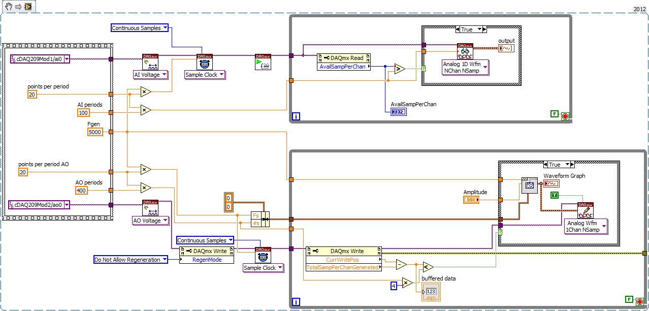
I 9184 cDAQ chassis with two modules installed: NEITHER 9215 (HAVE) and NI 9263 (AO).
AO generates the signal of 5 kHz and bought it. Initially, all right, but after 20-30 seconds, it has delays (up to 30 seconds!) between the production and acquisition.
Time lag depends on the speed of the DAC. If it 20 * 5000 = 100 kHz, delay = 15 sec, if it 10 * 5000 = 50 kHz, the delay is 30 sec.
It works with the PCI - DAQ version, but I do not understand why he has these delays with ethernet chassis.
I tested it on gigabit ethernet with chassis directly connected to the host. But I don't think that problem is on a network, because the net charge is 0.55% and ~ 1Mb\s data transfer. The processor is also low.
And I think evil isn't in the generation, acquisition, as it evacuates all samples in buffer (number per channel in DAQmx read nearby 'availsamplesperchan') and because changing CAD rate influence on signal updates.
In addition, it works fine without these big delays to signal lower rates, for example, sine wave 50 Hz generating.
Example of code is to join. I read 100 times of 5 kHz sinusoid, 16 points per period (refresh rate = 80kHz, 1600samples). And 5 kHz sine generation of 100 periods with 20 points per period (rate is 100 kHz, 2000samples).
Now, this works in two separate loops with the control "TotalSampPerChanGenerated".
Problem was with a buffer too small mailing to cDAQ. 8 k samples and 4 caching works pretty stable buffers.
Also, I checked the difference between 'CurrWritePos' & 'TotalSampPerChanGenerated' and the maximum value is 1 500 000. 1 sample is it DBL, it really means that the buffer size is 1.5 M * 8 bytes = 12 MB.
Thanks for the thread.
-
Dates to be generated in a sequence
Hello
A date as to_Date('05-june-2012') should be geneerate a sequence of dates with the gap between the date to 15 days. If a number of 5, then we must generate 5 dates in the order with an interval of 15 days.
The output can be like that05-june-2012 20-june-2012 05-july-2012 30-july-2012 14-aug-2012 29-aug-2012Hello
One way is:
SELECT DATE '2012-06-05' -- Starting date + ((LEVEL - 1) * 15) AS a_date FROM dual CONNECT BY LEVEL <= 6 -- Number of dates to show ; -
-DATE CALCULATION question - generate & calculate date
Hi all
I need a suggestion concerning the calculation of the date in essbase.
the case is:
-first of all, I need to generate date for each month, depending on the size of the period and the year. and uses the last date of the month in the date.
IE: If the year = FY11, period = Feb, then it generates members date1 = 20110228 (date1 member is considering membership with the date type)
- then I need to calculate the difference in days between each month.
IE: day_diff = date1 (20110228) - date1 of the month previous (20110131)
anyone has idea or an idea that will help you?
Thank you
FeriYou can use CDFs for the same thing, to first take a look at:
http://download.Oracle.com/docs/CD/E12825_01/EPM.111/esb_dbag/frameset.htm?dcaudfs.htmStrings and Date for Essbase on SampleCode.Oracle.com functions:
https://www.samplecode.oracle.com/tracker/tracking/linkid/prpl1004/action/ExecuteQuery?sfLoginToken=6D547D1FA88748A089A3C63EC282807B&sfProj=codesamples&isLoggedIn=true&sfLoginToken=0D11D7FCD6438541703B23FFCF6B2AFA&sfProj=codesamples&jSessionId=93DB7560AE2FF2C5F9D9AD7DCA34D50B&isLoggedIn=false&query=essbase1&dapCheckedPassed=falseSee you soon... !!
-
Data time stamp generated without fractions of a second.
Hello
I do some testing with redefining online timestamp column.
When you try to generate timestamp data looks like fractions of a second are 0s
When I insert:insert into t select r , systimestamp+ 1+r/(24*60*60*2) from (select rownum r from dual connect by level <= 100); select * from t where rownum <= 3; ID DATA ----- ------------------------------------ 1 15-MAY-10 01.59.16.000000 PM 2 15-MAY-10 01.59.16.000000 PM 3 15-MAY-10 01.59.17.000000 PM
That's ok.insert into t (101, timestamp '2010-01-11 11:11:11.123456');
What's wrong with my data generator? :))
Kind regards.
GregHello
user10388717 wrote:
HelloI do some testing with redefining online timestamp column.
When you try to generate timestamp data looks like fractions of a second are 0sinsert into t select r , systimestamp+ 1+r/(24*60*60*2) from (select rownum r from dual connect by level <= 100); select * from t where rownum <= 3; ID DATA ----- ------------------------------------ 1 15-MAY-10 01.59.16.000000 PM 2 15-MAY-10 01.59.16.000000 PM 3 15-MAY-10 01.59.17.000000 PMWhen I insert:
insert into t (101, timestamp '2010-01-11 11:11:11.123456');That's ok.
What's wrong with my data generator? :))
Kind regards.
GregArithmetic, such as dates
x + 1+r/(24*60*60*2)Suppose x is a DATE, not a TIMESTAMP and returns a DATE.
If x is a TIMESTAMP (as in your case), the system converts implicitly to a DATE, lose the fraction of a second.
Similarly, when you INSERT into your table, the system waits a TIMESTAMP, but if you pass it a DATE (as you do) the system implicitly converts a TIMESTAMP.Don't use no arithmetic dates with the TIMESTAMPS. There are other ways (although less convenient) to manipulate the timestamps.
For exampleSYSTIMESTAMP + NUMTODSINVERVAL ( (1+r/(24*60*60*2)) , 'DAY' ) -
How can I create delays for many digital outputs?
I use a PXI 6537 DAQ card to produce four digital signals for each starting at a different time. In order to create this delay the appropriate number of '0' have been placed at the front of the boolean table before converting it into a digital signal. It works by creating the delay, however using this process, the delay may be discrete increments equal to 1/╔chantillonnage and my card can be up to 50 MHz, this means that I can produce only delays 20ns increments (check my calculations). For my application, I need to be able to control the time until the second nano. Delays will usually be more than 20 ns, but less than 40ns. I tried to use the entry 'to' the 'build waveform.vi' but it doesn't seem to do anything to manipulate the data. The sub VI used to create the waveform is attached. Sending the data isn't a problem. Thanks in adavnce for any suggestion.
JS
Hi JS.
The 6537 allow placement of subsample edge on its i/o lines. The best you can do is unique (like you the noticed) examples of resolution (20 ns @ 50 MHz).
Have you looked at the SMU-6545? It is a 200 MHz Board, which means that you will get 5 placement ns, as WELL as data delay feature which lets you place your samples with ~ 150ps resolution compared to the output clock.
Are you having to change the location of a signal in the clock period each cycle? Or is the position fixed by reference to the clock, but must be placed exactly?
Thank you
Keith Shapiro
National Instruments R & D
-
Hi LV users,.
I have a very basic question, I have not succeeded to asnwer using basic considerations.
I made a sub - vi that performs a scan of current-voltage using a unit of measurement-source Keithley and a loop FOR.
The subvi outputs 2 tables with my data (essentially an array of voltage and the corresponding current table). I also defined a Terminal at the exit of a group of these 2 tables in order to plot a graph XY - output. Specifically, I indexed this cluster to update after each iteration of the loop FOR, in my sub - vi (the indicator is placed outside the loop, of course).
My problem is that I want my main program to display the XY-graph in real time, with an update after each iteration of the loop FOR which is in my sub - vi.
I have a problem because my sub - vi output terminals are available for the main program concluded as soon as the sub - vi has completed its own execution (which is what we expect of sub - vi to do).
How can I use a sub - vi (because it's handy) and get in the main program in the course of its performance data that are generated from the loops of sub - vi?
Thanks in advance for your help,
Yoyo87
Elements of the queue in the Subvi them put your main VI where you want to display the data and the.
It is similar to the architecture of producer/consumer. There are examples of it in LabVIEW. The examples work with 2 parallel loops, in your case a loop (the producer) will be in the Subvi.
-
The amount of data is generated in continuous mode?
I'm trying to implement a measure of voltage using a card PCI-6071E. I looked at some of the samples (ContAcqVoltageSamples_IntClk_ToFile) that uses the AnalogMultiChannelReader to collect the data asynchronously and write to a file. My question is, if I do 2000 samples per second with 200 samples per channel, the amount of data will be generated? By using compression really will make a big difference in how much data I have to deal with that? I want to graph data 'real time' in certain circumstances, but usually save the file for post processing by another application. My tests can be run for several minutes. I looked at the things given compressed, and I didn't understand how I could read the data back and understand what data are intended to what channels and the amount of data belongs to each channel and each time slice. Thank you
How many channels are you reading from? Samples per second, is what will tell you the amount of data that you produce. Multiply this number by the number of channels and you will get the total number of samples per second of the generated data. (The samples per channel determines just the size of buffer in continuous acquisition, so it is not used to determine the total amount of data being generated.) Each sample will be 2 bytes, so the total amount of data will be 2 * 2000 * number of channels * number of seconds during which your test runs for. From your description, it sounds not compression is really necessary; just save your files regardless the other format your program can read (text delimited by tabs, or any other common format files) and do not worry about compression, unless the size of your files become prohibitive.
-Christina
-
Generate the Sql Data model ER diagram
Hello
I want to use the Oracle Sql Developer Data Modeler to generate ER diagram for my schema. There are a lot of tables in this schema, so I would like to exclusively identify the tables that should be selected to generate my ER diagram.
Basically, I want these table that are related to other tables here. The reason being, if I select all the tables in the schema, and then I went to these tables in the ER diagram which have nothing to do with other tables.
Please can anyone suggest write queries that produce this data dictionary?
Thank you.
select uc1.constraint_name,
       uc1.table_name,
       uc1.constraint_type,
       uc2.constraint_name,
       uc2.table_name,
       uc2.constraint_type
from   user_constraints uc1,
       user_constraints uc2
where  uc1.constraint_type='R'
       and uc1.r_constraint_name=uc2.constraint_name
This gives you the relationship between the primary and foreign key
-
How to generate XML nested using PL/SQL data?
I have an XML that looks like this file...
<? XML version = "1.0"? >
< TDefs >
< ListItem >
< TDef >
< DisplayName > AFP < / DisplayName >
< enabled > True < / enabled >
< LISName > AFP < / LISName >
< LOINC / >
< PrintName > AFP < / PrintName >
< CompatibilityCode > 1 < / CompatibilityCode >
< details >
< PatientReplicates > 1 < / PatientReplicates >
< AutoReDilute > false < / AutoReDilute >
< / details >
< DilutionList >
< TDefDilution >
< dilution > 1 < / Dilution >
< CalculationFactor > 1 < / CalculationFactor >
< / TDefDilution >
< / DilutionList >
< TDefRange >
< RangeList >
< RangeInfo >
< ID >
< int > 6509 < / int >
< /ID >
< name >
< string > check Range2 < / string >
< / name >
< Name_MessageID >
< int >-1 < / int >
< / Name_MessageID >
< IsNull RepeatedlyReactiveData = "true" / >
< IsNull RepeatedlyReactiveComments = "true" / >
< CreatedByIM >
< Boolean > true < / Boolean >
< / CreatedByIM >
< / RangeInfo >
This is data that are from different tables. It is a multilevel nested nodes each other.
How do I achieve using PL/SQL? What is the best way?
I've only used to date dbms_xmlgen to generate data from a single table.
Can anyone help?How do I achieve using PL/SQL? What is the best way?
SQL/XML functions.
For example: {message identifier: = 9670705}
After a few data structures and table (DDL) samples if you need specific help on the query.
-
How to transfer data from waveform for a sub vi
I'm seeing plots in a Subvi when I want. In my test, the waveform in the main VI display several plots of channels as I expected, but the Subvi shows only a single parcel. Joint programme.
I can simply convert the dynamic data in table 2D Digital to display several plots, but I will loss the timestamps I really want to show in the plot than in the main program.
Thank you
hrwang wrote:
Thank you. I tried to follow your instructions.
In fact you have not. You did not create an indicator of waveform bays to copy onto the Subvi bays of waveform control. See attached Subvi that I modified.
However, it still shows a plot in the sub vi and plot begins time 0. The new program is attached.
This is because you have created a table 1 d double which means only 1 field and no data delay
I think that the 2D table are necessary to have several plots.
No. a table 1 d of waveforms can be used for several plots.
I want to run the program for the day, so it is convenient if I see the date/time in the x axile, like the one in the main program, instead of from the time 0. Dynamics of the data type is complicated and I don't want to deal with its structure, that's why I use a waveform as a control chart, hoping the information all dynamic data is transferred to the Subvi plot properly. Apparently, it did not work.
If you don't want to use dynamic data, then do not use the DAQ assistant. The DAQ assistant, is what gives you dynamic data. I see that you did to a conversion of DDT in a table 1 d of waveforms, which is good. Now you just send this table 1 d waveform to the Subvi. Because you used a table 1 d of doubles in the Subvi, you have a conversion point.
All solutions?
Thanks again.
-
Upgrade the generatation report toolkit OR
Hey there,
I have a few old screws that used to be in the (1.0.x) report generation toolkit I need to modify and upgrade.
Generate report Set updated the Data.vi
Generate data Get report to Modify.vi
Get Data.vi report
do not seem to no longer exists in the labview 2011 report generation toolkit.
I can grap one old library I have on another PC that includes these missing screws, but then I have a problem with
Generate the report objectrepository.vi which is password protected and not executable. It prevents screws from execution.
Found a few discussions of froum NOR years ago on the forum or and a link from the Web site of NOR, but could not find any viable solution yet. http://digital.NI.com/public.nsf/allkb/0C7100D6E9E4783B862575070055A499
I wonder if there is someone who has already changed some probably screws with the new activex calls to replace the missing screws and managed to do the update successfully?
Hi sezergin,
I think that even if they are no longer on the pallets, they are always included in the report gen toolkit 2011. I found them on my file system under C:\Program Files (x 86) \National Instruments\LabVIEW report 2012\resource\importtools\NISH. Try labview to use these screws to score, they should have the same functionality, as they did in previous versions.
There are usually other ways to produce this functionality using other screws in the Toolbox, that's why they are no longer included, but if you upgrade an existing piece of code, you can just keep it as it is.
All the best
-
How to add new data and delete old data from a custom text file?
Hi guys!
Well, I'm in a bit of trouble.
I need to make a request to some GPS tools. Split data in indicators, generate coordinates (google maps format), and so it goes.
One of the functions of the systems is the calculation of oscillation of coordinates. The formula should be: latitude 1 - latitude 2 = latitude AND longitude 1 - 2 = swing longitude longitude oscillation.
Since I'm on two values, I thought: "Oh, if I connect these data in a file, I just pick up and do all the calculations part." Yes, this idea is adapted to my needs (even if it is not the best, the computer part solved my problem).
BUT I don't see a way to write the current value of the loop and erase the old results.
For example, suppose that loop 1 gave me 1.00000, 2,00000 coordinates and loop 2 gave me the coordinates 3.00000 and 4.00000. Right?
My log file is similar to: 1.00000,2.00000; 3.00000,4.00000;
Well, it works. However, we will look forward to loop 3: coordinates 5.00000,6.00000.
If the program connects to it, I would get the chain: 1.00000,2.00000; 5.00000,6.00000; When I really need 3.00000,4.00000; 5.00000,6.00000;.
For this reason, when I apply the calculation of oscillation, it will always take the most recent value and do all the calculations with the first result (from loop 1).
Well, I wonder that there is a way to add new data to a file and replace the old values, with simple code. If anyone knows how, please respond here!
Considerations:
(1) I want to do it as simple as possible. My code is kind of great, and it is not appropriate to insert structures or library now.
(2) maybe the explanation is not as simple as it is for me. Really, I couldn't find a better way to say what I need.
(3) if someone has doubts as to my doubts, please just comment and I'll try to be as specific as possible.
Thanks in advance!
I guess my question is why write a file just to delete.
If you pass an array of points from one iteration to another, you will have to take extra time to open the file, read the file, delete the old data, writing the new data, save the file, and then close the file. It would be pretty much the same thing, but without having to go through the hard drive.
Just a thought.
-
Acquisition of data using the DAQ card
Hello everyone
I need assistance with the acquisition of data of the generator of signals through DAQ cards. I plugged the signal to the SCB-68 generator where the analog inputs of the generator are connected to AI CH5 and AIGRND of the Terminal Board. Then the output of the block is connected to the DAQ card. The maximum sampling frequency of the card is of 250 kech. / s. The problem is for reason that I am not able to see the waveform on the labview. I looked at other examples to find the problem, I am, but I am not able to understand this. I want to be able to choose the sampling frequency. I attatched my code as an attatchment for you all to help me know what the problem is. Any suggestions will be appreciated.
There is no task! You have not specified any hardware (i.e. your data acquisition card) anywhere.
Here's a suggestion. MAX aperture. Find your DAQ hardware. Open a Test Panel. Implement a continuous sample of N Points to some sampling rate. Press Run and convince yourself that you get the data.
Now, while remaining in MAX, to create a task, using the same settings. Call for example something sensible ("MyFirstDAQTask" is not a good reputation).
Now, go back to your code. Eliminate the first two functions DAQmx. Wire a constant task to the DAQmx Start feature. See the little triangle down? Click it, and it should show you the tasks he 'sees', the only one should be the task that you created in MAX.
Note that 'Samples Visible' is now 'hard coded' in the task. To get its value back out, you need to put a property node Timing DAQmx after the task start and pull on the quantity of the sample, samples per channel (which, for reasons that escape me, is a Dbl, you need to convert to an I32 before importing it into the while loop).
Bob Schor
P.S. Thank you to join your code.
-
Producer/consumer vs Master/Slave of data loss
Hello users of Labview,.
I did experiment with vs p / M/S lately in the context of data aquistion. Many messages did appear (correct me if I'm wrong) that p/c is the correct architecture to if the data retention is desired, so that's what I tried to implement.
In the loop of producer, I've included 3 Assistant DAQ VIs (2AO, 1 HAVE), which generates data actively and which is being queued. I have 3 other loops of consumers, two of which are consumer 1) written loops of 2) outputs TDMS data of a chart 3) no producer: structure of the event, monitors changes to the user interface.
When I run data acquisition, the generated file are always half either acquire the half of the sample that I've specified regardless of the sampling rate. I also have a strange displayed graph (see image).
However,.
If I replace with a master/slave architecture, this seems to solve the problem.
So question is: anyone met with this kind of problems? Are there disadvantages to stick with M/S instead of p/c in terms of data loss?
Thank you
johnji wrote:
I think I'm well done
You are not. Once an article is removed, he went. Since you have three loops made of the same queue, each loop will get ~1/3 of the data. If all the loops are to treat everything, then you want another line for each loop and meet the producer, write to each queue. You can also use a user event.
Maybe you are looking for
-
its anyone with connection problems to vuezone?
-
7280 scans are not full page; cultures software image; Question of TWAIN?
I have a new c7280 on Vista Home ultimate. I downloaded and installed all the drivers and software updates that have been listed for the site of HP C7280. When you try to scan using the web tool (JAVA app to the deposit of cheques online), picture is
-
Crackling Audio Sigmatel and Broadcom Wireless
I have a Dell Inspiron e1505 laptop with 2 gig ram and 1.6 GB Intel T2050 processor and a new installation of Vista. I find during playback of music played or from the hard drive is there an intermittent Crackle in the audio when my wireless is enabl
-
HP 4500: No HP icon on computer
I've set up the printer and I can print from my computer. However, when I try to scan a document the printer message reads "none found computer. Make sure that the printer software is installed on your computer and that "analysis of the computer" is
-
Feel secure by the Chrome browser
Hello I just installed a HP Officejet 4630 on my computer (Windows 7), while I am able to print PDF documents, Web pages using Internet Explorer, Safari and Firefox, I simply can't print anything through Google Chrome. Printing box rises etc... but n