DC motor of control using the analog output of DAQ 6008
Hello
Since the 6008 DAQ implements not good PWM, can I control the speed of the DC motor using outputs analog, protected by amplifiers?
This will damage my DAQ?
Ok. The engines will be quite low.
Consider using an LM317 as the "amplifier". Add one or two diodes protection. Connect the AO to the terminal of the regulator with a resistance setting to land. Your output voltage can go down to 1.25 V and up to minutes (battery-2 V, Vaomax-1,25 V). If you have a battery of 12 V and a 12 V, the maximum speed of the motor engine will be slightly lower than the nominal speed full. The minimum voltage the motor probably will not work. The regulator has a built in protection against overcurrent and overheating. It's the motor controller cheaper you can do and works very well.
If you need to reverse the engines, things get complicated a bit more. You can use a DPDT relay or a transistor H-bridge.
Lynn
Tags: NI Hardware
Similar Questions
-
NEITHER 6052e: can I re - route the analog output of DAQ for PFI?
Hello
Does anyone know if it is possible to route analog output to one of the PFI (e.g. PFI0)? I use NEITHER 6052e and I would do the following: 1) output a signal to DAQ0; 2) then a few hundred milliseconds a signal of DAQ1; and then 3) read out a simple analog pulse on any output connector external to trigger an external device.
Thank you very much for your help!
Hello sometimes.
Could you please provide more information about your hardware configuration:
What devices are DAQ0 and DAQ1?
Are you using a PXI and PCI 6052?
When you say AO reroute to PFI do you mean you're trying to wire AO into a PFI line for release purposes or are you trying to exit and the analog signal of a PFI line?
-
How can I pause and resume the analog output using DAQmx?
I use a DAQ hardware to produce an analog waveform. I would like simply to break the output of the wave and then resume where it left off. I use DAQmx and LabVIEW 2011.
I've seen examples that use a digital or analog break trigger, but I would take a break in the software only. How can I do this?
-Joe
Hi Joe!
I spent some time thinking about it and I realized that you can technically use a fundamental mission of the analog output, as you previously wrote that runs continuously. However, the generated output samples are controlled by the sample clock pulses, and can be manipulated to fit our needs "suspension."
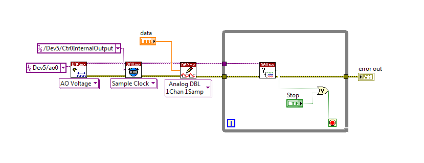
To do this, we will need another counter task that generates a pulse train (see our examples of shipping under material input and output > DAQmx > generating digital pulses > generate dig Pulse Train - Continuous.vi) that stops and starts the user to choose. This can be in another quite VI or controlled by software. We will use this as the task of our output sample clock.
Then, the task of the AO, wire a constant to the sample clock source and select ' DevX/CtrXInternalOutput"based on the counter that you specified in the task of counter. You will need to choose "I/o name of filtration" and check the box that says "include advanced terminals' and right-click of the constant. See picture attached as a reference. In this way, the task of the AO is constantly running, but it generates only actually all data when the meter running task.
Let me know if you have any questions!
Have a great day!
-
I am newbie in Labview... and it is very difficult to find good help and tutorials... it's really disappointing.
I want to find a good simple example of 'the analog output control "...
I found these 'words' somewhere on the internet in the file 'DAQBasic.pdf '.
It is mentioned I need 'VI' easy, but I can't find something like 'Easy VI' in the functions available.
There is far too much info anywhere and there is no structure...
How can I 'the analog output control "?
And please, I want simple examples...
Thank you!
Why spoil things by connecting the key to something?

Your code should be close to what you asked. You want to make sure that there is no case of timeout. I would use the event to change value instead of the key down. At startup, the acquisition of data code run once and then after that, wait key. A couple of different ways to fix this. Simply place the code for the acquisition of data inside the event.
-
Control the analog output in *.vi
Hi you all,.
I have a PCI-6281 with a Bob SCB - 68 in any case, I use two channels of analog output to cross strains of certain instruments. Every time I restart the computer, I reset the tensions Explorer automization and measures. (I'm on measures and Explorer automization > devices and interfaces > NI PCI-6281 dev 1 > test panels... > analog output). Is there a way to have the VI set it each time I run it? THX
Watch the DAQmx Write.vi in the DAQmx palette. Also look in the viewfinder of the example (help-> find examples...) for the analog output DAQmx. There should be a lot of examples that you should be able to disassemble to simply adjust the tensions.
-
Problem of generation of the analog output on PCI-7342
I use for the control of servo motor with encoder Axis 1 of my PCI-7342 feedback
and trying to out of the velocity of the encoder on the analog output of the axis-2 which is currently not used.
For testing purposes, I pulled out a constant 16383 (half of 32767) to the analog output
through load DAC.flx permanently, but there is no voltage on the map of the motion.
I read
http://digital.NI.com/public.nsf/WebSearch/102BE3EEED8A8B0DC1256EDA0059EC47?OpenDocument
and configure my 2 axis to be a stepper motor. I also tried to disable axis - 2. None of them works for me.
Also, I tried to read the value of CAD using reading DAC.flx right after that load DAC.flx is called.
Correctly, the value was shown on the screen. (See the attached figure)
I'm really bad now. Please, please, please help!
Any possible solution is fully appreciated!
Ron Liou
-
How can I check if the counter entry is synchronized with the analog output?
Hello
I'm working on an application for counting photons. I use two channels of analog output on a PCI-6713 card to send a frame model to a set of XY scan mirrors. I then a photon count unit that emits a TTL signal when the photons are detected as a result of this raster analysis. I then use a surfboard USB-6211 to count the edges on this TTL signal.
I have problems that seem due to synchronization problems. I use the sample AO on the PCI-6713 card clock like the door of my meter on the map USB-6211. I use a trigger to start digital to analog output and a trigger of arms for the entrance to counter early. Is there a way to check that the analog output and counter entry of start of operations at the same time and are are synchronized? I basically want to monitor and compare the ao real sample of the PCI-6713 card clock door signal used by the jury of the USB-6211. I was able to export the sample AO clock and watch it on my oscilloscope, but not the signal from the door of the USB-6211.
Thanks for your help,
Brian
Update... It turns out that there is no problem of synchronization between my meter input and the analogue output. There was a difference of impedance when I connected my unit of counting photons to my USB-6211. This caused an error variable count rate. After accouting for this shift, the problem disappeared.
-
Trigger start analogue does not work for the tasks of the analog output
Hello. I wonder - what someone has tested the trigger mode analog start for continuous output voltage-. example of VI under hardware input and output - analog output folder in the Labview.
My camera's SMU-6358, who has two lines APFI and supports analog trigger. Although it is very difficult to find information on the use of analog trigger for analog output of the tasks, what I've learned so far is to connect the interested analog trigger signal (such as an external noise) on both the AI channel which is used as a source of relaxation (ai0 in my case) and a two-channel (APFI0 in my case) APFI.
During the test the example above vi, any level of relaxation that I put (even with 0), the task of output did not work at all. No error message is returned either. Just for your information, I do physical tests, not only the software simulation, so no signal means no signal.
Any help is appreciated!
I have here is that the solutions to this issue, just want to say thank you to all who have helped me on this subject.
Use the analog analog trigger output tasks, make sure that the trigger signal (input HERE) is connected to APFI0. There is no need to connect the trigger even signal to ai0 if you do not want to save the trigger signal. However, if you do not want to save the trigger signal, connect the trigger signal to both ai0 and APFI0 with a signal splitter. In the latter case, the task of the AI shouldn't take the same trigger that the task of the ao. This means that you can start your registration with or without a trigger, while leaving the task of ao wait a trigger of some signal. This is useful in a situation that you only want to generate ao task to a certain trigger event, as when a signal reaches a certain level of sound pressure.
-
Sampling frequency of adjustment for the analog output of sine
Hello
I tried to do something very simple: using an analog output card PCI 6221 to produce a frequency 50 Hz sine curve. For this I used a Vi to create a curve sinus and different screws DAQmx. But I have trouble understanding the principle of virtual channel and I think I do an error of adjustment of the sampling frequency and number of samples: once for the vi, second time sine "DAQmx - synchronization. Can I use the same values for both of these screws?
On my oscilloscope, with frequency = 50 Hz and the sampling frequency = 1 kHz, I get a null signal. Then according to two values, I'm differently evaluated signals. For example, with f = 1 Hz and sr = 10 kHz, a frequency 0.7 Hz sinus.
Make sure that the start for the analog input task occurs after the analog output. By plugging in the wrong thread to an analogue output start task first, and then to the start task, you guarantee that the AI cannot start until after the startup of the AO.
-
cRIO - H bridge using the PWM output and input only encoder control
Hello
I am currently working on a project to control a 230V brushed servo motor using cRIO. The engine drives a linear step and the final project needs to create a control of position of the engine that the user is able to enter a speed, position and control steps to move to this position.
I use a bridge using NOR-9401 and H to power the motor circuit and a PWM output to move the engine. I also have an encoder, quadrature, connected to a NOR-9403 read position and speed. I use the example program of encoder for the NI 9505 - in my application.
There is no voltage or current on the drive circuit sensors so I wouldn't be able to have a closed loop current in this case. The scene release mechanism is such that the position is locked if the motor does not move and I do not need a torque control to keep the engine in place.
To achieve this, I just wouldn't be able to use a single PID VI (probably the FPGA VI express for discrete PID)?
I am not very well versed in the theory of control, and therefore no indication in the common sense would help me a lot.
Thank you very much!

Sexy,.
in general, it is best to use a cascade control loop structure but in principle must also be able to use the output of the control loop of position as an input to the PWM generator. The main disadvantage of this configuration is the current limitation missing. Without current meaning is no longer the only way to protect your engine from drawing too much current to limit to the current maximum output of your diet, or to limit the maximum duty cycle of PWM. Without current information, the last method is quite inaccurate, but better than nothing.
I agree with Mike, you should look in the examples of the 9505 module and use the controller position vi of these examples. This PID controller is optimized for motion control applications and it is implemented in the fixed point arithmetic, offering the best performance on and FPGA.
Kind regards
Jochen Klier
National Instruments
-
Is a PCI-6120 card in a computer with linux useful for the analog output?
We have a PCI-6120, and we want to use in a computer with linux OS, to the analog inputs and analog outputs. I have downloaded the driver NOR-DAQmx Base 3.2 for linux, and in the file README.txt only analog input is mentioned for this Council. It is possible to use this card PCI-6120 in linux, with output and analog input computer?
Best regards
Hey, Gallas,.
This line in the README file simply refers to the PCI-6120 by its more popular, analog input subsystem (given that it is a simultaneous sampling device, the AI is the most commonly used subsystem). But NEITHER-DAQmx for Linux does not have the same limitations NOR-DAQmx base has. In other words, it supports the ability of analog output on the PCI-6120.
Kind regards
Sam
-
an alarm can be set to control an external device using the digital output?
My employer is considering buying a 6210 DAQ and SignalExpress (we currently use a branded DATAQ device).
Looks like I can use the alarm function SignalExpress to define a logic high or low line, controlling a SSR to stop a pump (a non-critical application).
Can I use SignalExpress in this way?
I know LabView can do, but there is no way that the company appears for him.
Thank you.
Hi Jack, this is Paul with Applications Engineering at National Instruments.
SignalExpress supports the functionality you want.
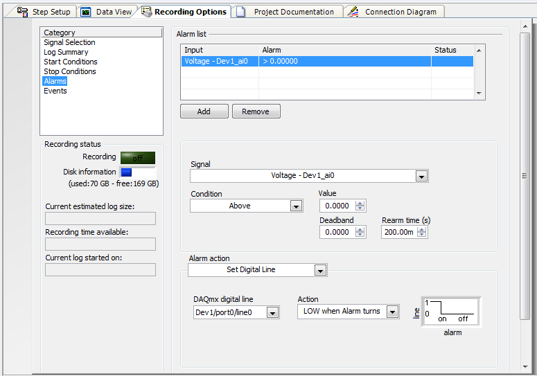
«Once you have configured your signal to acquire you can go to "Save Options" > "Alarms" and then set the alarm conditions, and then choose your Action to alarm as «Defining the digital line»»
I've attached a screenshot of the example of this configuration.
Note here that I put it down when the alarm turned on. You there are other options, including a rocker.
Let us know if you have any other questions!
Paul
-
Configuration of the analog output of the controller PCI-7358
Hello world
I work with the PCI-7358 during a period of time and now I need to configure the output of the controller for a specific purpose. All I have to do is turn on and turn off the output to an analog 5V DC voltage level. I use a UMI-7774 as a breakthrough. I plugged the IO of 5-8 to the UMI axis MOVEMENT and I hope to get the tension off-axis 1 of the UMI CONTROL block. I use DAC.vi to load to turn on and off this PIN on UMI. When I tried the voltage level was 1.5VDC and it fluctuates so I tried to read the voltage on the PIN and she was 3.2Vac. It was said in this DAC.vi of charge help offset values or front torque limits does not affect the level of tension. I can't understand what is to limit the output voltage level. (I tried the 32000 and-32000 for entry this .vi)
If anyone can help urgently, I will be grateful...
Gencer Genç
Hi Roman,
in MAX, you must configure the axis as the stepper motors. You don't have to worry about the type of comment. You can leave this set to "encode". You can configure the engines loop Mode step by step in the tab settings of the Stepper to open loop. But in fact your needs, no matter, if you configure open-loop or closed-loop axis. Any mode stepper will be unmap the CAD of the axis.
In LabVIEW, just use ' configure axis resources "and map of the main output of your axis of stepper output or 'None '. This will also unmap the CAD of the axis. The secondary output must also be mapped to 'None '.
I hope this helps,
Jochen
-
I am acquiring several channels of analog voltage input at the same time, I need to send an output analog two seconds after the start of the entry.
I'm running an experience with accelerometers on a query table.
I start the trigger and the table remains still for two seconds, which allows a reference level for all sensors.
Then the output signal of the VI removes the break in the motor controller.
The speed measured by the encoder is sent to one of the input channels.In this way, our accel and speed data are synchronized.
After it acquired the analog input data out put must be reset to zero.
MULTI.vi I've updated the link above works of VI, I used a property node to solve the problem.
-
To input analog shutdown when the analog output is completed and synchronization
Hello
I'm trying to get my LabVIEW program to send analog output to a computer and read acceleration using the cDAQ-9184. Chassis output that I use is the NI 9263 and the chassis of entry is the NI 9234. I generate a signal of white noise using LabVIEW Express signal generator.
The first problem I have is the synchronization. I had an old VI that has begun to measure the acceleration just about a second after the entry has been given to the machine. I used the LabVIEW tutorial on how to sync the analog input and output, only to discover that it does not work with two different hunts. Then I found another tutorial that shows how to synchronize different frames between them.
The second problem is the cessation of the LabVIEW program. What I want to do is to generate the signal and then simultaneously send and read the input and output analog, respectively. It is because I don't want a phase difference or any shorter signal for a direct comparison. But as soon as the signal is sent to the machine, I want the entry to stop analog playback and then then the LabVIEW program must stop. I want to be able to choose any length of signal to be generated and stop as soon as the entire duration of the signal has been sent to the machine.
I tried 'DAQmx stop', "DAQmx Timer" and 'DAQmx's task made?' and none of them have worked for me. It is also my first time on a forum posting, so I hope I gave enough information. I enclose my VI as well. The VI shows I read an entry for the analog input voltage, but I am only using this to try to get to the work programme.
I'd appreciate any help I could get.
Thanks in advance
Peter
Hi Peter,.
I have some recommendations for you that I think you will get closer to your solution. First of all, I assumed you meant that you had 1 chassis (cDAQ-9184) who had two modules in it (NOR-9263 and NOR-9234). My next steps are based on this assumption, so if it's wrong, please let me know.
For your first question about the synchronization, the code you provided is very close to what you need. You need to do, however, implement architecture master/slave for startup tasks DAQmx functions. To do this, you can add another frame to the flat sequence structure and put the master start task (input voltage) after the start slave (output voltage) task.
To manage your second question and that the program ends at the point where you, the first step is to get rid of all the logic that you use with the local variable of length of time. Rather than use this logic, just wire the node "task performed?" of "is task performed?" operate to stop the loop. This will cause your loop to stop as soon as the signal is sent to the machine.
I have some other recommendations for you that will increase the performance of your program:
(1) rather than writing on file inside the last loop, you can use the DAQmx Configure Logging (PDM) .vi. You will place this VI between DAQmx Timing.vi and DAQmx Start Task.vi to the task of the analog input voltage.
(2) after the last while loop, you want to stop the task and analog outputs as well with another DAQmx stop Task.vi.
(3) rather than using a local variable for the entrance of displacement and wiring it in the DAQmx Write.vi, you can wire directly from the output waveform of the wave to build function node.
That should help you get started in the synchronization of these tasks.
-Alex C.
Technical sales engineer
National Instruments
Maybe you are looking for
-
need to create windows free dvd
Hello my cousin came and took a peek at my new computer and after I left, I realized that my creation of windows dvd was no longer on my computer I thinkhe might have deleted my aciedent and I need that cause I just got a bunch of blank DVDs for my d
-
HP LaserJet 2100 is compatible with Mac OS x 10.7?
I have a HP LaserJet 2100 older and I'm configuring it on a Macbook Pro, I acquired last year. So far I could not find the drivers for OSx 10.7 and ones I've tried have been unsuccessful (10.6). I know there is no available info and drivers for OSx
-
I upgraded from Vista to Windows 7When I try to add the printer manually, I can't select all ports. Plug the printer causes Windows to try to install a driver, but it fails. I suspect it was due to my University Pharos printing system. (It worked whe
-
Problem installing windows 7. It will not go beyond the Welcome screen.
Hello people, Good so I recently bought an SDS and trying to do a clean install of windows 7 but it doesn't let me get past the Welcome screen. Before even the colored balls appear and it just hangs there. I am really frustrated and tried a few thing
-
I have a question, and here is the data for this:Table1:NUM name address date_value1 xxx addr1 date11 xxx addr1 date11 yyy addr2 date21 yyy addr2 date21 zzz addr3 date31 zzz addr3 date3I need to update this tableI need to put the num 1, 1 A and 1 B r