Decimation filter bandwidth
Does anyone have information as to what the BW decimation filter is given at a certain rate of IQ?
For my application, it is more important to vary/control the BW around the carrier. It would be useful to know how 'work backwards' IQ rate since it is the variable that uses the driver.
I'll assume the BW of rate and filter IQ have a fixed relationship regardless of the decimation factor, such as the relationship to the high rate of IQ (low decimation) is the same low IQ (strong decimation)? Is there a "rule" calculation which could make me this info?
For what it's worth, setting speed IQ doesn't seem to be a very useful setting. On the contrary, you are more likely to know the bandwidth you want to capture, and then let simply decimation would produce based on that. Otherwise... If you're not careful (or don't know what you're doing) you might inadvertently filter/decimate and eventually a small piece of BW glancing you think... all this in the name of lower rates of data streaming of the USRP.
The A/D NI with DDCS already seems to do. You specify it given P.C. and SDC configures the decimation based on the nearest whole factor of the A/D sampling rate. There is a handy little table in sheets which shows for a BW given, is that the IQ data resulting rate. I'm basically looking for something similar for the USRP.
Thank you!
---
Brandon
This could be a subtle understanding, I won RF by thet rate bu IQ equipment is ultimately limiting your maximum bandwidth. How much this bandwidth is usable depends on a device. (True for the acquisition and generation)
In an ideal world, your IQ rate "would be tantamount to your bandwidth" (acquisition). This is the general rule. If you take a FFT on a number of samples at a rate of 10 MSa/s, you will find yourself with a frequency which extends MHz - 5 to + 5 MHz. If your signal uses this entire range of 10 MHz is not implied, but you would not be able to fully acquire a signal with a bandwidth greater than 10 MHz for sure.
The USRP has specific IQ rates it supports, so I season always re-reading the IQ rate under duress. If you need to change your filter specifications or need more flexibility just decimate and only filter process, think I woud suggest to implement a filter software - your choice opens considerably as well as being able to choose a butterworth on a chebyshev and specifying the order of the filter, etc..
I also suggest reading this article as well from the GNU Radio page, it has a little more depth and background.
Tags: NI Products
Similar Questions
-
Good application of a filter of 50 Hz
Hello
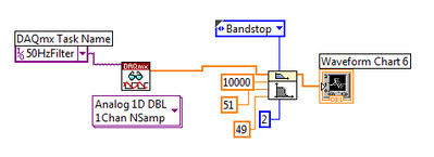
I need to apply a filter of 50 Hz to an acquisition of signals DAQ (noise for testing).
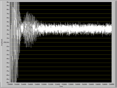
When I apply the filter, the resulting signal has enormous oscillations in the first part of the signal acquired (as see you in "Filter output.png"), after these oscillations, the signal becomes filtered as it should.
I tried to change the sampling frequency, the frequency of signal acquisition and all other settings, but I can't get rid of these oscillations.
What Miss me?
In "Diagram.png", you see the pattern of the filter.
The signal is acquired at 10 k rates and includes 30 k points.
I have some experience with Labview, but I've never used its filters.
Thanks for the help
Your image resolution is a bit low to be sure, but it seems that you have a significant lag in the data. A mismatch can lead the transient response of the filter. With a filter bandwidth, which can produce an oscillating reaction.
With your entry of noise you get very little energy in the band stop filter so it can be difficult to see the effect. When I simulate your signal with offset of the hard shoulder is almost impossible to detect. The noise in each tray is approximately 60 dB below the offset and the stopband attenuation is about the same. Without the offset the stopband is detectable (visually on a graph) about a quarter of the time. With 300000 samples, it is almost always visible with or without the offset. See the image below.
This is the spectrum of random noise with shift amplitude of 5 times and 300000 samples.
Usually interpreted restrictively the frequency response of a filter, more transient response.
Lynn
-
Unable to load the shared library LVASPT_WA.*
Hello
I have a hope that easy to fix the error: I want to use the function "WA Detrend' to the signal processing tool advanced in a real-time application running on a cRio 9030. When I try to run the VI I get the following error:
...
Deployment NI_AdvSigProcWA.lvlib:WA decimation Filter.vi
NI_AdvSigProcWA.lvlib:WA decimation Filter.vi loaded with errors on the target and was closed.
LabVIEW: Unable to load the shared library LVASPT_WA.* ptDecimationFilterH:C. make sure that the library is present on the target of RT. Either MAX allows you to install software from OR or FTP to transfer custom RT target libraries.
...
I reinstalled signals Advanced processing toolkit and linked things 'add new software' MAX, but the error persists.
A picture of what the system looks like to the MAX is attached.
Also, I Fund this post:
could someone tell me what he means by "Please check the installation of the custom software all mode '?
Can you telll me what I am doing wrong?
Thank you very much in advance!
I ran your situation in R & D, and the problem seems to be as a result of Advanced Signal Processing Toolkit is not not compatible on the x 64 under Linux RT OS in the 9030. The product page could be clearer on this gap. I am currently a web application to get this fixed!
Best,
David
-
NEITHER USB-6251 antialiasing filters
Hello
NI USB-6251 and I have to use the maximum sampling frequency 1250 Khz how I could put anti-aliasing filters? help please
I have also the NI 9234 to receive a signal of the 4 channels at sampling rate 50 khz for each channel should I put anti-aliasing filters in this case or not?
Thank youThe USB-6251 casing served only at this rate on a single channel. If you use several channels the total maximum rate is 1 MECH. / s. You must install an anti-aliasing filter before entering the device. Filter bandwidth could be as low as 625 kHz (Nyquist frequency) or a little more depending on the noise or interference that accompanies your signal.
The NI 9234 is a built-in anti-aliasing filter. Your sampling rate is slightly less than the maximum sampling rate, you should not have any other filter. If you have an extreme case of a strong interference signal just outside the bandwidth of the signal, a special filter could be useful
Lynn
-
Help for the reconciliation of table. Average cost
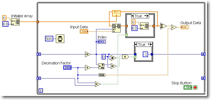
So this is my attempt to imitate a function block that we use in our standard converter software - "Decimation filter" which is nothing more than a running average / mobile. The sample size is adjustable to execution of 2 to 64 samples (decimation factor). I saw many topics on this and used to average around 4 large samples shift registers - but I wanted to be able to change the sample size without recompiling. I'm new to LV, there is likely a lot of better ways to do this.
I would like to have answered is linked to clear the table, if the decimation factor is set to a lower number than the last time that the loop executed. (The uppercase - false statement is wired directly by)
The math in the shift register: creates an array index that cycles from 0 to (decimation Factor-1). The index is then used to fill elements in the table (the rest being zeros). When the decimation factor decreases, I need zero external element in (former decimation factor - 1) (new decimation Factor-1) positions. So I tried various things, but the only thing that seems to work, it's the re - initialize the array. I think it's less than optimal.
I tried:
(1) leaving the tunnel of continuous wire output for the real deal and selecting the option 'use default if unwired' - thinking I'd get a table of 64 elements, of zeros. Doesn't seem to work.
(2) a constant matrix cable tunnel exit if this value is true. When I followed him, after a decline in decimation factor - the probe seems to indicate an array of elements, not 64 No. And I do not see how to specify the size of the array of constant matrix.
If I use this in my application it will run on a target of cRIO.
Any help much appreciated.
You already have your initialized table, why not use it? Wire your table initialized via if this value is TRUE. Or better yet, use Select? function.

-
decimation (decimation.vi there a pass filter down?)
Hello
I have a question about the decimation (decimation (continuous) .vi) function in labview. Has a low pass filter to take care of the aliasing, if so it's a zero-phase filter. Basically, I'm looking for something that can decimate 20 kHz signals sampled at 5 kHz.
Thank you
Kitenge
Depends on your version of LabVIEW and installed toolboxes.
The Digital Filter Design Toolkit has a decimation VI which includes an AA LP filter. Open the help of LabVIEW and search "decimation" and "filter" to see what tools are available.
-
FPGA Butterworth filter - why conversions to decimal fixed?
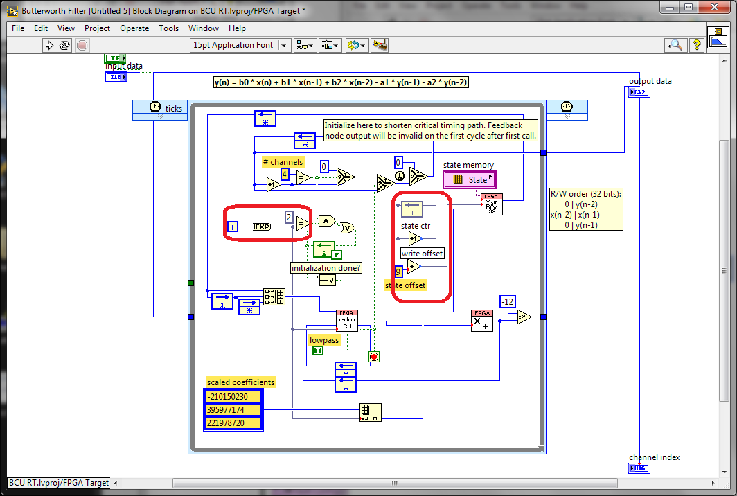
I was looking through the screw FPGA Butterworth filter Express and stumbled on this code (after conversion the Express VI into a Subvi and then by opening the front panel):
What is happening with the conversion to decimal fixed values that look like they must be integers (in the red boxes)? Why these conversions would be useful?
Here is the micro-optimisations to help the synthesis tools to minimize the number of bits used in these code paths. The iteration Terminal is 32 bits wide and also involves a logic to do in the face of what is happening when the maximum value is reached. We have seen some benefits from the reduction of this path to the minimum width required both that which is written. I think it is probably still the case since the compiler usually does not know how many times a given line will run with a dynamic stop like this condition.
The optimization of the meter width is similar, taking advantage of the fact that we know that we have limited storage space to use circular buffers power-of-2 size. Using the exact number of bits of the address allows us to implement a counter of reversal with no additional logic. otherwise, we would need to check the value, and add a mux (Select) to reset the counter when it reaches the maximum value.
Synthesis tools usually do a good job of optimizing the unused bits, but here are two cases where we can help them by being more explicit about what we really need.
-
Point decimal answers into question every choice filter
I ran into a question of answers with decimal points, appearing in the filter all the choices, even if the properties of column for the criteria indicate 0 decimal places. The results back to the criteria does not return a decimal that is the goal. The column is defined as a DOUBLE in the rdp protocol being the column of database data type number with a length of 10 - NUMBER (10). The generated response query does not return the decimal points in SQL * more. Has anyone came across this and have a work around?According to me, can you check the fx from the command prompt and to cast as an int and then check, let me know if you continue to see decimal results.
-
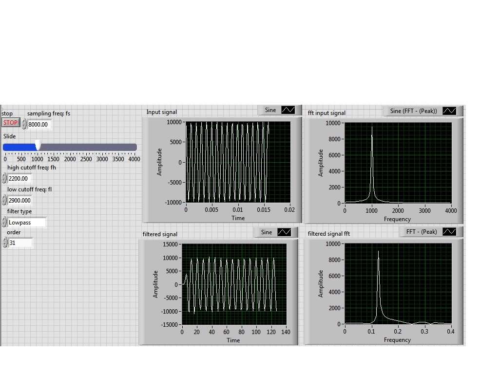
I'm simulating a sine wave at approximately 1000 Hz (I'm variable according to the frequency with a slider), I would like to pass this signal by a lowpass filter (butterworth) with a high frequency of 2200 Hz cuttoff and a low pass to 2900 Hz frequency. However, the output after the filter frequency seems to be lower in the order of a thousand. the output frequency is about 0.1 Hz.
Y at - it someone who can guide me please to solve this problem, I tried different filters and I'm still having this problem, it would be incorrect sampling?
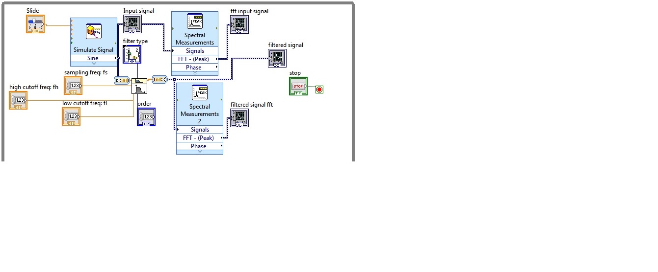
I enclose the block diagram and the front panel
Because you use express screws and the type of dynamic data...
You convert the signal of DDT (which contains the clock information) in a table DBL to perform filtering. Take it a DBL array (which contains no data of timing) and converted it into a DDT (which now contains no data timing). That's why when you try to view and analyze it you have lost all the data timing (frequency).
If you were to exit table DBL of your filter and build a wave form and provide the dt to the waveform of the sampling frequency control, then it will work.
Better yet, ditch the DDT and use waveforms from the beginning

-
Counters of artifacts of high rates of decimation filtering
Hello
I have problems with a report filter high decimation of artifacts in my data.
I use Digital Filter Design NStage MRate filter Design VI to create you a filter step achieve a ratio of decimation of 2000. The first step is a CIC. Both are the TREE. The decimation ratio first step is 500. The other two are 2. My incoming data rate is between 1 and 10 MECH. / s.
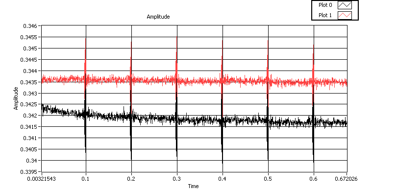
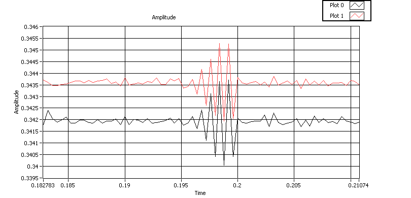
I'm acquiring a few seconds of data in blocks 200 ksps, and I'm filtering their block by block. I get artifacts at the borders between the blocks, as described below in two different zoom levels:
When you implement this filter, get the best results using the MRate Nstage DFD filtering to block VI with the symmetrical extension type. I think that it is supposed to avoid artifacts at the extremes of field.
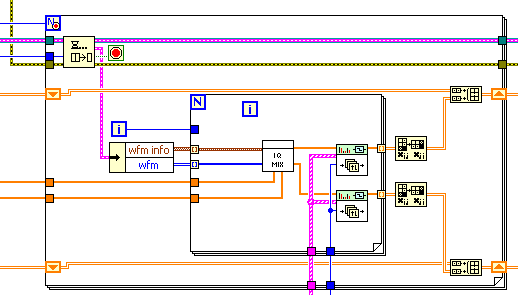
My application is lower. Another loop acquires the data blocks, and stores them in the queue. This loop treats each data block. The reason for the inside of the loop is because data are acquired from two channels simultaneously, make the waveform output a table 2 x 200000. The vi 'IQ Mix' is a mixture a wave of frequency equivalent with the data to convert it to focus on the DC I and Q signals.
Anyone who deals with this problem before? It strengthens with the highest ratio of decimation and lower bandwidth.
Cody,
Thanks for the offer, but I think that I traced this problem down.
Number 1 has been that if I want to deal with continuous data, my mix waves must be continuous. I mixed a same wave with each block. I did the phase of my wave continuous mixing from block to block, and which removed a lot of artifacts.
Number 2 was that I need to use the right filter treatment VI. Above, I use the VI for one-piece, non-continuous treatment.
Number 3 was when using the continuous processing VI, I need to make sure you use a separate VI for each channel instance, I want to deal with. This means that I can't use a loop for looping through the channels. A non-parallelisee loop for use the same instance for all iterations. Paralleled A for loop is not compatible with that iteration uses what instance.
I'm not completely out of the woods yet, however. I always have problems with the first block of data, that I proceeded. I think it's a quite different problem for a separate thread, though.
-
Message error "arrested -"filter"has failed."
After upgrading to Mac OS Sierra, when you attempt to send a test print my Epson Stylus Photo 2200, I get the message error "stop -"filter"failure" in my print queue.

I have left clicked on the printer-> error log menu item, and I have the following in the error log.
E [27/Sep / 2016:10:04:40-0500] [Job 3] Job is stopped due to errors in filter; For more details, see the error_log file.
D [27/Sep / 2016:10:04:40-0500] [Job [3] the following messages have been saved since 10:04:38 to 10:04:40
D [27/Sep / 2016:10:04:40-0500] banner of start-up [Job 3] adding page 'none '.
D [27/Sep / 2016:10:04:40-0500] [Job 3] queued on the "EPSON_Stylus_Photo_2200" by "derekberube".
D [27/Sep / 2016:10:04:40-0500] file [Job 3] seized automatic...
D [27/Sep / 2016:10:04:40-0500] [Job 3] request file type is application / vnd.cups - banner.
D [27/Sep / 2016:10:04:40-0500] [Job 3] file of type application / vnd.cups - banner in queue 'derekberube '.
D [27/Sep / 2016:10:04:40-0500] [Job 3] end banner add page 'none '.
D [27/Sep / 2016:10:04:40-0500] [Job 3] time to processing = 1474988678
D [27/Sep / 2016:10:04:40-0500] [Job 3] 3 filters for task:
D [27/Sep / 2016:10:04:40-0500] [Job 3] cgbannertopdf (application / vnd.cups - banner to application/pdf, cost 33)
D [27/Sep / 2016:10:04:40-0500] [Job 3] cgpdftoraster (application/pdf in the application / vnd.cups - raster, cost 100)
D [27/Sep / 2016:10:04:40-0500] [Job 3] /Library/Printers/EPSON/InkjetPrinter2/Filter/rastertoescpII.app/Contents/MacOS /rastertoescpII (application / vnd.cups - raster to printer/EPSON_Stylus_Photo_2200, 0 cost)
D [27/Sep / 2016:10:04:40-0500] [Job 3] job-sheets = none, none
D [27/Sep / 2016:10:04:40-0500] [Job 3] argv [0] = "EPSON_Stylus_Photo_2200".
D [27/Sep / 2016:10:04:40-0500] [Job 3] argv [1] = '3 '.
D [27/Sep / 2016:10:04:40-0500] [Job 3] argv [2] = "derekberube".
D [27/Sep / 2016:10:04:40-0500] [Job 3] argv [3] = "testprint.
D [27/Sep / 2016:10:04:40-0500] [Job 3] argv [4] = "1".
D [27/Sep / 2016:10:04:40-0500] [Job 3] argv [5] = "AP_ColorMatchingMode = AP_VendorColorMatching AP_D_InputSlot = nocollate com.apple.print.DocumentTicket.PMSpoolFormat=application/pdf com.apple.print.JobInfo.PMJobName = testprint com.apple.print.PrinterInfo.PMColorDeviceID... n. = 23775 com.apple.print.PrintSettings.PMCopies... n = 1 com.apple.print.PrintSettings.PMCopyCollate... b. com.apple.print.PrintSettings.PMFirstPage... n = 1 com.apple.print.PrintSettings.PMLastPage... n = 2147483647 com.apple.print.PrintSettings.PMPageRange... a.0... n = 1 com.apple.print.PrintSettings.PMPageRange... a.1... n. = 2147483647 fit-to-page media = letter requested by pserrorhandler = standard job-uuid=urn:uuid:8781dff0-21e9-31ef-5b09-534d193452be job-originating-name of host = localhost to-date-time-create = date-time-to-processing = time-to-creation" time processing 1474988678 = 1474988678 = document-name-supplied testprint PageSize = letter»
D [27/Sep / 2016:10:04:40-0500] [Job 3] argv [6] = "/ private/var/spool/cups/d00003-001.
D [27/Sep / 2016:10:04:40-0500] [Job 3] envp [0] = "< CFProcessPath >".
D [27/Sep / 2016:10:04:40-0500] [Job 3] envp [1] = "CUPS_CACHEDIR = / private/var/spool/cups/cache '.
D [27/Sep / 2016:10:04:40-0500] [Job 3] envp [2] = "CUPS_DATADIR = / usr/share/cups.
D [27/Sep / 2016:10:04:40-0500] [Job 3] envp [3] = "CUPS_DOCROOT = / usr/share/doc/cups.
D [27/Sep / 2016:10:04:40-0500] [Job 3] envp [4] = "CUPS_FONTPATH = / usr/share/cups/fonts.
D [27/Sep / 2016:10:04:40-0500] [Job 3] envp [5] = "CUPS_REQUESTROOT = / private/var/spool/cups.
D [27/Sep / 2016:10:04:40-0500] [Job 3] envp [6] = "CUPS_SERVERBIN = / usr/libexec/cups.
D [27/Sep / 2016:10:04:40-0500] [Job 3] envp [7] = "CUPS_SERVERROOT = / private/etc/cups.
D [27/Sep / 2016:10:04:40-0500] [Job 3] envp [8] = "CUPS_STATEDIR = / private/etc/cups.
D [27/Sep / 2016:10:04:40-0500] [Job 3] envp [9] = "HOST = / private/var/spool/cups/tmp".
D [27/Sep / 2016:10:04:40-0500] [Job 3] envp [10] = "" PATH = / usr/libexec/cups/filter: / usr/bin: / usr/sbin: / bin: / usr/bin ""
D [27/Sep / 2016:10:04:40-0500] [Job 3] envp [11] = "[email protected]".
"D [27/Sep / 2016:10:04:40-0500] [Job 3] envp[12]="SOFTWARE=CUPS/2.2.0 ".
D [27/Sep / 2016:10:04:40-0500] [Job 3] envp [13] = ' TMPDIR = / private/var/spool/cups/tmp ".
D [27/Sep / 2016:10:04:40-0500] [Job 3] envp [14] = "USER = root"
D [27/Sep / 2016:10:04:40-0500] [Job 3] envp [15] = "CUPS_MAX_MESSAGE = 2047"
D [27/Sep / 2016:10:04:40-0500] [Job 3] envp [16] = ' CUPS_SERVER = / private/var/run/cupsd.
D [27/Sep / 2016:10:04:40-0500] [Job 3] envp [17] = "CUPS_ENCRYPTION = IfRequested"
D [27/Sep / 2016:10:04:40-0500] [Job 3] envp [18] = 'IPP_PORT = 631'
D [27/Sep / 2016:10:04:40-0500] [Job 3] envp [19] = "CHARSET = utf-8"
D [27/Sep / 2016:10:04:40-0500] [Job 3] envp [20] = "LANG = fr_FR. UTF - 8"
D [27/Sep / 2016:10:04:40-0500] [Job 3] envp [21] = "APPLE_LANGUAGE = en - en"
"D [27/Sep / 2016:10:04:40-0500] [Job 3] envp[22]="PPD=/private/etc/cups/ppd/EPSON_Stylus_Photo_2200.ppd ".
D [27/Sep / 2016:10:04:40-0500] [Job 3] envp [23] = "RIP_MAX_CACHE = 128 m"
D [27/Sep / 2016:10:04:40-0500] [Job 3] envp [24] = "' CONTENT_TYPE = application / vnd.cups - banner" "
D [27/Sep / 2016:10:04:40-0500] [Job 3] envp [25] = "DEVICE_URI = 0 usb://EPSON/Stylus%20Photo%202200?serial=L5602021107061925"
D [27/Sep / 2016:10:04:40-0500] [Job 3] envp [26] = "PRINTER_INFO = EPSON Stylus Photo 2200"
D [27/Sep / 2016:10:04:40-0500] [Job 3] envp [27] = "PRINTER_LOCATION = MacBook Pro Derek Berube\"
D [27/Sep / 2016:10:04:40-0500] [Job 3] envp [28] = "PRINTER is EPSON_Stylus_Photo_2200"
D [27/Sep / 2016:10:04:40-0500] [Job 3] envp [29] = "PRINTER_STATE_REASONS = none"
D [27/Sep / 2016:10:04:40-0500] [Job 3] envp [30] = "CUPS_FILETYPE = document"
D [27/Sep / 2016:10:04:40-0500] [Job 3] envp [31] = "" FINAL_CONTENT_TYPE = vnd.cups - raster/application ""
D [27/Sep / 2016:10:04:40-0500] [Job 3] envp [32] = "AUTH_I."
D [27/Sep / 2016:10:04:40-0500] [Job 3] Started filter/usr/libexec/cups/filter/cgbannertopdf (PID 2075)
D [27/Sep / 2016:10:04:40-0500] [Job 3] Started filter /Library/Printers/EPSON/InkjetPrinter2/Filter/pdftopdf2.app/Contents/MacOS/pdft opdf2 (PID 2076)
D [27/Sep / 2016:10:04:40-0500] [Job 3] Started filter/usr/libexec/cups/filter/cgpdftoraster (PID 2077)
D [27/Sep / 2016:10:04:40-0500] [Job 3] Started filter /Library/Printers/EPSON/InkjetPrinter2/Filter/rastertoescpII.app/Contents/MacOS /rastertoescpII (PID 2078)
D [27/Sep / 2016:10:04:40-0500] [Job 3] Started backend/usr/libexec/cups/backend/usb (PID 2079)
"D [27/Sep / 2016:10:04:40-0500] [Job 3] Message catalog filename is \"/System/Library/Frameworks/ApplicationServices.framework/Versions/A/Framework s/PrintCore.framework/Versions/A/Resources/English.lproj/cups_apple.strings\.
D [27/Sep / 2016:10:04:40-0500] [Job 3] load_banner(filename=\"/private/var/spool/cups/d00003-001\")
D [27/Sep / 2016:10:04:40-0500] [Job 3] usb: AppleLanguages =-"en - US\".
D [27/Sep / 2016:10:04:40-0500] [Job 3] STATE: + connection-device
D [27/Sep / 2016:10:04:40-0500] [Job 3] looking for \'EPSON Stylus Photo 2200\'
D [27/Sep / 2016:10:04:40-0500] [Job 3] open connection
D [27/Sep / 2016:10:04:40-0500] [Job 3] PID 2078 (/Library/Printers/EPSON/InkjetPrinter2/Filter/rastertoescpII.app/Contents/MacO S/rastertoescpII) was arrested with the 206 State (output Interface queue is full)
D [27/Sep / 2016:10:04:40-0500] [Job 3] Tip: try to set the LogLevel "debug" to learn more.
D [27/Sep / 2016:10:04:40-0500] [Job 3] Page = 612 x 792; 9.40 at 603-783
D [27/Sep / 2016:10:04:40-0500] [Job 3] directory ' / Library/Printers/EPSON/CIOSupport/EPSONUSBPrintClass.plugin ' permissions OK (040755/uid = 0/gid = 80).
D [27/Sep / 2016:10:04:40-0500] [Job 3] directory ' / System/Library/Printers/Libraries/USBGenericPrintingClass.plugin ' permissions OK (040755/uid = 0/gid = 0).
D [27/Sep / 2016:10:04:40-0500] [Job 3] load_classdriver(/System/Library/Printers/Libraries/USBGenericPrintingClass.plu gin) (kr:0 x 00000000)
D [27/Sep / 2016:10:04:40-0500] [Job 3] load_classdriver(/Library/Printers/EPSON/CIOSupport/EPSONUSBPrintClass.plugin) (kr:0 x 00000000)
"D [27/Sep / 2016:10:04:40-0500] [Job 3] cgpdftoraster: copy to temp \"/private/var/spool/cups/tmp/0081d57f93b5a\ print file '.
D [27/Sep / 2016:10:04:40-0500] [Job 3] STATE:-connecting-to-device
D [27/Sep / 2016:10:04:40-0500] [Job 3] sending data to the printer.
D [27/Sep / 2016:10:04:40-0500] [Job 3] sent 0 bytes...
D [27/Sep / 2016:10:04:40-0500] [Job 3] STATE: + cups-wait-for-work-over
D [27/Sep / 2016:10:04:40-0500] [Job 3] align for banner 1.
D [27/Sep / 2016:10:04:40-0500] [Job 3] PID 2075 (/ usr/libexec/cups/filter/cgbannertopdf) came out without error.
D [27/Sep / 2016:10:04:40-0500] [Job 3] PID 2076 (/Library/Printers/EPSON/InkjetPrinter2/Filter/pdftopdf2.app/Contents/MacOS/pdf topdf2) came out without error.
D [27/Sep / 2016:10:04:40-0500] [Job 3] cgpdftoraster: \"/private/var/spool/cups/tmp/0081d57f93b5a\"has 1 pages.
D [27/Sep / 2016:10:04:40-0500] [Job 3] cgpdftoraster: open \"/private/etc/cups/ppd/EPSON_Stylus_Photo_2200.ppd\ file PPD «...»
D [27/Sep / 2016:10:04:40-0500] [Job 3] cgpdftoraster: PreferredRotation = - 90
D [27/Sep / 2016:10:04:40-0500] [Job 3] cupsPageSize = [612 792], cupsImagingBBox = [9 40 603 783]
D [27/Sep / 2016:10:04:40-0500] [Job 3] cgpdftoraster: width = 612, length = 792, high = 9, low = 40, left = 9, right = 9
D [27/Sep / 2016:10:04:40-0500] [Job 3] cupsWidth = 2970, cupsHeight = 3715
D [27/Sep / 2016:10:04:40-0500] [Job 3] cgpdftoraster: languageLevel = 3, mediaBox.size.width = 612, mediaBox.size.height = 792
D [27/Sep / 2016:10:04:40-0500] [Job 3] cgpdftoraster: colorspace = 1, bitsPerColor = 8
D [27/Sep / 2016:10:04:40-0500] [Job 3] cgpdftoraster: the seller matching mode is turned on and the requested transfer color space is sRGB.
D [27/Sep / 2016:10:04:40-0500] [Job 3] cgpdftoraster: skipBytesPerRow = 8
D [27/Sep / 2016:10:04:40-0500] [Job 3] cgpdftoraster: bandwidth = 2970, bytesPerRow = 11888, band height = 3715, height = 3715
D [27/Sep / 2016:10:04:40-0500] [Job 3] cgpdftoraster: width of the frame = 2970, height = 3715 bitsPerComponent is 8, bitsPerPixel = 32 bytesPerRow = 11888, bitmapInfo = 5, resolution = (360.000000, 360.000000)
D [27/Sep / 2016:10:04:40-0500] [Job 3] HWResolution = [360 360]
D [27/Sep / 2016:10:04:40-0500] [Job 3] ImagingBoundingBox = [9 40 603 783]
D [27/Sep / 2016:10:04:40-0500] [Job 3] margins = [9-40]
D [27/Sep / 2016:10:04:40-0500] [Job 3] PageSize = [612 792]
D [27/Sep / 2016:10:04:40-0500] [Job 3] cupsWidth = 2970
D [27/Sep / 2016:10:04:40-0500] [Job 3] cupsHeight = 3715
D [27/Sep / 2016:10:04:40-0500] [Job 3] cupsBitsPerColor = 8
D [27/Sep / 2016:10:04:40-0500] [Job 3] cupsBitsPerPixel = 24
D [27/Sep / 2016:10:04:40-0500] [Job 3] cupsBytesPerLine = 8910
D [27/Sep / 2016:10:04:40-0500] [Job 3] cgpdftoraster: rasterWriteHeader: unable to write the header streams raster: Broken pipe
D [27/Sep / 2016:10:04:40-0500] [Job 3] cgpdftoraster: bytes written for the side 1 = 0, err = 5
D [27/Sep / 2016:10:04:40-0500] [Job 3] PID 2077 (/ usr/libexec/cups/filter/cgpdftoraster) came out without error.
D [27/Sep / 2016:10:04:40-0500] [Job 3] waiting for read thread exits...
D [27/Sep / 2016:10:04:40-0500] [Job 3] PID 2079 (/ usr/libexec/cups/backend/usb) came out without error.
D [27/Sep / 2016:10:04:40-0500] [Job 3] end of messages
D [27/Sep / 2016:10:04:40-0500] [Job 3] printer - state = 3 (idle)
D [27/Sep / 2016:10:04:40-0500] [Job 3] printer-State-message = "Sending data to printer."
D [27/Sep / 2016:10:04:40-0500] [Job 3] - printer-motivation = none
Line 66 # in the above seems to indicate the rastertoescpII utility failed with a status code of 256 and the error message "output Interface queue is full.
Troubleshooting steps
To try to solve this problem, I followed the steps described in the article «problems of printer on your Mac» I have reset the printing system and it does not work. I have also unplugged the printer, deleted the contents of the folder/library/printers/and then plugged the printer into.
You will need to check with Epson to see if there is a new driver for your device compatible with macOS Sierra. The old drivers are not compatible. Even with the new driver, some people state that the error is not fixed :-( YMMV.
-
I am trying to perform a decimation operation into the fpga by capturing a LPF exits
at a slower pace than the filter. My filter running at 80 MHz and I am trying to capture the
data filter to 40 MHz (downsampling by 2) to complete the extermination operation.
The filter is in a single cycle timed loop and I'm looking data that comes from that
filter using probes that are in the loop slower (running at 40 MHz). What I see is that the
slower loop does not appear to be updated at the rate of duty. I expected to see all other
sample of the loop of 80 MHz enter the loop of 40 MHz. Instead, I see a value which seems to be
held for several cycles.
I use a local variable to pass the data between the 2 loops. The data appear to be
scaling. For example, leaving the 80 MHz loop I see a value-13.9375 on the local variable;
I read this same variable in the loop of 40 MHz, it seems to be - 13.312.
I have attached the vi where it is useful.
Kind regards
Chuck
I did have the chance to look at your code, but a few things come to mind which can help. I think that you run the code in emulation (running on the development computer) mode to debug. This is a useful feature to find logical errors, but there is no guarantee of timing in this mode. Therefore, we can assume that the 80 MHz loop runs 2 iterations for each 1 iteration of the loop of 40 MHz. Which could explain what you see. I assume that you are running in emulation mode, because you have a constant-1 as a starter on the FIFO nodes. This is not a valid parameter when you use the FIFO inside a loop timed cycle unique (SCTL). You need to wire a constant 0 FIFO timeout inside. The reason is that the SCTL running each iteration within the clock cycle in the material. There cannot be any code that blocks within the SCTL. I know a code from your code generation error if you actually tried to compile. I know that this isn't very useful information in your question, but thought you should know. Another tip is that there is a functionon rational resampling the FPGA palette. You can find it under programming > FPGA math and analysis > rational Resampler. It can be configured for an entire decimation by setting L 1 and M 2. He'll probably use more resources than your current implementation, but be quite simple.
-
How to reduce the use of bandwidth LAN?
I want to design a relay system using two USRP of NI USRP 2922 with sample rates even as LTE standard. But there is limitation in the use of bandwidth of 1 Gbps LAN.
I don't think you should achieve the full rate on a USRP without a link dedicated to the PC. The protocol used is UDP between USPR and PC which can be disruped by the latency of the network and cause packets to arrive out of order or get lost. You should also assume that, due to the effects of edge filter only 80% of the specified bandwidth is usable. (20 MHz of bandwdith requires a rate of IQ of 25. MECH / s) It takes a fast PC with a very high quality (we use intel) NIC to get there. But you will need to use the driver for the NIC card manufactuer and maximize the RX and TX buffers. So far, I realized only on desktop computers and mobile no. I also would assume the package of 20% load, so on a 1 Gbps link, I would not expect to exceed the 800 MB/s.
25 MS/s x (16 bit 16 bit I + q) = 800 MB/s
You can also, in the pilot, 8-bit mode which will halve your dynamic range, but also the data rate.
For a system like yours, you can consider to put a PC next to each usrp and install 2 network cards in each PC. You will add the latency, but the additional computer will give you buffer against congestion and network problems. In addition, relay is not a 'constant' streaming activity... only the RX is constant. For TX, you can use the approach of gusts of transmission.
Erik
-
Low-pass filter before the NI 5112
Hello
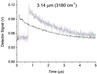
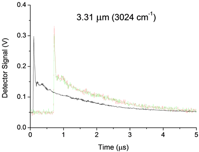
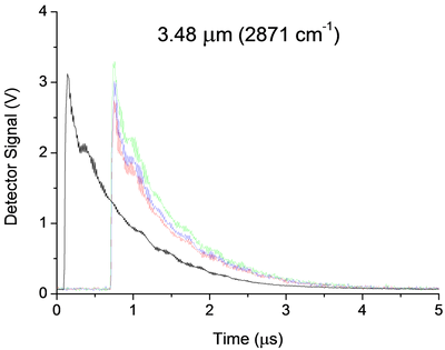
I currently use a 5112 AND measure the signal of an infrared detector in an experience of ring to the bottom of the cavity. Below are three examples of signals. My main question is how I can implement a low pass filter, passive preference, before my 5112 OR undistorted extremely my signal due to the impedance mismatch. Now a few details:
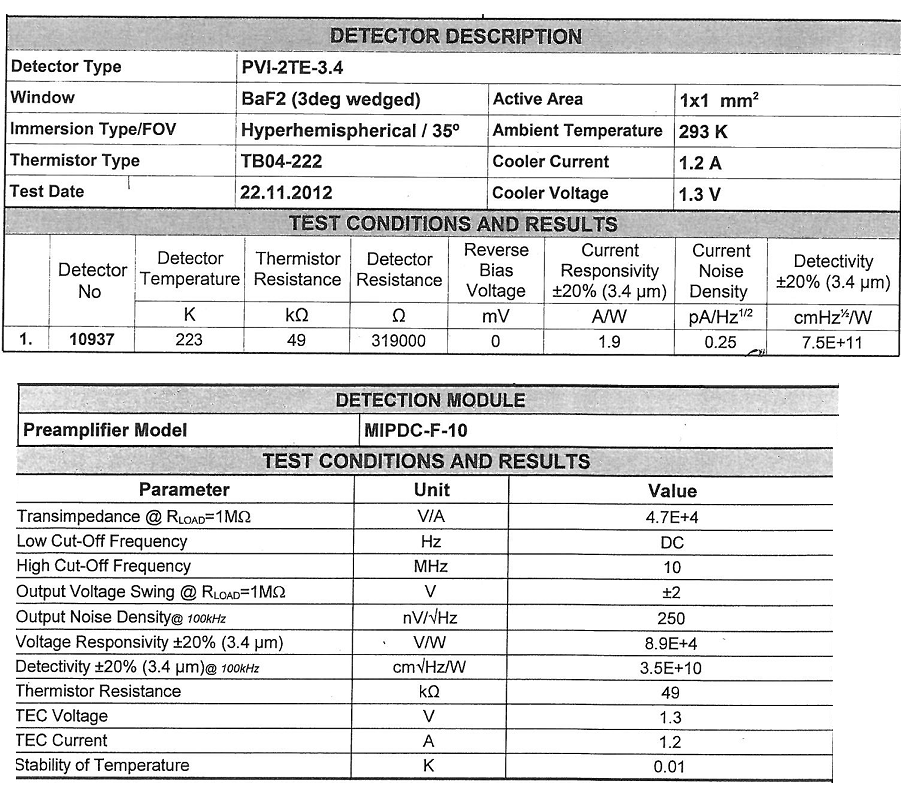
Some unique captures for each wavelength are shown in color, while average 25 pulses appears offset in black. The range and offset are chosen in each case in order to minimize the noise of "scanning". In the case of 3.14um, the noise that you see is about 25 times noise from scanning. They were taken without the limitation of BW and 100 ms/s mode.
The detector (Vigo MIPDC-F-10) has a bandwidth of 10 MHz. I think it is a low impedance and is intended to be harnessed with 50Ohms, however its documentation confuses me, and I'm waiting for a definitive answer from the provider. 2.4 part of the manual says 50Ohms recommended, however the Datasheet and our map calibration (below) seem to suggest 1 MOhm is recommended!
There are a few strange oscillations with a period of almost 180ns in our signal that I thought were due to the impedance mismatch existed in the system before I changed it:
-Detector
-1 metre 50 Ohm SMC Cable BNC (RG-174)
-Inline BNC connector
-meter 5, 75 Ohm BNC to BNC cable
-Digitizer, DC, no BW limit, 100 ms/s, 1MOhm | 30pF
When I saw this configuration, I knew something wasn't right and I even he modeled in LTSpice and he showed the same period of oscillations. But now, the Setup is:
-Detector
-1 metre 50 Ohm SMC Cable BNC (RG-174)
-BW digitizer, DC, limit, 100 ms/s, 50 Ohm
And we still have oscillations, even if the period seems to have changed to 320ns all about. These oscillations, which remain are 99%, probably due to our drop-down ring cavity experiment, however if anyone has recommendations on possible causes or ways I can confirm it is not because of my chain of detection they would be more than welcome!
Now, the main question. Between the 50 Ohm 1 meter cable and the scanner I would insert a low pass filter. The BW limit has helped reduce the noise, but it can certainly still be further reduced without any lose to our signal. That's because we cut the beginning of the signal and then measure just the the decay time, which is relatively long and smooth (1 to 2 times 1/e US). Thus, in the future I may even want to try to eliminate the oscillations 320ns, but I'm afraid that this much filtering will distort the signal too. Therefore, for the immediate future I'm just looking to 'replace' the filter BW 20 MHz, with something like 1 or 5 MHz.
Of course, I would disable the BW limit on the digitizer to avoid additional confusion, but nevertheless, I'm not sure how to approach the problem. Usually I do a lot of research and try different solutions. However, I don't have access to all components to this work, so everything should be ordered, and I don't have a lot of time to experiment. Ferrites seem like a possible solution, however not sure how effective they are at this low frequency or the way they work with coaxial cables. I know that the filter passes low RC base, but the 50Ohms (or 1MOhm | 30 pF if I change it) seem to make it impossible. I guess an op-amp based one might work, however the large input impedance is the impedance of coaxial cable... etc...
All of the recommendations of the technique or red resources wort would be welcome. Thanks for your time.
A possible way to separate your artifacts electric and the cavity is relatively simple. You take the data at three wavelengths. For each of them, make a simple exponential decay (for example exponential Fit.vi) adjustment to your data, then subtract this signal. You should have something that oscillates on an average. Compare the residual signals for all three wavelengths, either visually or with something like a power spectrum. Anything in the three is probably the electronic (and you could possibly model and subtract it rather than trying to eliminate it). This could break if the rise time of the signals are different, because that will include elements of different frequency.
I am not convinced that you need to filter your signal before taking data. As you said, any filter will distort your final signal. My preference would be to take the raw signal and apply a filtering in the analysis. LabVIEW has a rich filter, so you can experiment later. If you apply a filter before the digitization of data, you take you will never receive data. However, if you know that your data has no component of your proposed cut filter frequency, you should be good. An analysis of the power on your current spectrum should tell you this. Be careful. Your form of rise time may have information you want later. If you filter, you will probably slow it down.
Good luck! Let us know if you need more information.
-
Example of signals with a filter anti-aliasing
I use PCI-6259 6221 PCI and USB 6221 cards in different configurations. As I understand it, is that the anti-aliasing filter on all of these cards is fixed to pass to the frequencies of 1 MHz. If I'm a signal from a RG58U BNC cable that is supposed to contain higher frequency of 1 kHz sampling, but there is noise of high frequency present there. A sampling of the signal to 2 kHz would be enough to acquire the signal correctly, or these high frequencies would affect the components of low frequency on sampling?
I read about too much sampling that allows you to use digital filters (I'm guessing that software filter can be used) If you sample the data at a higher rate. You should always use the anti-aliasing filter, but the required parameters are more relaxed. Would this work in my case? The anti-aliasing filter on my cards has a very high bandwidth, so I don't know how much I need to do to acquire the signal correctly oversampling. Is there an equation?
Also, if the analog inputs for data acquisition cards are generated by a filter (for example when recording ECG or EEG) which allows you to specify a bandwidth frequency, I still need a filter anti-aliasing? Would be the distance between the amplifier and the DAQ card much a difference when it comes to the generation of noise on the cable?
In general, I try just to see if my current collection method at the rate of Nyquish with the maps I have is good or not. I just save the data without even using any digital filtering (software).
That's right - if you go down to 10kS/s then the temporal resolution and minimum pulse detection would 100us. If it is a just sampling rate or not depends on your requirements for the accuracy of timing and jitter. In other words, if it's OK that your pulse Detection could could delay until 100us then a 10kS/s sampling frequency should be OK.


Maybe you are looking for
-
Setting up a mac to opportunity
Hello We have just a second mac (12 "retina) from my mother-in-law. I have all the necessary passwords, IDs icloud etc from his account. Now I would like to reconfigure so it would run on our connection icloud etc. Could someone help me with the step
-
I get all the values under the handle 'calc G level' in the csv file attached as a value when loading in a table view to rounding tiara. Kindly help with this problem.
-
Temp.Programme removal of window 2010 & put in place macros allowing to read and maintain.
Mr President. I have the version of the 2003 window xp. but suddenly everything by opening my programms saved all the time trial 2010 disrtub and made wworked becomes read-only. PL. advice to remove the trial version 2010.
-
I can't enter myway e-mail. What should I do?
I was not able to get myway E-mail for a few days now. They change the site?
-
'Foreign' status on the drive to reinstall?
That means what it means when I reinstall a drive failed, and rather than entering a reconstruction, it shows the State as 'foreign' and the only thing I can do with the disc from OMA's blink eyes or of Nations United-blink the drive? KBeau