Dedicated for each channel from multiple channels in a single task task disadvantage
Hello
My current acquisition software (C + c++ / GCC) encapsulates the methods rather clumsy niDAQmx C to interface with the data acquisition equipment in a class that represents a task of acquisition. This way I can create several instances, for example counter input, analog input, analog output, their terminals and the class supports all work low level as ensuring input analog fake internal is started if there are only counter entries such as the sample clock starts, or configure reminders N-sample, etc.
It seems to work very well, and also the time seems to be good, because first of all the tasks on multiple instances of my wrapper. For triggered early, that I use
DAQmxCfgDigEdgeStartTrig(mTask,mTriggerTerminal.toAscii().constData(),DAQmx_Val_Rising)
in-house.
Now my real question: what is the advantage of multiple channels, when everything seems to work fine with multiple tasks and only one channel per task? I don't see the disadvantage, it would first classify necessary acquisitions in types (I, ao,...) because several strings in a single task must be of the same type. With my approach I need not care because each channel still gets its own task.
I don't know I'm missing something here. Maybe someone can explain it to me, maybe some limitation of multi-tasking, I have not yet read.
Hey!
Unless you specified for managing the it (simultaneous sampling) or modular instruments and hardware devices (see link )
You cannot perform two tasks at the same time that access to the analog inputs, for example, because the
ADC is a shared resource that is connected to a multiplexer, and that only one task can work in it at a time given. (see here )
Similar restrictions often apply to other types of operations.
I'm not aware of any performance issues, perhaps a little more memory could be used.
So as long as your hardware supports what you are doing, you should be ok, I think,
and it is only a question of clarity and intelligibility, ease of use and structure.
As you use classes, I'm sure you've heard about encapsulation - so it is a
question of how you want to design your application.
In addition, when you work in LabVIEW, tasks feel more natural to the principle of data flow, because you have a thread for your data acquisition,
and it works very well with our modes of standard design.
So, if it is better for you (and works with the hardware), you can give all the channels its own task.
Hopefully this might clarify some things,
Kind regards
Rome
OR Germany
Tags: NI Hardware
Similar Questions
-
Definition of various mitigating factors for each channel on the virtual bench MSO
I'm trying to measure two very different signals, using both channels of the 8012 virtual bench programmed in LabView. The signals are very different amplitudes, which means that the definition of the vertical range for the largest signal is not truncated causes the smallest signal to become very agitated that the resolution today is very low. The only way I know to use two channels simultaneously is to index the waveforms with channel number when the measurement is complete. This means that both channels of parameters are defined at the same time by the same command sequence. Is it possible to set separate settings for each channel during intialize?
I enclose my referral program that there is much more than just this part. If someone need clarifications just ask!
Thanks in advance!
Kai
I thought about it. If anyone runs into this problem let me know and I can show you how I did it
-
Update multiple columns from multiple tables in a single UPDATE request
Hello
I'm trying to figure if I'm heading in the right direction.
I want to update multiple columns from multiple tables in a single UPDATE request. Also, I would like to update multiple columns in a table from the tables.
Scenario 1
UPDATE Table2, Table 3
SET T2.Column1 = T1.Column1
,T2.Column2 = T1.Column2
,T3.Column2 = T1.Column2
FROM Table1 T1, Table2 T2, Table3 T3
WHERE T1.id = T2.id
and T1.id = T3.id
Scenario 2
UPDATE Table3
SET T3.Column1 = T1.Column1
T3.Column2 = T1.Column2
,T3.Column3 = T2.Column3
,T3.Column4 = T2.Column4
FROM Table1 T1, Table2 T2, Table3 T3
WHERE T3.id = T1.id
and T3.id = T2.id
Hello
For scenario 1, you must write separate instructions UPDATE table2 and table3.
To guard against someone else change one of these tables while you act so you can copy all relevant data in a global temporary table and update this global temporary table table3.
ENGAGE only when two tables have been changed.
You can write a procedure or an INSTEAD OF trigger to do all this.
For scenario 2, you can reference many tables that you need when new table3. It might be more efficient and simpler to use the MERGER rather than UPDATED. For example:
MERGE INTO table3 dst
WITH THE HELP OF)
SELECT t1.id
t1.column1
t1.column2
t2.column3
t2.column4
FROM table1 t1
JOIN table2 t2 ON t1.id = t2.id
) src
WE (dst.id = src_id
WHEN MATCHED THEN UPDATE
SET dst.column1 = src.column1
dst.column2 = src.column2,
dst.column3 = src.column3,
dst.column4 = src.column4,
;
-
combine two daq physical channels in a single task
Hi all!
I use a PCI-6120 with a BNC-2120 to generate two signals: one is used to control an optical device which must be characterized, and the other signal is sent to a digital video camera to trigger the acquisition so that it is synchronized with the first signal. Everything is controlled with Labview.
I want to give the possibility to the user to choose which channel to use for the first signal and channel to use for the second signal, depending on how the devices connected to the BNC-2120. So I would like to put two different "physical channel" screws on the Labview command window.
My question is:
What I need to create two different tasks to the signals to be generated on the appropriate channel, or can I combine two channels (and how?) think I handle only a single task to two channels always but do not forget that each signal is generated on the corerct channel, depending on the channel selected for each of the two signals...?
Thanks a lot for your answers.
Nice day.
Luke
Hi LucG,
If you use only a single Council to create only a single task for two generations.
You can choose several channels by clicking on "Restaurants" in the channel control physical choice multiple channels thanks ctr + click, or by concatenating multiple channels with a comma as on arrival at the VI.
Then, when you provide data to the VI of writing, the data should be organized in a table, each channel is on a line and the order of the channels is the same as in the control of the physical channels.
I hope this can help!
Thank you
-
Create views of data from multiple lines in a single column shows
Hi all - it's probably posted in the wrong forum, but I couldn't find that was right.
I'm almost a perfect beginner in sql, but I have a need to create a view that can be expanded to 10g (which effectively runs the volumes are likely to be high) who will do the following.
Authentic table with columns Parent_code, Child_code
Parent_Code Child_Code
1000-2000
1000-3000
1000-4000
2000 3000
2000-5000
(note that Parents may have several children and a child can have multiple parents!)
What I have to finish with in my opinion is the following
Child_Code Parent_List
' 2000 ' 1000 (3).
3000 "1000 (3), 2000 (2)"
' 4000 ' 1000 (3).
"5000 ' 2000 (2)"
Note the number in parentheses is the number of children whose parent's - IE in the original parent a 1000, 3 table lines (one for each child)
This point of view should be used as a quick glance upward (on the children's code) for a report of business objects.
Is there someone who could you PLEASE, PLEASE help me quickly on what I have very little time to find a solution?Hello
You can test these:
select child_code
     , ltrim(sys_connect_by_path(parent_info,', '), ', ') as parent_list
from (
  select child_code
       , to_char(parent_code) ||
         ' (' ||
         count(*) over(partition by parent_code) ||
         ')' as parent_info
       , row_number() over(partition by child_code order by parent_code) rn
  from your_table
)
where connect_by_isleaf = 1
connect by prior rn = rn-1
       and prior child_code = child_code
start with rn = 1
;
select child_code, rtrim( extract( xmlagg(xmlelement("e",parent_info||', ') order by parent_info) , '//text()' ) , ', ' ) as parent_list from ( select child_code, to_char(parent_code) || ' (' || count(*) over(partition by parent_code) || ')' as parent_info from your_table ) group by child_code ;What you need is called 'chain aggregation '.
See here for the various techniques, including the two above: http://www.oracle-base.com/articles/misc/StringAggregationTechniques.php -
NIC dedicated for each VM VS a single NETWORK card
Hello
Wonder what would be the advantage or disadvantage of having dedicated NIC by VM. Currently I have 11 machines on a Vsphere 4 Update 1 and all the VMs that are 2008R2s windows pass through VMNIC0 in a GB switch port. So if I lose this port, I loose connections to all VMs 11 and with 11VMs and 1 GBit port, bandwidth would be limited. I dedicated 4 ports on the very important physical switches to 4 virtual machines. I have 8 total NICs in the ESX host. In this way, 4 virtual machines would not share the same port VMNIC0 and will have its dedicated bandwidth 1 GB each.
Is it a possible practice, recommended? It offers performance and bandwidth?
Your comments are appreciated!
Jay
If you need the best performance, you can use VMDirectPath and assign a physical NIC dedicated to a virtual machine.
See: VMware VMDirectPath of e/s
But this way, you lose flexibility and VMotion.
If you are using more than one NETWORK card availability for your vSwitches.
If you need also performance use multiple NICs.
André
-
Page 79 of erpi_admin_11123200.pdf says that "reporting entity groups are used to extract data from several reporting entities in a single data rule execution. I use standard EBS adapter to load data in HFM application, I created a group of entity made up of several accounting entities, but I can't find a place in FDMEE where you get to select/use this group... When you define an import format you type the name and select Source (e, g. EBS) system you can select Map Source (for example EBS11 I adapter) or the accounting entity (it is what I select to define data load maps), but not both. Note that there is no place to select the Group of accounting entity... Location check menu group entity drop-down but it doe not my group of accounting entity which I believe is anyway something different... and creating a location and pointing to a format compatible with the selected Source adapter is no not good either... I'm confused, so is it possible to load data from several reporting entities in one rule to load or am I misreading the documentation? Thank you in advance.Do not leave the field blank in the Import Format. If leave you empty to the place, when you set the rule to load data (for the location with EBS as a Source system), you will be able to select a single accounting entity or a group of accounting entity.
You can see here
Please mark this as useful or answer question so that others can see.
Thank you
-
Cursor from multiple children to a single query (run once)
Hello
in a database Standard Edition version 11.2.0.3 I see a strange behavior that I can not explain this now: if I run a simple query on dba_temp_free_space I get children several sliders for the first run:
-the first execution of the query (which returns 3 rows)
Select / * test: double cursor * / *.
of dba_temp_free_space;
Select child_number, open_versions, extractions, rows_processed
executions, px_servers_executions, parse_calls, buffer_gets
v $ sql
where sql_id = "69azwxdshhffc."
order of child_number;
CHILD_NUMBER OPEN_VERSIONS GET PX_SERVERS_EXECUTIONS PARSE_CALLS BUFFER_GETS ROWS_PROCESSED EXECUTIONS
------------ ------------- ---------- -------------- ---------- --------------------- ----------- -----------
0 1 2 3 1 0 1 7
1 0 0 0 0 1 1 55
2 0 0 0 0 1 1 2
Select VERSION_COUNT, LOADED_VERSIONS, EXECUTIONS, PX_SERVERS_EXECUTIONS, PARSE_CALLS, BUFFER_GETS, ROWS_PROCESSED
v $ sqlarea
where sql_id = "69azwxdshhffc."
VERSION_COUNT LOADED_VERSIONS PX_SERVERS_EXECUTIONS PARSE_CALLS BUFFER_GETS ROWS_PROCESSED EXECUTIONS
------------- --------------- ---------- --------------------- ----------- ----------- --------------
3 3 1 2 3 64 3
-second run
Select / * test: double cursor * / *.
of dba_temp_free_space;
Select child_number, open_versions, extractions, rows_processed
executions, px_servers_executions, parse_calls, buffer_gets
v $ sql
where sql_id = "69azwxdshhffc."
order of child_number;
CHILD_NUMBER OPEN_VERSIONS GET PX_SERVERS_EXECUTIONS PARSE_CALLS BUFFER_GETS ROWS_PROCESSED EXECUTIONS
------------ ------------- ---------- -------------- ---------- --------------------- ----------- -----------
0 0 2 3 1 0 1 7
1 0 0 0 0 1 1 55
2 0 0 0 0 1 1 2
3 1 2 3 1 0 1 7
4 0 0 0 0 1 1 55
5 0 0 0 0 1 1 2
Select VERSION_COUNT, LOADED_VERSIONS, EXECUTIONS, PX_SERVERS_EXECUTIONS, PARSE_CALLS, BUFFER_GETS, ROWS_PROCESSED
v $ sqlarea
where sql_id = "69azwxdshhffc."
VERSION_COUNT LOADED_VERSIONS PX_SERVERS_EXECUTIONS PARSE_CALLS BUFFER_GETS ROWS_PROCESSED EXECUTIONS
------------- --------------- ---------- --------------------- ----------- ----------- --------------
6 6 2 4 6 128 6
Just for completeness: the given system is a cluster with two nodes-CARS.
Thus, every next run creates new child cursors:
- I don't understand why I get child to run three sliders.
- I don't understand why the subsequent executions do not re-use a cursor existing.
Take a look at v$ sql_shared_cursor I see the reasons the optimizer mentions for not to reuse the sliders - but again, I don't understand
Select child_number
PX_MISMATCH
USE_FEEDBACK_STATS
TOP_LEVEL_RPI_CURSOR
v $ sql_shared_cursor
where sql_id = "69azwxdshhffc."
order of child_number;
CHILD_NUMBER P U T
------------ - - -
0 N O N
1 O N N
2 O N N
3 N N Y
4 O N N
5 O N N
Yet once I don't see why these reasons must be valid. If I run the query frequently enough I see strange plan renderings when I use dbms_xplan.display_cursor - as described by Timur Akhmadeev in https://timurakhmadeev.wordpress.com/2012/03/19/obsolete-cursors/.
So the question is: someone knows something like that before? And there at - it an explanation why the server constantly reusing cursors?
Thanks for your replies in advance.
Concerning
Martin Preiss
Martin:
It's a slow day before a long weekend, and this kind of intrigued me. There are a few bugs listed on MOS, at least one of them remarked that it is supposed to be a regression in 11.2.0.3:
Bug 14016187 - GV$ queries cause high version due to the PX_MISMATCH County to the CARS (Doc ID 14016187.8)
Bug 14711917 - County high version to the CCR because of the px_mismatch (Doc ID 14711917.8)
John
-
I use the outgoing/incoming analog DDK with the DAQ 6341 SMU map.
The examples, for example aoex5, show a single timer (method outTimerHelper::loadUI), but the example shows the DMA loaded with same size of vector data.
There is a comment in the outTimerHelper:
 call rogramUpdateCount, which implies that memory sizes different pad per channel can be used.
(the comment is: switching between the sizes of the various buffers is not used)
Nobody knows what should be the format the DMA buffer for data from multiple channels with different frequencies?
For example, we want a0 with a sinusoid at 1 kHz and a1 with a sine wave of 1.5 Khz. What looks like the DMA buffer?
With the same frequency for each channel, the data are interleaved, for example (ao0 #0, ao1 #0; ao0 ao1 #1, #1,...), but when the frequencies for each channel is different, what the stamp looks like?
Hello Kenstern,
Data are always intertwined since each card has only a single timing for each subsystem engine.
To AO, you must specify the number of samples that will be released to the AO. You also specify the number of channels. Because he didn't is that a single engine timing for AO, each AO will be channel will be updated at the same time to update clock tick. Data will be interlaced exactly as shown in the example because each channel AO needs output at each tick of the clock to update. The data itself can change depending on the frequency you want to copy.
kenstern wrote:
For example, we want a0 with a sinusoid at 1 kHz and a1 with a sine wave of 1.5 Khz. What looks like the DMA buffer?
With the same frequency for each channel, the data are interleaved, for example (ao0 #0, ao1 #0; ao0 ao1 #1, #1,...), but when the frequencies for each channel is different, what the stamp looks like?
In your example, you must come with an update rate that works for the two waveforms (sine waves of 1 and 1.5 KHz). To get a good representation of a sine wave, you need to update more than 10 x faster than your fastest frequency... I would recommend x 100 if possible.
Update frequency: 150 KHz
Channels: 2
Then create you stamps that include complete cycles of each wave you want to produce based on the frequency of update. These buffers must also be of the same size.
Buffer 1: Contains data for the sine wave of 1 KHz, 300 points 2 cycles of sine wave
Buffer 2: Contains data for the sine wave of 1.5 KHz, 300 points, 3 cycles of sine wave
You can Interleave them as before. When the data are performed through the ADC, they are out different sine waves, even if the AO channels are updated at the same speed.
-
I have a chart single 2D out a conditional of a loop indexing output such that over the rows of the table are not the same size. -Basically, they have different starting and ending points and sizes. -Not so concerned by the endpoints, because as soon as I get correctly starting points, everything shows fall in place.
The challenge is that when I try to have the variable t0 (start time) for each line, the wave of construction vi form would always keep each line at the same starting point.
I used the approach bundled with success (the cluster approach ensures that each waveform starts at different times according to the guidelines of my t0 defined for each line) but then I'm not able to get in the channel names I could make using the graphical approach (wave generation) waveform.
In essence what I get here, I'm losing here.
Because I don't want one of my mentors, Bob and Altenbach have fed up with me I have attached a vi this time

Attached VI shows a combination of the two attempts (first with the waveform graph) and then with the graph of cluster
1. with the first (graphical waveform), I get my channel names as you wish, but the alignment of the wave is not correct.
2. with the second (graphical cluster), the alignment is good, but I can't do the names of channel in the chart, even if they are present in the cluster.
I read some reviews that mentions that attributes can be displayed with waveform and data Dynamics (not clsuters) so I guess that's why.
I saw another report indicating the start time for a waveform 1 d will always remain the same for the rest lines defined for the first line even if changed for the following lines in a loop.
So I guess my question is: what is the way around questions like that?
First of all, let me be the first to the congratulate and thank you for finally posting a code! I'm not 100% certain I understand your question or your code, but I have an idea, perhaps, of what you want to do, so I wrote a little VI who made something simple that could be relevant.
You mention waveforms of different lengths and beginning at different times. You also want everyone to have a unique attribute (although I'm not sure what you want to do with the attribute). So, I did the following:
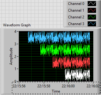
- Generated an array of 100-sample random to represent one second of a waveform.
- Created 4 waveforms on this 100-sample basis. The first waveform (channel 0) is just these 100 points. The second, 1 channel, is the concatenation of string 0 with the base of 100 samples, or a waveform "double". Channel 2 is 1 string concatenated with the base, and channel 3 is 2 string concatenated with the base.
- In order to trace the four channels that they rest 'on' the other, the waveform has the number of the channel added to it. Channel 3 is 3 + (4 copies of the basis of 100 points), a waveform 400-point random centered around a shift of 3.
- All channels have dt value 0.01 (but I guess I could have varied, as well).
- To make the channels start at different times, I started channel N N seconds before channel 0 (by subtracting the index of the loop, I, T0).
- For each channel, I created an attribute called "Chan" equal to "Channel N" (where N = 0, 1, 2 or 3, as the case may be).
This is the plot that results. Scale X is the absolute time value (no Date) using the 24-hour HH: mm
 S format. You can see that the plots are 1, 2, 3 and 4 seconds of time, and are offset from each other by a second. I used the trace attributes to change the name to the respective attribute.
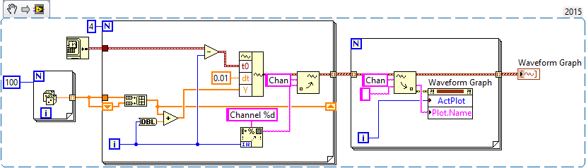
The code to do this is very simple - I almost don't need to show it, because I think it is completely described by the text above, but this is here:
Now, it was not that much faster that some of your previous posts, when you refused to your postcode, "guess us" what you wanted (but not to not correctly guess), you tried to "push" us in the right direction (still refuses to post code), and no one seemed very happy?
Bob Schor
-
PXI 2720: Conection for Multi channels
Hello
I put implement the multiple channels with resistance adjustment at the same time.
It is good to use '2720 Soft Panel', but I couldn't find the way to set up on my own Labview program using 272 X reference live
For example, I want to implement chan0 (80 ohm), (120ohm) chan1, chan3 (100ohm) etc.
I tried on one channel at a time. This is to give the new unstable resistance...
Is it possible to using X 272 screw reference?
Should I use "palett Ni272x-> advanced-> ni272x relay control multipe" fuction for their implementation?
Thank you
Insuk
Hello Insuk,
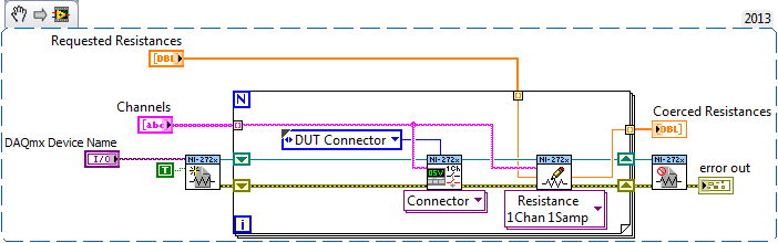
The NOR-272 x Resistance.vi for example is a good example of how define a single channel - to set multiple channels, call the 1Chan resistance ni272x 1Samp.vi to write for each channel you want to adjust.
Make sure you that you connect also each channel to the connector had TO plug into the front panel when you need to use it.
Here is an excerpt that should define a multiple channel resistance and connect these strings to the façade had TO connector:
Note: you can set the resistance without connecting to the connector HAD / DMM and then only connect to the connector HAD / DMM when necessary. I noticed that the '272 x Soft Front Panel' does not display the resistance of the channel if its not connected to a connector - the code snippet above to display the correct resistance in 272 x Soft Front Panel, but will also each channel link to the front panel. Make sure what you want to do this before starting the extract.
Make sure that you aren't opening and closing of the session each time you call the resistance VI write, this could cause you reset the unit each time, which would be left to zero all the other channels.
momo2013 wrote:
I tried on one channel at a time. This is to give the new unstable resistance...
I don't understand what you mean by «Who does give the new unstable resistance...» "If the code snippet above does not work, can you clarify on what is happening.
-Marshall G
National Instruments
-
10 data kech. / S for 28 channels
Hi all
On the ground, I have 28 channels of sensor data, the data rate is 10KS/S for each channel.
I store the data field up to 3 months to create historical reports or analysis of the conditions on the ground.
The data is very large, so I want to hear from you all to store as much data techinique or preferred way to store as much data.
: mansurprised:
Thanks for your suggestions.
The requirements of the project are already set by the customer. The client wants to complete 10K to 28 channels. He cannot afford the minimum sample rate or data loss.
I tried with the TDMS files to store 10 kech. / S (size SGL) given to 28 channels (sine wave); the size of the file is approximately 3.5 GB for 1 hour. The full-day data come around 84 GB, I'm not sure of the size of the TDMS file that can support up to as much of the file size, if it does not then support once again, I have to save the data to the full day in the whole of the bunch of TDMS files. Now if the customer wants to see the full data report 1 time in graphical format or in a table the task to perform the action takes around 2 to 3 minutes or some time it came up with an error like "not enough memory". If at the end of the day if the user wants to see the report full day how I can provide the report who have such huge data.
I use the LocalSystem PXI RT with a hard drive. PXI have always given 7 days as a backup, or in case of failure of the connection with the server, the backup data is in PXI.
So my question now even than the database or a file format I have to chosse store comprehensive data.
If there is no techinque to compress data, please suggest me.
-
What is the best way to change this program and to read 1 sample of each channel?
The initial program was conducted with NOR-traditional DAQ. I change it to DAQmx the best I could. The program, he is already the application of voltage to generate code (Daqmx Write.vi). But I have problems with the acquisition of tensions, give me readings rare (Daqmx Read.vi) I don't know if I have to make a (Daqmx start Task.vi) for each channel in the program or if I can make it work with a single. Notice I have no significant changes a lot because this program is already running in another lab, and they send us the program so we had no problems so much but rather than get the BNC-2090, they got the BNC-2090 is who uses DAQmx instead of the traditional. If anyone can help?
A BNC-2090 is just a connection block. It has no effect on the question of whether you should use traditional DAQ or DAQmx. Which is determined by the DAQ card that you are connected to the terminal block too.
You can refer to this document, differences between the BNC-2090 and connector BNC-2090 blocks has, but it's just saying to change the label of the Terminal Board to reflect the new DAQ cards.
What problems are you having with the new VI you just posted? You get an erro rmessage? I don't know what mean "rare readings.
You really shoud look at some cases DAQmx in the finder of the example. Some problems that you are experiencing, is that your blocks of data acquisition are all kinds of disconnected. Generally, you should connect the purple wire from your work function of creation, through the beginning, reading or writing, then the narrow task. Many of your data acquisition functions are sitting there on the small islands now. You should also connect to your son for the error.
With DAQmx, you should be combining all your analogue channels in a single task. It should resemble Dev0/AI0... AI7. Then use a sample of channel 1 N DAQmx read to get an array of the readings, you can then use array of index to break.
Other things you need to do is to replace the structures sequence stacked with flat sequence structures. Turn on automatic growth for some of your structures such as loops. At the end of the day, you might find, you can eliminate some of the structures of the sequence.
-
External hardrive dedicated for backups or huge 3 teg hardrive
I have two Macs. The two are not up-to-date on the operating system. One is a former PPC-Intel Power Mac G5 (running 10.4.8). This PPC has logic music software from apple and other software, that I like to keep the versions they all. I want to back up the entire hard drive please. Never done and need to know how?
The iMac I see a time machine... .the iMac running 10.6.8 and it seems pretty simple how to backup.
My question contains the questions above for backup but also do I need a hard disk dedicated for each backup of the computer, or can I partition a huge hard drive.
Also, so just save a computer for example do I need a dedicated external hardrive or can I use a space between an external hardrive with enough space for a backup.
I know that this issue contains various aspects of a question and different computers and versions so I appreciate the answers really. Thank you very much!
Every Mac should have at least 1 backup HD dedicated. When it comes to backup, it is wise to also have redundant backups because too backups fail! I have 3 Mac (iMac, Mac Mini & MacBook Air), each has 2 HD attached for redundant backups. Although I know that it is more expensive that you wanted to hear, it gives a pretty good backup level. It would be extremely rare to lose the primary storage and two backups, but I lost the primary and a backup at least 2 times!
In my case, I use Time Machine and SuperDuper as my backup solutions and also to use OWC (www.macsales.com) as my EHD.
-
Need for each week of grouping on a date column
Hi, I have the following query
Select user_name 'user who accessed '.
, count (user_name), "number of accessible times.
of apex_workspace_access_log
where application_id = 123
and TRUNC (access_date) BETWEEN to_date (1 July 2013 00:00:01 "," dd-mon-yyyy hh24:mi:ss') and to_date (4 August 2013 23:59:59 ',' dd-mon-yyyy hh24:mi:ss') Group of user_name,.
At the moment it displays the data for each day from July 1, 2013. I need to view the data in my application a week... We hear that he should consolidate the meter and the username per week.
as from July 1 to July 7, July 8-14 July, 15 July-21 July, 22 July to 28 July, 29 July - 4 August and so on.
Could you please let me know if we can do this via the query?
which can be achieved by putting Manik query as a point of view online by using the function command Rank by the number of the week.
Select user_name (user_name) count, rank() (command per week CSA) week from (SELECT user_name 'User who has consulted',
COUNT (user_name) 'number of times accessed.
TO_CHAR (access_Date, 'IW') week
Of apex_workspace_access_log
WHERE application_id = 123
AND TRUNC (access_date) BETWEEN TO_DATE (1 July 2013 00:00:01 ',)
"hh24:mi:ss mon-dd-yyyy")
AND TO_DATE (4 AUGUST 2013 23:59:59 ',)
"hh24:mi:ss mon-dd-yyyy")
GROUP BY user_name,to_char(access_date,'IW')
);
PS: He completely untested, but I guess it would help you to get the numbers of the week as well.
Maybe you are looking for
-
What is the best use of the flash storage based on PCIe?
On the Mac Pro, PCIe-based flash storage should be for applications? or? Thank you Diane
-
cannot connect my laptop HP with a predefined password
I put a password to connect to my HP laptop. Somehow it has stopped working. I was pretty sure that I entered the password. But he has shown the following message: "the user profile Service has no logon. User profile cannot be loaded. I really can't
-
To recharge without OS cd on laptop TOSHIBA preloaded Windows Vista Home Premium.
I have TOSHIBA laptop preloaded with Windows Vista Home Premium. Maybe I need to reload the operating system. Supply did not have CD of Vista. Key is given on laptop. How do I access the OS to recharge? A recovery disk is provided. Does include the O
-
Mistakes of creation of certificate file (.p12) Developer
Hello I'm so close to get an app on my playbook. I followed all the guides, and I'm stuck. Help, please! So I used the graphic Help and he got far enough along, but generates an error when you try to create the certificate in the wizard: Impossible t
-
When I install XP, I got 2 TB, but no access to the third to. That's why I need to reinstall. Help will be very appreciated.