delay between the trigger and data acquisition
Hi, I use NI SMU-6368 as a tool for data acquisition. In my experience, I use an external digital trigger to start taking measures of a thermistor.
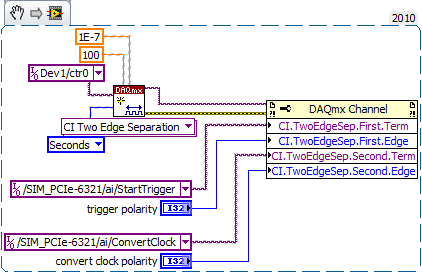
However, before the experience, I want to know the time that elapses between the detection of the trigger signal and data acquisition start time.
Is there a way to do this?
Here's the kind of thing I configure to get an accurate measure of time of t = 0 trigger signal to the
the actual first A/D conversion. It may be too much for a measurement of the temperature, but you should get
the right track.
-Kevin P
Tags: NI Software
Similar Questions
-
Hi all
Given the following data:
If I run the following query,A | START_DATE | END_DATE -------------------------------------------------------------- 1 | 01/01/1970 00:00:00 | NULL 2 | 01/01/1970 00:00:00 | NULL 3 | 01/01/2004 00:00:00 | NULL 4 | 01/01/2004 00:00:00 | 01/01/2007 00:00:00
I have only the first three rows. Why the fourth line is excluded?SELECT * FROM ( SELECT NVL(trim(TO_CHAR(A)),'-') AS "Code", NVL(trim(TO_CHAR(start_date)),'-') AS "Start", NVL(trim(TO_CHAR(end_date)),'-') AS "End" FROM my_table ORDER BY A ) WHERE ( '01/01/2004' BETWEEN to_date("Start",'DD/MM/YYYY') AND to_date( case "End" WHEN '-' then '31/12/9999' else '01/01/2007' END,'DD/MM/YYYY') )
Stephan
----------------------------
10.2.0.1.0 Oracle
Linux 32 bitYes, you're right it does not and, after working on it for more than an hour, I'm pretty sure it's a bug in the CASE statement.
Look at this:
Alter session set nls_date_format='YYYYMMDDHH24MISS';

SQL> SELECT
  2  Endd,
  3  case WHEN endd='*' then '-' else endd END,
  4  to_date(case WHEN endd='*' then '-' else endd END,'DD/MM/YYYY'),
  5  to_char(to_date(case WHEN endd='*' then '-' else endd END
  6  ,'DD/MM/YYYY'),'yyyymmddhh24miss')
  7  FROM (SELECT '01/01/2007' endd FROM DUAL);

ENDD       CASEWHENEN TO_DATE(CASEWH TO_CHAR(TO_DAT
---------- ---------- -------------- --------------
01/01/2007 01/01/2007 20070101000000 00000000000000
As you can see the Endd column is set to 01/01/2007 and this is the value of the CASE and the TO_DATE too. But when you convert it to a string using TO_CHAR you get 00000000000000.
This only happens if you use the CASE and compared, in the CASE WHEN clause, ENDD to something.
For example, this works:SQL> SELECT 2 Endd, 3 case WHEN 1=2 then '-' else endd END, 4 to_date(case WHEN 1=2 then '-' else endd END,'DD/MM/YYYY'), 5 to_char(to_date(case WHEN 1=2 then '-' else endd END,'DD/MM/YYYY'),'yyyymmddhh24miss') 6 FROM (SELECT '01/01/2007' endd FROM DUAL); ENDD CASEWHEN1= TO_DATE(CASEWH TO_CHAR(TO_DAT ---------- ---------- -------------- -------------- 01/01/2007 01/01/2007 20070101000000 20070101000000It is identical to the previous one except the CASE WHEN clause.
I did more than 20 different tests and whenever I put Endd in the CASE WHEN clause, the CASE seems to work fine, fact the TO_DATE but not the outermost TO_CHAR referring 00000000000000...As a workaraudo, you can use DECODE place od the CASE:
SQL> SELECT
  2    *
  3  FROM
  4    (
  5      SELECT
  6        NVL(trim(TO_CHAR(A)),'-') AS "Code",
  7        NVL(trim(TO_CHAR(start_date)),'-') AS "Start",
  8        NVL(trim(TO_CHAR(end_date)),'-') AS "End"
  9      FROM
 10        my_table
 11      ORDER BY
 12         A
 13    )
 14  WHERE
 15    (
 16      '01/01/2004' BETWEEN to_date("Start",'DD/MM/YYYY') AND
 17                           to_date(DECODE("End",'-','31/12/9999',"End"),'DD/MM/YYYY')
 18    )
 19  /

Code                                     Start      End
---------------------------------------- ---------- ----------
4                                        01/01/2004 01/01/2007
but I suggest you change the entire query to simplify it, like:
select a code, start_date "Start", end_date "End"
from my_table
where to_date('01/01/2004','dd/mm/yyyy') BETWEEN start_date
      and nvl(end_date,to_date('31/12/4712','DD/MM/YYYY'));
Published by: Massimo Ruocchio, December 19, 2009 15:52
All of the above queries were run on 10.2.0.1 the same version used by the Po.
I tested all applications above on 9.2.0.4, 10.2.0.4 11.1.0.6 and everything works fine.
Now, I'm sure it's a bug of the 10.2.0.1 version.Max
[My Italian Blog Oracle | http://oracleitalia.wordpress.com/2009/12/19/totali-parziali-con-group-by-rollup/] -
motion control for vertical actuator and data acquisition
Hello
I am a researcher (a branch of civil engineering) geotechnical engineering and I have very little knowledge about the acquisition of control and data motion, so would need a lot of help from the experts OR. I have only knowledge base on these 2 aspects based on my reading of some materials on the Web site of NOR and youtube videos, so I hope that you bare with me
 . Here are my questions:
I am trying to build an actuator which will be used to push a probe (a penetrometer with a load cell to measure the resistance of a soil sample), resembling the concept, photography in the attached file. I need to have these criteria for my system:
(1) actuator, which can push the probe at speeds between 0.01 mm/s - 300 mm/s with precision and move the probe cyclically (upwards and downwards) in the vertical direction
(2) load expected on the probe into the ground range: 0.02kN - 6 kN.
(3) necessary to get the load cell load data and the speed of the probe.4) able to control the actuator to a PC (speed and posotion) and monitor data from transducers and data log time even the transducers.
Guess my beginners is that I will need:
For orders:
(1) software - LabVIEW and NOR-motion assistant(2) controller - NI PCI-7342
(3) driver/amplifier - analogue servo AKD Drive
(4) motor - motor brushless servo AKM
For the acquisition:
(1) software - based LabVIEW development systems(2) amplifiers or other device - no idea what type on the conditioning of signals
(3) data acquisition device - no idea what type
Since I'm a beginner, is - that someone might recommend components (hardware and software) for the control and data acquisition. I'm on a tight budget, so I thankful if someone could help me to recommend components good enough to build my system.
Thanks for your help.
At these rates, you will need to run the sensor for the cDAQ. You can configure the analog output on the Tritex nationally on the position. There is an adjustable filter that you can set in order to get a clean enough to 300 Hz signal. When you learn about the Tritex, make sure that let you them know what comms and e/s that you want to use. If I remember, not all options have worked together. The analog output may need to be my, but you can put a resistance through the acquisition of input data to get the voltage instead. I don't remember all the details. You should really not too much on the Tritex/LabVIEW side. You will send your movement parameters (beginning of end of race, speed, position, accel, cut), and if you cycle (I believe you) or simply running in a loop. You could also just be able to use the functions of jog. When you get close to knowing exaclty what you need, PM me and I'm sure we can work something out with the drivers. You need only the basics. In fact, you could probably do this all your movements via digital and analog i/o.
-
I am acquiring several channels of analog voltage input at the same time, I need to send an output analog two seconds after the start of the entry.
I'm running an experience with accelerometers on a query table.
I start the trigger and the table remains still for two seconds, which allows a reference level for all sensors.
Then the output signal of the VI removes the break in the motor controller.
The speed measured by the encoder is sent to one of the input channels.In this way, our accel and speed data are synchronized.
After it acquired the analog input data out put must be reset to zero.
MULTI.vi I've updated the link above works of VI, I used a property node to solve the problem.
-
Why my display of the date of the mailbox does not have a / between the year and the month?
I'm talking here about how the date of different e-mails appear in my Inbox. I have a / between the month and the day, and a / after the day, but I did not / between the year and the month.
TB uses the date format short, such that defined by your operating system, which, in the case of Windows, is located in the Panel control/region and language.
http://KB.mozillazine.org/Date_display_format
There are a few modules that might also be useful:
https://addons.Mozilla.org/en-us/Thunderbird/addon/ConfigDate/
https://addons.Mozilla.org/en-us/Thunderbird/addon/Super-date-format/
http://chrisramsden.vfast.co.UK/3_How_to_install_Add-ons_in_Thunderbird.html
-
Delay between the addition of peripheral support and to be visible?
I added a device supported in the portal provider. When I disconnect and reconnect and check, it is there in the list of devices selected for this version. However, it does not appear in the list of devices if I check in the App World. Is there a delay between the addition of new devices and them being visible/allowed to download? How long is it? Or is there something else I need to do to add new devices supported for existing versions?
I believe that the original deadline for metadata changes is nominally a day, while there may be further delays (up to a week?) so the App World client is caching information. I don't think that there is a good description of what exactly is subject either of these delays, but it's a good bet that you will see at least one. These are probably not involved if you view App World via a web browser.
-
Trouble with the voice and data Vlan vlan translate between CT3905 and SF300 - 24 p
Hey actually, we have the solution to monitoring of implementation with CT3905 phone, SF300 - switches 24 p cameras and AIR-AP1041N Access Points

We have the problem with the vlan tag in SF300 switch ports - 24 p we can´t tag vlan of the voice and data VLANs on the same port on SF300 - 24 p it is Possible or we must dedicate a port for each VLAN or ussing the same data segment of VLANs and vlan voice?
Someone has an answer or technical documentation that can help us
Best regards
First of all,
Please disable lldp transmit in SF 300 switch.
The command is "no lldp transmitted."
After you disable check the following steps.
https://supportforums.Cisco.com/docs/doc-27005
facing the same problem with cisco SG 300 and 3905 ip phone switch.
And nested thing was my 7945 and 6941 phones use to work properly, without above configuration.
Cisco 3905 became not vlan Ip address votes and even if I put static, it did not work.
After a long struggle, I was able to solve the problem. Now both phone and system work fine in the same port.
Samantha
-
Card FPGA and data acquisition synchronization
Hi, we are control and data acquisition of several hardware devices (including Photodetectors and translational stages). Until last week, we used all the controls and acquisition using a PCIe-7852R FPGA board. However, we decided to move the acquisition part to a PCIe 6363 DAQ card to improve the sharpness of the tension. During the test, I found that the internal clocks in the FPGA and the DAQ cards are slightly inconsistent (not just a phase delay, but a difference in the period).
I know because I have generated a square wave (period = 20) using the FPGA and gains using the data acquisition card (at a rate of 200 kHz, that is, 1 taste every 5). I have observed acquired place shifts 5 every 5 seconds approximately. Such a change does not occur if the production and acquisition is done using the same Board. Therefore, the only explanation is that the data acquisition and FPGA cards clock frequencies are different. According to my calculations, the percentage difference between their time clock must be 5/5 s = 0.0001%.
Therefore, I wonder if there is anyway to synchronize clocks between them. Or, is it possible that I can drive the FPGA clock-based DAQ hardware, or vice versa? Also, please let me know if there is something trivial as I fix.
Thank you very much.
Kind regards
Varun
Hi Varun,
my post was only one solution...
Your data acquisition card may take an entry to control sampling of trigger. In this mode, samples draw on a rising edge of the external clock signal. As long as you stay within the limits of the DAQ (100 MHz for your card) material sampling works perfectly. There are even examples coming with LabVIEW explaining how to program your data acquisition card...
This mode use you your FPGA as clock source sampling for data acquisition. Both will run on the FPGA clock in sync. When the FPGA is a bit out of 40 MHz, so it won't matter because both devices are triggered on the same clock signal...
-
Control and simulation and data acquisition
Hello
I am applying to motor control in Labview. I'm sampling speed from DC engine in real time through an acquisition of data. (my sampling time is 1000 samples per second)
Then wrap speed as input to a Simulation (simulation and design of the order) and inside the loop simulation, I have a PID controller. The PID has the actual speed of the engine for the acquisition of data and the engine reference speed as input.
Reference engine speed comes from the generator of signals (control design and simulation-Simulation) and is a waveform.
My step in the engine size is 1000.
I am running this application real-time and drawing the reference signal and the motor real signals. I run into several problems with regard to the calendar.
1. when I change the size of the step of the simulation loop, the frequency of squares of reference also seems to change. For example. What step size = 1000, duration of pulse = 1 s. What step size = 100, pulse width = 0.1. (My pulse frequency is 1 Hz, Simulation clock - 10 kHz). How step size can affect the pulse width.
2. can you explain the relationship between the DAQ, the Simulation step size loop sampling time, Loop Simulation period.
3. If I want to collect different sets of data using sampling different hours, it's OK to change the sampling DAQ time without changing the size of the step of the simulation.
Would also like to emphasize that the DAQmx calendar under sample clock mode is placed in front of the simulation loop and the output is connected to the loop simulation.
Appreciate any help.
Hello
Maybe some screenshots of your code would help. Furthermore, what you have read your samples together with your DAQ screws?
(1) If you have a waveform, the output is specified as:
For example, if you change the size of the step of the simulation loop, you change the simulation time which are introduced into the signal generator and affecting the waveform that you see if you do not have a size quite small step to characterize the waveform that you generate.
(2) sampling DAQ rate is the speed at which samples are taken on the acquisition of card data itself. The size of the simulation step, help. "Specifies the interval between the time when the ODE Solver evaluates the model and updates the results of the model, in a few seconds." Simulation loop, still using, "Indicates the amount of time that elapses between two subsequent iterations of the loop of control & Simulation.". " "Step size determine the value of t that is introduced to the functions you use in the loop simulation while the loop simulation period controls simply to how fast you change the following t value. The sampling rate of DAQ hardware is a clock of completely separate hardware controlling the analogue-digital on the DAQ card converter so that you can get a deterministic dt between the samples being acquired.
(3) you can change the schedule for the acquisition of data, but you will need to restart each time the changes take effect. If you change the calendar of data acquisition and want your values to correlate with your simulation, you will need to change your size of step as well.
-Zach
-Zach
-
What is the difference between the IO and line?
Hi all
I'm using Labview 7 and in my mahcine I have an installed 6013 card. However, there was an interface card designed by someone else long ago, on the table, only AO0, AO1,..., A07, DIO0, DIO1,..., DIO7 were printed. In the program, I saw some code to write to digital Line.vi allows you to send data to the digial io. Say that I write for DIO 3, so I understand here DIO 3 means the channel of e/s 3, but online? What is the difference between the channel and the line? When I write the data to a single channel of e/s, are us wriitng a byte or a bit of it? Thank you.
A channel is usually used with inputs/outputs analog. Each AI or AO is a string.
-
The reading of data acquisition via tcp
Hello
I am building an application that controls an acquisition of data via tcp.
I have a JAVA program that communicate with labview, give a command and data acquisition starts. (So, I read the correct Java data at Labview)
My problem is if I try to read data acquired by data acquisition (continuous sample 1 k samples), I've read strange values.
I transform of double values in the string and send it via tcp.
How can I read it in Java? What type of socket should I use? What is a rate problem?
I also tried to transform small/big-endian byte order, but it does not work.I enclose a sketch of this part of the application.
Please help me, I try for 2 weeks!
Thank you all...I find the solution in the lavag forum.
I post here, if it can help someone.http://lavag.org/topic/16359-sending-LabVIEW-data-via-TCP/page__pid__99983#entry99983
-
What is the difference between the KING and ACQWINDOW regarding the attributes of the camera?
There are two sets of attributes for, left, top, width, and height.
For example, there
IMG_ATTR_ROI_WIDTH vs IMG_ATTR_ACQWINDOW_WIDTH
MG_ATTR_ROI_HEIGHT vs IMG_ATTR_ACQWINDOW_HEIGHT
What are the differences between the KING and ACQWINDOW?
Thank you.
Hi sunspotzsz!
Vision consists of two main steps: acquisition and image processing. IMG_ATTR_ACQWINDOW_WIDTH would the acquisition, and IMG_ATTR_ROI_WIDTH should be part of the treatment. Therefore, if you set the ACQWINDOW_WIDTH to 100 so that numbers all pixels that are acquired will be set to 100, and they will be stored in a buffer. ROI_WIDTH will use an image that is already in memory and 'zoom' so that the only part of the image you are watching / treatment.
Also, take a look at this knowledge base on the Kings: KING FAQ you may find it useful!
Kristen H.
-
What is the difference between the stop and restart?
What is the difference between the stop and restart? I feel that stopping closed all processes, completely erases RAM memory and clears the cache of the processor. I need to know if 1) this is a correct assumption and 2) which is better for daily maintenance of the system. Thank you in advance.
Hello Jeremy_1976,
Your support when the judgment is correct. Basically, it stops the process and completely turns off your computer. Reboot, however, temporarily your PC stops, then turn it on again. This happens usually when Windows updates are installed. After installation, the system is restarted (rebooted) so that any update has been successfully installed and works as it should. You can be a little mixed upward the reboot and the hibernation. Reboot is, as I have indicated previously, basically a reboot of your machine. Ultimately, your PC is on again after a reboot. However, hibernation, stores all data currently in memory in a special file, then the PC turns off. When you then turn on your PC, that is, coming out of hibernation, hibernation files is used to restore the status of the PC than when you initially put into hibernation. In other words all the programs you had open before will automatically open and be ready to use hibernation.
Hibernation or sleep for that matter is for short-term use. It is normal in Hibernate, or sleep if you want to be away from your PC for half an hour or so. If you leave more than I suggest you stop completely.
A point to remember about hibernation is that, if you use put into hibernation, you can't, once you get out after hibernation, install programs or updates. You have to stop and restart normally to do.
This forum post is my own opinion and does not necessarily reflect the opinion or the opinion of Microsoft, its employees or other MVPS.
John Barnett MVP: Windows XP Expert associated with: Windows Expert - consumer: www.winuser.co.uk | vistasupport.mvps.org | xphelpandsupport.mvps.org | www.silversurfer-Guide.com
-
"There is a time difference between the client and the server"
Unit 4.0.3
Everything worked very well, and all of a sudden, I'm not able to connect to the server unit using any domain account. When I enter the domain/name username/password, I get this error message:
************************************************
The system is unable to log on due to the following error:
There is a time difference between the client and the server.
Try again or contact your system administrator.
**************************************************
I can use the same domain account (unityinstall) and the journal in other machines. I can connect the machine to the unit using a local account. There is no time difference between the DC server and unity.
Need help,
Thank you
Partha
Log on to your LOCAL computer using an account that has privileges
At the command prompt, type the following:
NET TIME ancien_mot_passe/set
Found this on the MS site:
Cannot open a session if the Date and time are not synchronized
http://support.Microsoft.com/default.aspx?scid=kb;en-us;232386&product=Win2000
-
Encrypted L3 Communications between the TOWER and WLC?
Hi all
I work with a client who wants to put the towers away to their WLC (a 4402). The problem is that communications between the TOWER and WLC must be secured, even through their private Wan! I have a few questions that result, if someone is able to help you;
- I can't know if and what method of encryption is (is it AES etc.?) used on connections between towers and the WLC and what are the steps?
- The terminology can be a problem here, it's not a wireless mesh, just classic LAP for WLC
- EXTENSIVE customer network is already encrypted (IPSec VPN via VPLS) in parts - what is the consequence of execution of AP<-->WLC with end to end (if possible) on a network encryption EXTENDED with IPSec, i.e. double encryption?
Strange but true - pointers will be greatly appreciated... Phil.C
With a controller of the 4400 series, the control traffic between the AP and the regulator is already encrypted AES. The user traffic is not encrypted. If you use a 5508 controller all traffic between the AP and the controller is encrypted AES.
For what is running the traffic through a VPN, it should work. The issue I see with this is with the MTU in general. The controller will drop all packets with a payload of less than 32bytes data. According to the MTU over the VPN I've seen packets getting fragmented and it is a question. If you use one of the versions CAPWAP (5.2 or newer) discovery dynamic MTU is part of the Protocol and this MTU problem does not really exist.
- I can't know if and what method of encryption is (is it AES etc.?) used on connections between towers and the WLC and what are the steps?

Maybe you are looking for
-
How to set up the printer for the greeting card envelopes 5-3/4 x 9
-
Priority interrupt function is driving me crazy! I don't know why, but it starts to turn himself and so I keep missing calls, email, etc, etc. Can someone tell me PLEASE how to permanently disable this annoying "feature"?
-
Pen digitizer yoga ThinkPad not replaceable?
Hi all I bought a thinkpad yoga with digitizer and when I tried to change the digitizer pen I can't get out. (I'm thinking a tib felt or rubber could never scratch the screen and he could give a better idea)I tried the wacom tool to get the pen out a
-
Hello I use a cRIO 9031 to collect the UDP data and save it in a file. Is it possible to save the raw data from UDP nothing else than a string? For example, the first line of the UDP data is 0400 0000 8E0D 4904 SCN1
-
Bug when I press the < TAB > key
How to reproduce this bug: In new VI, create a Boolean value and control on a tab on the front panel control. On the block diagram-> insert this control in while loop. Right click-> properties-> navigation key boolean Control-> click on "ignore this