derivative
How can I find and highlight a symbol in a document of dc from adobe. I'm a cross stitcher. My bosses are in PDF format and each page is a complete graph of different symbols. I want to be able to highlight a symbol in a document and then turn off highlight it or highlight the next symbol in a different color. Can someone help me with how to do it if it's possible, please?
MsKayle
Hello.
Check out these free shares for Acrobat:
- https://acrobatusers.com/actions-exchange/find-highlight-and-extract
- https://acrobatusers.com/actions-exchange/find-and-highlight-words
Tags: Acrobat
Similar Questions
-
Clocks on board and derivatives of FPGA
Hello
I use a PCIe FPGA 7852R card to collect data at 200 kHz of channel 5. I was pretty confident that my collection frequency was correct, because my program was based on a derived clock of 40 MHz I had chosen to use a derived clock because the on-board clock is running at 40,02 MHz (instead of the 40 MHz specified for some unknown reason I ignored).
However, today one of the members of the LabVIEW support team told me that the FPGA clock rate may change during the compilation and optimization (constraints). He stressed that if the FPGA can run that fast, then it displays an error (as you might expect). He said also that in some cases, the on-board clock can run faster, but in this case no error will be displayed. I saw no errors in the past (which means that the system had no problem with that fast running), however, I'm not sure if during one of my compilations my derived clock could have run faster than 40 MHz. If it can happen? This will affect the time of all of my previously acquired data. Unfortunately, I have not saved any of my journal compilation of
 .
.Thank you very much in advance.
Kind regards
Varun
Hi VarunSreenivasan,
I think that our support has meant that compile logs will show you some pieces of logic could operate at higher speeds. During the process of compilation, the compiler will determine the clock frequency more rapid that can be used for your logic and to ensure that the configured clock frequency is less than or equal to this value. If you have decided to try to run your code to 200 MHz and logic cannot run this fast, then you get an error. If you have decided to run your logic to 200 kHz and it is possible to run faster compilation logs will show you then the max frequency that will work, but the logic still run to 200 kHz. The code should run no faster than the frequency you specified.
-
Why do I get 2 different results of these identical derivatives screws?
I wrote two calculator derived from point by point identical screws and I am at a loss about why
I get two different results. I don't know what I have missed/missing which is the origin of this anomaly.
Please take a look at the downloaded screw (written in LabVIEW 8.0) and let me know what I did wrong.
Perhaps they are not the same after all.
Tips for troubleshooting or suggestions are welcome!
Thank you
noviceLabVIEWuser
item 1 of table 1 = 0.9998899980
item 1 of table 2 = 0.9998900000
Change the format to display the different values

the code is identical
-
Delay FPGA using a derived clock
Hello
Probably a simple answer to this. I have the PXI-7813R that has a clock of 40 MHz I database I need to create a delay time of 488nSecs in my code. Unfortunately with 40 MHz, I choose 475nSecs or 500nSecs. If I use a clock derived from 80 MHz I get a 487.5 delay which is very close to what I need. However, if I change my level above 80 MHz clock I get various offences of timing during compilation. Is there a way to keep the clock of 40 MHz top-level, but use the clock of 80 MHz for a time delay?
Thank you
Andy
Hi Andrew_Quick
Do you use this clock derived on a SCTL? I did some research on your question and find Knowledge Base article next talks a little about the way in which the clocks derivatives works with the SCTLs and in section shifts, there is a note that some codes can compile not at higher rates at 40 Mhz due to the time constraints of the FPGA , so I think that you should check that you don't have warnings or suggestions for when creating your clock derived to your target.
Even if you select the clock 40 MHz as the top level, if you select the clock of 80 MHz for the timed loop, the compiler will have to adapt all functions in the FPGA, and according to the error that you get that may be causing the violation of timing.
Hope you find it useful!
-
Hi all,
All those put in place an object derived from NationalInstruments.UI.YAxis to display the MajorDivision and MinorDivisions form 360 angles?
In this way, instead of display
3
2
1
0
-1
-2
-3
Display the tick-mark labels
3
2
1
0
359
358
357
I guess it would be like adding a new type of string in the shape which would be 'modulo 360'.
If someone has an idea, I'd appreciate Info!
See you soon,.
CD
I found answer myself!
I created this class:
Class clNI_CustomFormatString360
Inherits FormatString
Private decimals_ As Integer = 0
Public Sub New (ByVal decimals As Integer)
MyBase.New (FormatStringMode.Numeric, "G5")
decimals_ = decimal
End SubPublic Overrides Function FormatDouble(ByVal value As Double) As String
<>
value = 360
End while
While the value > = 360
value-= 360
End while
Return MyBase.FormatDouble (Math.Round (value, decimals_))
End Function
End ClassAnd then in my code I attribute:
myScatterGraph.YAxes (0). MajorDivisions.LabelFormat = New clNI_CustomFormatString360 (1)
Who did the trick!
-
Hello
I'm new to labview and this question might seem insignificant to you.
Here's what I'm trying to do:
I have two tables (generated via loops). I want to calculate the derivative of table 1, with regard to table 2 and then draw the resulting table of the table 2 vs.
My VI (joint) is not what I'm trying to do.
Help, please.
The dt is generally the difference between the x values (function assumes that the x values are equidistant, who they are). Thus, for dt, thake simply the difference between the two adjacent values x.
All you need is a simple loop? The formula node seems exaggerated, for example, the division by two should be performed once before the loop.
Here's how you can simplify... makes sense?

-
I am tring to derive a clock to 25 MHz using an NI PXI-7842R and labview project will not allow exact clock
But when I try to do the same thing for a PXI-7830R target, I'm successful.
What is going on?
I choose a base of 40 MHz clock
for 25 MHz, the multiplier is 5 and the divisor is 8
When I right click on the clock of new derivatives, I get only the possibility to enter a new frequency of the clock.
Why doesn't the tool let me simply specify the multiplier and divisor?
I'm using Labview version 2010
That should work just fine. The structure of the case will add some overhead to the total runtime of the circuit, but at 50 MHz, these costs should be minimal and you should not encounter many problems of timing.
-
How to take a derivative of a sine wave?
I know this is probably very simple and I'm sure that I'm doing something stupid, but please could someone help me... I'm just trying to draw the derivative of a sine wave on the same graph as the original sine wave. There seems to be working (it shows a cosine wave), but the magnitude is far away. Please could someone just point to me why the amplitude is off... the original sine wave going between 1 and -1, but the derivative is between 60 and -60
Just speculating, but...
- The derivative of a sinusoid of 10 Hz should have an amplitude of ±60 remarks (2 * pi * 10).
- The VI of sinusoidal waveform has a default frequency of 10 Hz.
Coincidence?
Best regards
-
Help derivatives (probably my ignorance)
I take the derivative of a curve of time of position to get the speed. This works except the first and the last point vertically shot excessively. This is probably where my ignorance of not being in a classroom of calculation in a while. I guess it has something to do with how the functions derived from VI.
I've attached an example graph to show what he does.
You have a very large DC offset in the data. Average about 5.7 with variations less than 0.1. Subtract the average before you take the derivative.
The top graph is derived from (signal - average). Chart at the bottom is the signal.
Lynn
-
Compute the derivative of custom
Hello world
I would like to calculate a custom derivative (derived from two points to be precise) of my data. The derivative of two points means that df (x) /dx = [f(x+h) f (x - h)] / 2 h, rather than df (x) /dx = [f (x) f (x - h)] / h. I am a beginner of Labview and have no idea of what is the best way to handle this, but I suspect that you are using a loop with a formula node where the data are fed through shift registers would be the way to go.
Currently I have my data generated in the form of two tables 1 d (voltage & current) which are converted to a 1 d of cluster of 2 elements table and plotted on a graph. It would be very useful to have another chart that shows the derivative of two points.
Thanks in advance for any help with his.
This is an implementation using the data points. He accepts not evenly spaced data.
Lynn
-
Hello, I'm getting data in Excel in table, then I use block 'sim arbitrary signal' to define a dt I need and to trace the signal (it is the voltage signal). Then I need to get a 1st derivative of this signal. and here I'm getting cause problems after the use of derivatives of (time domain GIS pallete) my drift does not seem appropriate. Is there someone who could help me? You can see the attachments to some piece of my chart of drift of Signal voltage and VI, graphic of the voltage Signal
-
Issue of signal processing: first slope of tangetial derived vs?
Hello world
I have a question about a strain signal processing...
Do the terms of the "first derivative" and "tangential slope" essentially refers to the exact same property; It is the change in the strain (y) compared to the change in time (x) in a precise point in time...
I determined the rate of development of strains of calulating the first derivatives all points of data within segement signal of interest and obtained the average value dx/dt for the analysis... Is this the same as "means tangential slope? Or they the different?... My base, understand that they are one and the same... Could someone please confirm or correct this?
Any feedback is greatly appreciated.
Kind regards
Jack
The tangential slope of a curved line represents the slope of the tangent line to the curve at a point. This can be calculated by taking the first derivative of the function and the evaluation to the point. Yes, to all intents and purposes, "first derivative" and "tangential slope" refers to the same property.
I guess that the average tangential slope could be calculated by taking the average of the evaluated derivatives. A quick Google search confirms this. I am a physicist, not a guy from the DSP, so maybe my opinion is not correct.
You can also watch how you calculate your drift. The default LabVIEW method is a simple calculation of two points which is very sensitive to noise. If you have a fairly new version of LabVIEW, there included functions that calculate the Savitzky-Golay coefficients which you then use with the convolution filter to determine derivatives at each point. Savitzky-Golay method essentially computes a method of least squares adjustment to a polynomial to each point and takes the derivative of the polynomial. This greatly reduces the noise. Note that the coefficients Savitzky-Golay may be used to generate any order, provided you use enough points for the convolution. The default value is an order of zero, or smoothing filter. If your version of LabVIEW is not new enough to contain the Savitzky-Golay coefficient generator, you can do it yourself fairly easily. A quick search on the internet for "Coefficients of Savitzky-Golay" should give you the formulas.
However, as you take the average of a lot of points if do you or not will depend on how much noise your data contains, how many points are your average, and how many resolution/precision you need.
Let us know if you have any other questions.
-
PtByPt; Question of derivatives
Hello
I'm working on a program that read data from serial port (FS = 1000) permanently. I chose to read the data in blocks of 512 loop producer and send it via FIFO to the consumption loop. On the consumption loop, I want to filter and get the signal drift. I wrote a simple program to illustrate my problem, the program simply produce a sine wave of 128 point per cycle and this wave to filter with a bandpass filter (assuming a 1280 Hz FS). Which works very well! What I don't understand, it is the derived part and meaning of dt. I wait, it should be 1/1280 but this givs an answear wronge. I saw a solution in which they take the difference between Xn - 1 and X 0 of the signal block and insert it into dt
 if I read the description in the derivtive sense of dt is sampling interval and it should not be less than or equal to zero. So what did I lack?
ahmalk71 wrote: I started with your suggestion, what I get is a derivative that is 63.8 times

If you go through the math, that's right.
d (sin (2 * pi * x 128) /dt = 2 * pi * 128 * cos(2*pi*128x) /dt.) With dt = 1/1280, that you end up with 20 * pi * cos(2*pi*128x). 20 * pi = ~63.8
-
labiew with map of derivation lpc2148
Can I use the labview for arm with a derivation LPC2148 module?, or I have to use expert advice to use with the Labview?
Do I need cable JTAG ARMS - program with Labview, or can I use the bootloader inside the arm processor and program seial port?
You can use http://www.ni.com/labview/arm/ (LabVIEW Embedded Module) for the ARMS controllers.
As for programming, you can call the LPC2000 Flash ISP utility, which automatically call ISP bootloader and program controller arm.
-
The transfer of the PID block function does not show the derivator.
Hello
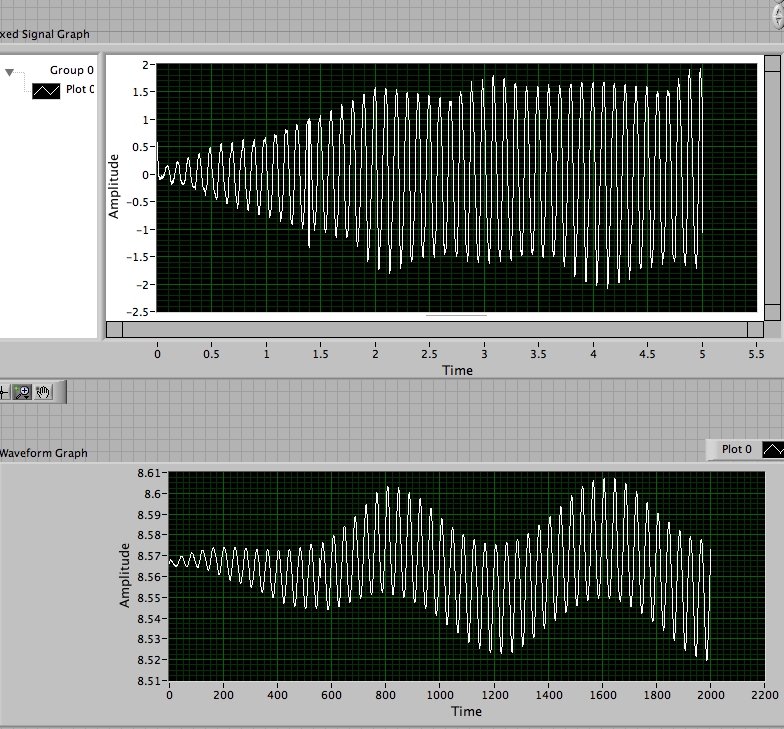
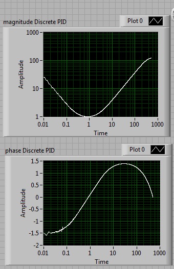
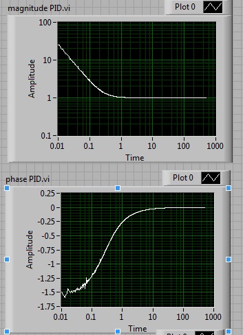
I try to use the vi of PID, but I when I try the box by itself, it does not behave as a 'classic' PID should behave. The main problem is that I can't see the derivator. In the attached vi, I compare the transfer function of the PID vi with the function of transfer of a PID built by me. My version shows should have all what a PID: section integral (with an amplitude decreasing and phase-90), Center (with a constant amplitude and phase 0) and area derived (with the magnitude and the phase of + 90).
The PID vi shows that the part.
You can also select a progressive input signal and see the result directly. If you choose a large enough time to bypass (100 times greater than the time to the Integrator), and you look closely at the first part of the output, you will see the choice because of the derivator in my version, but not in the version PID.vi.
Anyone know what I am doing wrong?
Kind regards
Pablo Estevez
Nathand dear,
Thanks for your reply, I tried the change and you are right. This shows that's not a PID standard, since this means (and in fact I can see it now by checking within the vi) is not using the derivative of the error, but the derivative of the process variable. I know that it is sometimes used to prevent the effect of fast changing set points, but it's a shame that they don't how about it in the help, and that's not a selectable feature. Do you know if there is a way to edit these pre-packaged vi?
Another question, about the style of labview. I've included the footage just for the terms of the Group and to make the code more readable separate the integrator of the derivator and not having a knot of tangled signals. Especially when I run the cleaning diagram, it becomes very tangled. I searched for another way to do this (container boxes, groups). Would be nice if you could suggest me something that I can do for her.
Thanks again,
Pablo
-
Accounting of the derivative of the signal
Hello
I am a beginner LabVIEW-user and I have a question that maybe painfully obvious for a more experienced user.
I use a precision Sartorius CP225D balance to save the change of mass scale mg due to withdrawal and the dispensation of a fluid in a container. What is the piece of blocking air flow, bringing the temperature of the room and immutable or reposition the initial load for several hours, a fairly linear and continuous negative drift will occur for the display of the balance. This drift occurs without worrying if there is anything on the scale or not. I use VI Sartorius provided to read and note the readings.
How can I use LabVIEW to adjust this signal for this negative drift using the linear relationship I can derive from the previous examples of execution? I tried to collect the signal of the difference between the display of the balance and the linear relationship that I approached, but with time, even this manipulated signal falls to the display of the exact balance if he were allowed to run without being manipulated. Better yet, how can I manipulate the signal of a frame sequence curve flat prior connection for the signal already recorded in the following picture?
I would appreciate any guidance or assistance that could lead me to a solution. I tried to contact helpline Sartorius, but little help was offered. I will share as much information as possible.
Thank you for reading this,
Zach
Zach,
The instrument drift probably not linearly forever or the value wouldn't finally out of reach. The manual I have donwloaded requires 30 miniute, 4 hours or 24 hours of warm-up, depending on the model and the application.
You can try saving records once per minute for 24 hours, starting by an intstrument of cold and let it run as stable an environment that you have available? Note the temperature, if possible. Never stabilizes the drift?
What is drifting from the signal you need to measure? What is drifting? How fast your fluid distribution affect the readings?
Lynn
Maybe you are looking for
-
Satellite L650 - left mouse button starts to unravel
I have some problems with my left mouse buttons on my Toshiba Satellite L650 - 1 6.Sometimes it doesn't work and I don't know what to do. What should I do?
-
Pavillion dv6: how to get rid of the sound on hp Pavilion dv6 bar 2010
I have hp pavillion dv6 with a bar of his touch above the keyboard of 2010. When I turn to the top or down the volume a soundbar appears on the middle of the screen. It's a little bit boring when I'm in a game, because it closes the game when I have
-
Equium M50: How do I change the details of Wlan WEP?
Does anyone know how to change the WEP (?) details on an Equium M50, I just signed up to broadband wireless Orange and they tell me that their WEP key is 26 digits and look only some old pc for 23 codes numbers? I can't put my wireless switch on and
-
When I turn on the computer everything works fine, but after that I was online the desktop icons do not work and if I right click on the desktop nothing happens. The icons in the taskbar are not affected and work well.
-
Unable to play old songs or backup and restore in Media Player
original title: license problem I could listen to my music with WMP 10 very well until I did the updates of windows last week. Now, any file over two years will not play. When I try to play a song it turns orange information. When I click with the ri