Descaling of FFT waveform
If this has been asked several times.
You don't have a spike at 10 and also to 990 that corresponds to 10 Hz. You can activate the displacement of the FFT to obtain the chart based on the DC.
Tags: NI Software
Similar Questions
-
Hi all
I am fairly new to LabView and data acquisition. Sorry to bother you. I have a question:
"I recorded a waveform distorted by using digital oscilloscope. The format of the file is .bmp i.e. photo brush. I want to perform the FFT of this waveform analysis. How can I do in Labview? I already have the magnitude spectrum using the FFT of the oscilloscope mode, but I need to get the spectrum in phase as well so that I get the angle of phase for each of the harmonics. Would you be very kind to guide me in this regard? »
Thanking in anticipation.
Best regards
Hernu
-
FFT waveform (file converted from Matt file lvm) - how to overcome the error dt < = 0?
Hello
I use a lvm file after conversion of Matt file. I wanted to get the fft spectrum. I get this error message this dt waveform<>
How he overcome?
I have attached the matte file and the vi that I used.
Best regards
FESMI
The Forum is a bit special files that can be attached. Creating a zip file often works. Sometimes, you can change the .txt extension. If you change the extension, please indicate in your message which was the extension of the moose.
It seems that data in the file has a time column and a column of amplitude. The LabVIEW waveform data type is a cluster of a table of amplitudes (Y), sampling interval (dt), from the time (t0) and optional attributes. That's what the power spectrum VI requires as input. The t0 values is not used if the default is fine. the value of dt can be calculated by the difference of the two adjacent values in the time column. Given that the first value is equal to zero, the second value is equal to dt. Use the primitive to build a waveform of the palette of waveform. Expand it to view the dt element.
In the VI attached all lines is an indicator that contains your saved default file data. Graph XY plots that data. After subtracting the way to get rid of a continuous component, the data is converted to a waveform. The power spectrum is calculated and displayed using the same VI as in your program. It also uses extract several Information.vi tone for the frequency and amplitude of the main peaks in the data.
Interestingly, the lower frequency of the spectrum a harmonic of 60 Hz while the tops are almost sharp space 4 kHz ~ 100 Hz apart. The broad peak near 2.1 kHz does not seem to have noticeable components to 60 or 100 Hz.
How to avoid the Type of dynamic data (DDT)? Stop using screw Express! For reasons known only to EITHER screw Express a deliver their outputs via the DDT. Except when you open the block diagram of the express VI, there is no way of knowing what the underlying data structure on a thread of DDT.
Lynn
-
Hi, I work analyze signals of vibration thanks to tiara, data are from 4 to 5 million points in three or four hours, the problem is when I run the analysis FFT only shows me frequencys up to 300 Hz when I know that I measured frequencys of 3 500 Hz.
The measurement parameters:
Frequency: Hz 12800
Number of samples: 1200
Tiara parameters:
Values: 4 757 810
Time: 11:24-14:12
To match my data with time in tiara, I divide the number of values between the seconds of the archipelago.
It was my setting, I Don t know if they are correct and I can´t figure out why it shows me frequencys up to 300 Hz.
Thanks and regards.
Hello Rolando-stc,
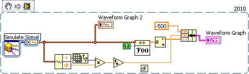
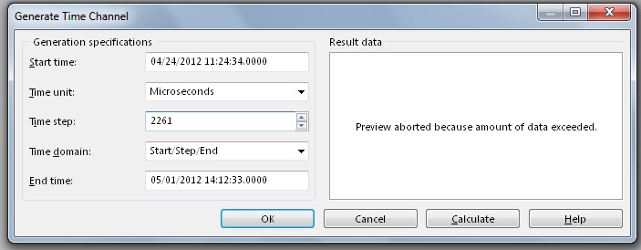
I've done some tests and I actually reproduced your problem to get frequency much lower than expected with the FFT. The problem is the way you build your weather channel data. ¿WHERE do you get your data points? The thing is that sometimes the data comes in the form of waveform data. This means that these data already include a channel in time in the same channel, so you don't need to generate a time warp to compute the FFT. If your data is a digital channel only, you need not generate a time warp to compute the FFT. How to calculate the time channel is given the sampling frequency of your data. For example, I have a channel with 325000 points, and the sampling rate was 50000Hz. This means that I have to generate a time with a stage of 20 channel (1/50000) in order to obtain a measure of the FFT of 25000 Hz. If I use a stage of 20 with a selection of field time/Step/bib and 325000 as number of values in the window generating weather channel, I get the channel early to use with my data to compute the FFT. In your case, your sampling rate is 12800Hz, which means that no time should be 78.125us in order to obtain a measure of the FFT of 6400 Hz. In your post, I noticed that you have a different time step. On the other hand, you say that you get a total of 4757810 data points. I do not understand how you get this tip with the sampling rate interval and the time you mentioned. I suggest you create a weather channel using the stage early and check that the data points total is correct. You can use a string of hour or a digital channel, it doesn't really do much since you get the same result for the FFT. I hope this information is useful. Don't forget to post back if you have any questions.
See you soon
-
Hello everyone.
I'm having some trouble for my project.
I would like to apply the Fast Fourier Transform on data acquired by an accelerometer. I do measures of vibration, data entry is a string it is then cut into the values of the axis 3 and converted into numbers.
What I would like to make is the FFT of these data, but I don't know how to "transform" waveform to apply the transformation.
Any help is appreciated.
My VI, commented, is attached.
Dear AndreasSchnaas,
Try the "worksheet to an array of strings.
To enable a detailed response, record the value by default in your orders and indicators data and post your VI once more. Data can be collected using your VI, unless the equipment is available for the user.
See you soon,.
-
DSA 4461 FFT on both channels simultaneously
Hello. I use card PCI 4461 DSA and am currently power density measures (FFT) on both channels simultaneously.
I found the example of the case acoustic and vibrations, but it is only for a single channel.
How can I do to measure 2 channels? I have to add a channel more 'DAQ - mx create a channel' vi series?
I don't know how vi DAQmx REad it would handle. I have had 2 channels for voltage using Express VI.
Thanks to Labview 8.2
Thank you
I advise to use extensions on your DAQmx task to select multiple channels. When you select the physical channel, choose Browse and a list of all available channels will be filled. Hold CTRL and click on different channels to add to your task. See the attached pictures if you have any questions on how to do it.
You can choose to display these data on a single waveform chart, or you can split the signal and analyze each channel separately. Try this and see if it works for you.
-
Creation of 1 d-Array permanently FFT
Hey guys,.
Im making measurements of vibrations with an accelerometer on my mydaq. I already get my timesignal reading properly. Subsequently, I record these readings in a 1 d table. Now, I want to achieve a FFT spectrum.
But the illustrious FFT's are useless, they do not display something useful. I tried before to take a FFT is the express.vi and it worked perfectly. Has obtained Spectra as normally and worked well. But as Im not allowed to use the s express.vi in my project I can't use it.
So, any help would be very appreciated Im getting nuts with him and Im trying to get this race for 3 days...Thank you very much
LabView 2014
Configure the Read DAQmx for samples of N. reglez_ to return a data type of waveform. Connect to your fft function.
-
Hi, I know there are several ways to perform the fourier transformation in LabVIEW, but I don't know which one to use correctly.
I have a signal that is in the table and I want the signal analysis using the Fourier transform.
I tried the Spectral measure Express VI, Power Spectrum.vi, power spectrum of FFT PSD.vi, .vi spectrum FFT (Mag Phase)and FFT.vi (do not know the correct size of the FFT to use here, I just used 128).
Which should I use?
Thank you!
Bob,
Try to remember that without students, you would be unemployed. Interesting that all the answers so far have been people with extensive experience in academia.
JersonJose,
After looking at your last post, it occurs to me that perhaps to extract the Information.vi to your unique might work for you too. To use it, you need to create a waveform from your data that I described above.
Lynn
-
Detection of overruns of vibratory limit with FFT
Hi all
We follow a piece of rotating machinery for vibratory limit overruns. Our acquisition of digital data is running at 3333Hz with anti-aliasing in front of the ADC analog filters. We sample at least 5 times on the highest frequency of interest. We then duplicate the measured data and apply several sets of filters band pass to divide the specrum in several frequency buckets watching us then for exeedences the limits defined.
We head to dedicated hardware for our analysis of the frequency of a solution all digital. I have a display FFT showing the linear magnatude of the signal over the frequency. Then, I want to implement limit control on the output of the FFT for real-time tracking. We will always post our data in frequency bins and will have a second look to limit cost overruns after the fact.
As most seems, I had trouble doing exact enough amplitudes of the FFT. Not sure if my problem is spectral leakage or a total lack of understanding FFT. I think it's the latter.
My sample VI has a capture of dynamic data with a real overtaking in the bandwidth of 4-50 Hz. The limit is 5 across. Amplitude in this bandwidth was almost 10. I've included a screenshot of exceeding the limit on the face before of the VI for reference. I have also indexed data saved to the point where the excceedence is visible on the raw data.
I tried using a FFT to visualize this limit so that I can detect the overflow, but I have not been successful. FFT tried several methods and all do not reach the height. Those smarter than me could give it a try? I don't want to run multiple filters of past band by signal in real time, as we do post-processing. I am trying to monitor and display data between 8 and 24 channels. I am concerned about the limits of my processing power to stand in a real-time environment close.
Thanks for the help! And I would like to know if it's just the misapplication of an FFT and if something is better in order.
-Chris.
Lynn,
Thanks for the reply! I tried the inverse FFT road as well, but my implementation was nowhere as clean as yours. I had to spend your complex 1 d inverse FFT block to match the data source however. The actual parameter was twice the amplitude of output. Update attached VI.
I like this solution and you will use Fortunately!
I have an another question though. My company uses not rms. All our limits are in peak (peak-to-peak) / 2. We can also assume that all the waveforms are sinusoidal and so impossible to convert from rms to crete with a root of 2. I'll need a FFT function that does not export in rms. In Matlab, our guys had to code our own FFT function as rms output all built-in functions.
Any ideas on where to find a FFT function that does not export in rms? Annoyingly, I need then inverse FFT in rms as well to match.
-Chris.
-
The size of the FFT unexpectedly affecting maximum frequency
I was playing around with the Labview Signal Processing course manual exercises (NOR, 1997), when I came across the unexpected result. I have included below the block diagram for exercise 3.1 (one side FFT) of the manual. This demo vi had left the size of the FFT (by default). I don't know what is this default value. It is not stated in the context-sensitive help. I tried to add to the size of the FFT. Unfortunately the FFT analysis did not give a precise answer, when I put in the size of the FFT. For example, I set the frequency of the 100 s, Fs 300 Hz sinewave and non of the sine wave 500 samples. When the FFT size has been set to 256, I get 2 to 51 and 102 Hz frequency peaks. The size of the FFT of 512, I get a peak at 102 Hz. 1024 of the FFT size, I get a polymorphic waveform!
However when I put the size of the FFT-1 so I got the correct peak at 100 Hz. I guess that's the default size FFT. I could also get the correct TFF frequency, if I set the size of the FFT (500) to the same value with # no samples (500).
Is there anyway I could set the FFT size and still get the correct output of the FFT. Thank you.
This was recorded for 2011.
-
Help with fft vibrations without using the package of noise and vibrations
I'm looking for help in the analysis of vibrations. I use an example updated NI 9233 VI, to get a signal from the accelerometer for display using a FFT power spectrum. I'm not entirely sure if it works, because it's the first time I've ever done vibration analysis on LabView. So if you could explain a thing or two about vibrations or TFF, I'd be more than willing to hear from you. I have included my code along with a photo of an analysis of vibration of the computer, I work with. (even when I don't know if his work that I just thought it would be good to show an output)
Brandon
Data sheet:
I have LabView 2011
I FPGA, real-time
I have a model of research of Wilcoxon accelerometer 797-33
With an NI 9233
On a cRio-9012
Hi Brandon,.
You can use the FFT Complex (photo attached) to calculate the magnitude of the acceleration at different frequencies. You will need to take a little further to build a new waveform with this release, which includes d0, df and the output of the FFT. In order to calculate the df, please refer to the user manual on page 10-3. With respect to the scale that is output by the FFT, it must be same as input. Hope this helps to answer your questions. Thank you!
See you soon,.
CARISA Leal
-
I'm figuring the FFT of several signals, I have used sine waves in the attached vi to highlight my problem.
I created 3 sinusoidal signals using signal generated express vi.
Sinusoidal signal 1: Fs = 20 Hz
Sine wave 2: Fs = 250 Hz
Sine wave 3: Fs = 500 Hz
I combined these signals in a table and fed in FFT Soectrum (Mag Phase) VI and see the results on a graph in the form of wave. I changed the property of multiplier of charts to the sampling frequency of the singal handset (1 sine wave Sine Wave 2 + Sine Wave 3) which is equal to 770Hz.
The plot of the FFT spectrum is throw up quite unexpected results. I expected peaks at 20 Hz, 250 Hz and 500 Hz, but I get crazy values.
I'm doing something wrong... ? Take a look at the vi attached please.
Stroke
Hi the shots.
You seem to be missing a few basics about LabVIEW data types as well as their manipulation...
You cannot add waveforms by adding berries to Y in a larger painting, you must Add the.
Play with the filter command in the attachment (to perform a control of it can make it easier...)
-
Cannot write the FFT of the integrated double data
I am a beginner to Labview environment.
I have acceleration Vs time dat file .lvm
Can I get the double integration of this
acceleration data for trip data.
Can I get FFT of displacement and displayed on the graph.
Up to this point VI works
But now if I connect this FFT of moving to 'write the measurement file' then it displays error.
Please help me... and correct the error... All I want is two column data, frequency andthe other of the amplitude of movement.
I have attached all files
I ask you to correct the VI please...
Thanking you!The concepts that you'll want to research are"matrices", "indexing of tables", 'automatic indexing', 'cluster' and 'type of waveform data'.
The loop IN the first VI I sent used the automatic indexation to take each element of a table 1 d of the clusters and perform operations on them separately to convert them to a waveform. Exit tunnel also uses automatic indexing so that the end result is a table 1 d of waveforms. I used the loop, so that no matter how many items appear in the table, you get a corresponding number of signals to the "writing on a file of measures."
In this case, because the output of the FRF is a single cluster (and not an array of clusters), the loop FOR was not necessary. The VI attached this time takes the output of cluster of FRF and maps the cluster to a single components build the wave function and you get a result of unique waveform.
I have no sound and Vibe loaded on my computer at the moment, so I can't run your VI and see the result of the integration of the snout to the Cloaca VI. The output data type is "Table 1 d of waveform" and your indicator and your two FRF can accept only waveforms. I put a function between integration and the indicator/FRF array index, but if there is more than one waveform in the table, it would be the wrong solution. My solution corrects the broken wires but throws waveforms 2,3,4... If they exist.
-
How to find the ratio between the two frequencies in the fft
Hi, I'm Jean,
I need to find the ratio of the frequencies of 1st and 2nd graph fft.
Already, I received information of this site only. Mr. Alten helped me.
Now, I have to continue the same problem and need to find the ratio of the frequencies.
Please someone help me guys...
I will attach my vi file and the text file.
John,
Should you report the frequencies or the report of the amplitudes of the components at these frequencies?
The Information.vi of your multiple for the Signal Processing, extract > range of measures of waveform should do what you want.
The frequency resolution is not very good because you have cycles relatively little waveforms (2 ~ for the lower frequency). I added a few zeros to improve resolution, even if a larger sample of data would be better.
Lynn
-
FFT vi truncate the FREQ of signal.
Hello
I noticed that the FFT vi truncate my signal. See attachments.
I'm basically the noise of a signal (I have both the phase - I - and out of phase - Q-signals...)
(Ignore the vi curve, it is just to remove the continuous component of the signal, it's irrelevant to this discussion).
Kind regards
Ali
You lose your calendar information for data going to the graph of the PSD. It works on arrays. The FFT functions assume a dT or dF 1. So when things are placed in the chart, you will see values up to 0.5 since Nyquist limits you to 1/2 of the sampling frequency. PSD2 graph doesn't have this problem because the blue wire of the DDT keeps the calendar data.
If you build your table in a type of waveform data and the boot in the value of dT, your data should look like the other graph.
Maybe you are looking for
-
MacBook Pro lights at room temperature.
Hello I had this problem with my late 2008 unibody Macbook Pro since last year that he only turns on when I use a blow dryer and blow directly to the logic board to increase its temperature to above 70 ° c/160 degrees Fahrenheit. I only found on this
-
I can not get a script Perl - the compiler will not accept even the quotes
-
Prohibitory sign on compressor in El Capitan
Why is my system tells me iHave installed when 4.1.3 iHave 4.2? FCP & Motion all two open fine but compressor continues to tell me it is exceeded when well even I deleted 4.1.3
-
I can print is more than a Web site. I can in other browsers, but not Mozilla. Help
I used to be able to print any time I had to. Printing became so small that I couldn't read. Then the pages I printed out from the website, printed white pages. I contacted Thunderbird because it was first noticed on email when I tried to print somet
-
Windows 10 not settle on Satellite P850 - 31L
Toshiba satalite P850 - 31L will not be updated to windows 10, I've updated to not win 8.1 clean install No 10 windowns Update icon in the status bar and I also tried iso it says that the code is wrong? any help please