design and simulation of control tools
Hi all
Does anyone know if indexing is possible in a loop control and Simulation in Labview? I need to save to a table of all simulation data.
Thank you
Ussr123.
Resolved: the required icon is called: collector.
Tags: NI Software
Similar Questions
-
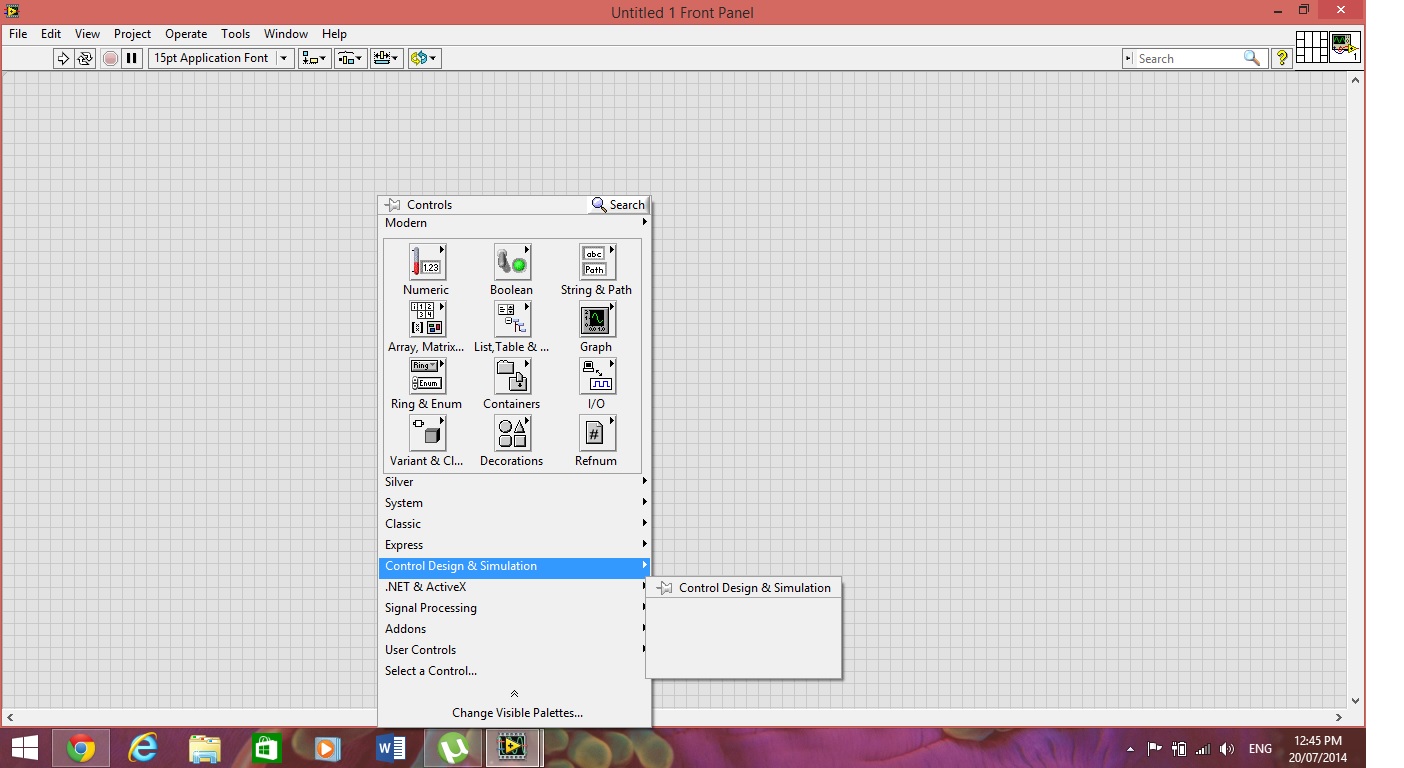
There is no tools in the control design and simulation its Blanck
There are no tools in control design and simulation its Blanck. I saw the same question asked before and found a solution that, if we install 32-bit labview then all options will be available. I installed labview of 32 bits, but the result is the same. Please help me thanks in advance...
So yes, I think that it is possible to use this tool as a trial.
but you have to install after installing LabVIEW.
-
Control design and Simulation palette is not displayed
I'm using LabVIEW 2009 professional degree. I installed the Control Design and Simulation Module with its other tools required. The problem is that Control Design and Simulation palette does not appear in the Palette of functions in any VI. Please help me with this.
Adeel Amin
NED Université engineering & technology
If you run the License Manager, expand LabVIEW2009 > Modules > Control Design and Simulation.Can you make sure you have this directory and what is the color of the cube just next door?
-
Space required on target RT for LabVIEW Control design and Simulation
Hello
I want to run a DLL file on an RT target using LabVIEW Control design and Simulation, but I'm not sure of the required amount of RAM on the RT-target. My RT-target options are respectively cRIO 9002 and cRIO-9004 with 32 and 64 MB of RAM. Is this a sufficient amount of RAM to run the simulation? ¨¨
Thanks in advance
This will depend on the size of your dll, the size of the rest of the code, you can create other necessary drivers/modules, memory use when your application runs, etc.
9002 and 9004 have not a lot of RAM on them and the minimum software installation to run a control application Design & Simulation (CD & Sim) will take around 22Mo of it (the majority of RAM available to the 9002). It would be possible to run your application on these two controllers if you keep it small but it will depend on what you want to do.
-
Live PID missing under Header Control Design and Simulation
Hello
I have currently the full version of the University of Labview 2009, but the PID screws are missing. I understand that they are under Control Design and Simulation, but there is nothing in this topic. In addition, an image of my license manager OR is attached to show which is enabled. Any ideas?
Thank you
The PID toolkit is part of the Developer Suite DVD.
You have the following Professional Developer?
-
Control Design and Simulation Tutorial
Hello
I begin with a course that requires the use of the Control Design and Simulation functions. Before asking stupid questions, I want to see the hand on the tutorial, it is referenced in this white paper.
http://www.NI.com/white-paper/5855/en/
However the link to the tutorial ftp does not work, someone else has an alternative link, or could buy the tutorial directly.
I appreciate any assistance.
Kind regards
Danny
Try again... Earlier, I was able to download the zipped file
-
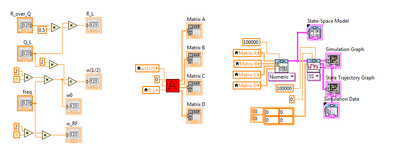
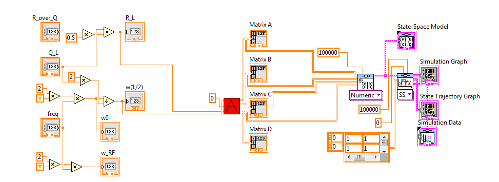
(Control design and Simulation) State-space block don't gives result
I tried and tried but failed to get the State-Space block module to give me a graph / output.
I have no idea what the problem is and I hope someone can help me. Numbers and calculations work in Matlab (Simulink) but I can't simulate in labview.
Anyone have any ideas?
The problem is that you are assuming that LabVIEW runs left to right. Stream does not work that way. Your code like this:
does not say LabVIEW He must run everything from left to right. What happens is that it runs to the 3 'island' of the code in parallel and, in this case, it will be "empty" values You must remove the local variables to do this job and paradigm of data flow runs your code from left to right, as you wish. Here is the code:
Also, one last thing. Your contribution to the Simulation of the 'linear' CD is equal to zero all the. This means that you try to input zero linear system, which will give you a result zero in the answer. You probably don't want that since zero as input gives you more information. If you want to see how system will reset after initial conditions, you must use 'CD Initial Response. " Or you need to change the input to the system signal. Please study this shipping example to understand how to use the linear Simulation and initial response:
C:\Program Files (x 86) \National Instruments\LabVIEW 2012\examples\Control and Simulation\Control Design\Time Analysis\CDEx time domain analysis
I hope this helps...
-
control design and simulation in a loop the final amount not what I expected
Hi the LabVIEW forum members.
I have a frame control and Simulation in which I am simulating a regulator in closed loop (see file attachment). When I apply a step of the input unit that I expected to get the answer to deposit at the unit, i.e. the stage of entry being the set point. However, he moved to about 0.625.
Can someone point me in the right direction please? I'm obviously doing something wrong here.
Kind regards
OK guys,
Cancel my last post, I found my mistake, it was the P + I control shape, I made a mistake in the Integral control action transfer function where the Integrator not arrive to integrate an error.
Kind regards
-
How to make my waveform in the simulation design and control work continuously?
Hi all, I m a begineer to Labview and have a few question.
I use the Labview to design and implement a controller for FOPTD system, but I found that the waveform in the 'loop control and simulation"does not work continuously. I mean keep repeating in the same graph from 0 to 10 seconds. Is there an approach to make it run continuously?
Thank you very much.
Whenever a loop Control Design and Simulation is executed, it connects a full simulation, the initial time for the last time. When you drop a new loop CD & Sim down, the default values are zero second initial time and 10 seconds for the last time. I guess what you probably want is for simulation do not stop at 10 seconds. Double-click the left node attached to the CD & Sim loop and extend the end time. You can change the end of 'Inf' time if you want it to run until the VI is stopped.
-
Control and simulation and data acquisition
Hello
I am applying to motor control in Labview. I'm sampling speed from DC engine in real time through an acquisition of data. (my sampling time is 1000 samples per second)
Then wrap speed as input to a Simulation (simulation and design of the order) and inside the loop simulation, I have a PID controller. The PID has the actual speed of the engine for the acquisition of data and the engine reference speed as input.
Reference engine speed comes from the generator of signals (control design and simulation-Simulation) and is a waveform.
My step in the engine size is 1000.
I am running this application real-time and drawing the reference signal and the motor real signals. I run into several problems with regard to the calendar.
1. when I change the size of the step of the simulation loop, the frequency of squares of reference also seems to change. For example. What step size = 1000, duration of pulse = 1 s. What step size = 100, pulse width = 0.1. (My pulse frequency is 1 Hz, Simulation clock - 10 kHz). How step size can affect the pulse width.
2. can you explain the relationship between the DAQ, the Simulation step size loop sampling time, Loop Simulation period.
3. If I want to collect different sets of data using sampling different hours, it's OK to change the sampling DAQ time without changing the size of the step of the simulation.
Would also like to emphasize that the DAQmx calendar under sample clock mode is placed in front of the simulation loop and the output is connected to the loop simulation.
Appreciate any help.
Hello
Maybe some screenshots of your code would help. Furthermore, what you have read your samples together with your DAQ screws?
(1) If you have a waveform, the output is specified as:
For example, if you change the size of the step of the simulation loop, you change the simulation time which are introduced into the signal generator and affecting the waveform that you see if you do not have a size quite small step to characterize the waveform that you generate.
(2) sampling DAQ rate is the speed at which samples are taken on the acquisition of card data itself. The size of the simulation step, help. "Specifies the interval between the time when the ODE Solver evaluates the model and updates the results of the model, in a few seconds." Simulation loop, still using, "Indicates the amount of time that elapses between two subsequent iterations of the loop of control & Simulation.". " "Step size determine the value of t that is introduced to the functions you use in the loop simulation while the loop simulation period controls simply to how fast you change the following t value. The sampling rate of DAQ hardware is a clock of completely separate hardware controlling the analogue-digital on the DAQ card converter so that you can get a deterministic dt between the samples being acquired.
(3) you can change the schedule for the acquisition of data, but you will need to restart each time the changes take effect. If you change the calendar of data acquisition and want your values to correlate with your simulation, you will need to change your size of step as well.
-Zach
-Zach
-
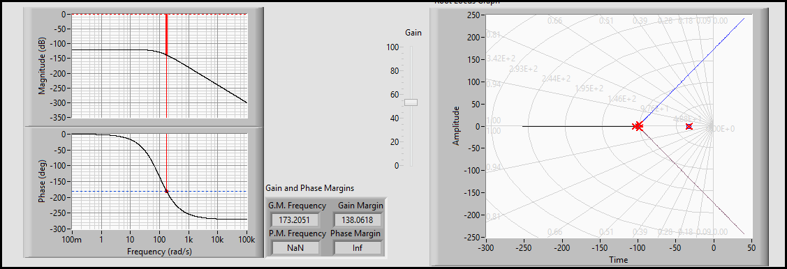
I just installed the evaluation version of LabVIEW and LabVIEW Control Design and Simulation Module 2013. Normally, for the design of command I only use Matlab/Simulink but LabVIEW has some advantages and I want to enjoy these benefits. The problem, I think it's boring, it's that I can't use the money controls to change the default control style classis - like bode gain and track of lotus of margin or root below phase
Hi muahang,
Why not? What is the problem here?
These plots are like XY graphics standards (maybe with graphs from bottom fantasy for the locus of the root)...
-
Control and Simulation in a loop / while loop with TCP/IP reading / writing of synchronization
Hello, I have a problem with reading TCP/IP and written in two loops. The problem is NOT to get the two loops to read and write to and from the other. This has been accomplished. My problem is when I run control and the loop simulation on my laptop and the while on a RTOS remote on the controller on-Board of LabVIEW in a remote PXI chassis, the while loop the remote system running on four 4 times faster than the loop control and simulation on my laptop. In other words, for each iteration of the loop control and simulation on my laptop, there are 4 four iterations of the while loop on the remote system. I need to know how to get a degree of kinship (1:1) with these iterations of the loop. When I run a longer simulation in real time, say 10 seconds, the control and Simulation loop begins to slow, i.e. the simulation time slows down until it is no longer in real time and the "Late Finish"? Parameter is set to true and the LED lights and continues to stay lit. At this point, the system destabilizes due to what I believe is being well sampling rate too discreet and I have to end the simulation. How can I get a ratio of one to one between the loops and also to avoid slowing the loops causing destabilization?
To give an overview of my application, I implement a control system in a network, seen in "image2.png". This is achieved using my laptop as a subsystem 1. Reference signals are generated from the laptop and the error signal is produced. Control measures taken and the control signals are sent via TCP/IP to the remote system. Position feedback is returned, and the process repeats. My system has Core I7 Procs w / 3 GB of RAM, up to 1 GB/s speed via ethernet and LabVIEW 2011 installed with all necessary modules and networking tools. The attached VI Custom_Wireless_Controller works on my laptop. The remote system I'm working on that has the 7830 NI R Series with FPGA card. OTN runs on the PXI chassis with an enbedded controller that has networking capabilities of up to 100 MB/s via ethernet. I use the FPGA for the acquisition of data and apply control signals to my plant. The plant is the PCE twist connected to the FPGA through the cable of the ECP - RIO of NOR. Subsystem 2 is this side of the CNE. The FPGA collects position, he sends to the controller via the network, receives signals from the network drive and writes signals to the plant power amplifier that operates the plant. This process is repeated and the VI and is titled Custom_Wireless_Plant.
I appreciate the help really and look forward for her and for any question!
Well, the first step is to understand what you have set up right now. Your control and Simulation loop on the side of the controller is configured as 'Runga Kutta 4' and you have a loop timed on the other side. In addition, you have the primitives of TCP/IP on the control and the Simulation diagram and means he will perform (a message) on the size of each minor step, which in your case is 4.
So, you have two options:
1. replace the Solver side controller Runga Kutta 1 (this must synchronize loops)
2. hold RK 4, but create a Subvi around two primitives of TCP/IP and configure from the VI to run than the major (continuous) step-size. If you do it right, you should see a 'C' on the upper right part of the VI you have created.
Please let me know if what I said is not clear...
-
loop control and simulation: sync settings
Hello
Is it possible to access times higher at 1 kHz source in synchronization settings, control and Simulation in a loop, without use of real-time targets? For example, using time cpu.
I use myDAQ OR data acquisition, and I need a 100 kHz synchronization source about.
Thank you very much.
Kind regards
Keshav
N ° when running on a PC of the class, you are working with a set of standard material (with its clock 1 kHz) and a non-deterministic BONE, and there is nothing you can do about it. That is why acquisition cards NOR are all smart devices with their own processors, memory, and clocks.
Mike...
-
control and simulation Module spring mass
I'm using Labview 2010, and tasked the simulation module (just 15 days before the date of expiry. trying to see if the program will work before I spend $4 K) and try to calculate the dynamic response of a spring index.
I was able to complete the program in the simulation section (I think). I now need to feed a sign of acceleration in the module which I have already captured at a sampling rate of 100 k/s.
Test technician said I should add 500 ms from zero to the front of the track to make sure that the system is stable before the trace of acceteration of power is in the simulation module. I have alreay done reading and adding zeros to the chain.
I can't feed the trace in the module control and simulation.
The engineer said he was able to do the math in MatLab and simulink (I think), because I have not used this program and we do not have a copy I am doing it in LabView.
In addition, I would add that this forum is blocked by my firewall to work.
If you need more information, I'll have to return to work and get it.
-
Problem control and Simulation
I worked in the module of control and simulation of NI Labview 2013 and created a VI as indicated in the attached file, but I don't understand the output of VI.
I applied a progressive input signal to device to transfer function = 1 /(s+1) and the desired output (exp (-t)) appears in green color (drawn by me in MSPaint) but it displays the output as one shown in red color.
As the inverse of 1 /(s+1) Laplace = exp (-t), the graph must be a value of 0.3678 at t = 1 and 0 to t--> infinite but the (red) output is exactly opposite.
Can someone explain please exit this is why it is like that?
Concerning
When you apply a step response, you must multiply your transfer function of 1/s to account for the progressive input signal before making the transformation from Laplace to get the correct result. In your case, the transformation gives: (1 - e ^ (-t))
There are many explanations of answers online, but here's onestep.

Maybe you are looking for
-
Why my iMac 4K (late2015) runs so much slower than my MacBook Pro 128SSD (end of 2012)?
Both are basic model, without Add - ons or updated, the new iMac, retina display 4K runs as slow as some laptops HARD drive. What is the defect of manufacturing for my iMac? Any idea? Thank you.
-
Latast Skype c7
-
How to convert an image to grayscale 8 bits unsigned 2D table
Hello. The "Color Utilities' Vision Development Modulde function contains the ColorImageToArray IMAQ, who only has the 32-bit unsigned integer as output values. Y at - it an option to reach a value of the integer not signed 8 bit at the exit?
-
Hello My name is Karen, I just got a new monitor used, but when you turn it on, it turns on, but then you can't see something that he disappeared and in the middle of the screen it says u can not display this video mode, your help would be great than
-
Not able to access the website of the Bank, he returned to the home page.
Original title: EXPLORER AND WINDOWS 7 Can someone explain this: I am running Windows 7 and 9 of the Explorer If I go to my Bank's Web site and enter my ID and password the screen turns to the empty connection. I blame myself for a sloppy set - up Ba