details on the test of suspension of vehicle (car) with labview real-time
Hello friends,
I'm doing phd in the suspension system active semi auto. Here, I need to study and measure all the setting of suspension of the complete vehicle experimentally. . So far, the experimental cost is so high.that too will give the approximate result.
In the experimental method, we need create the profile of the road using jacks. Its cost too much. I don't want to do that.
I would like full of model.is of vehicle it is possible to time real suspension test using labview? Let me tell you what I want.
I have to fix four sensors on four wheels to measure the road disturbance. Then I will join four more sensor on the car body.
This difference in two reading will give the perfromace of my suspension. Whenever I drive my car, I can get this place profile and the road to the deformation of the car body. Finally, I can measure my performance of car suspension.
is it possible to get the upward movement of the tire by using sensor in labview? That's what I want exactly. In the experimental method, we spend a lot of time and money to create the profile of the road. but it is already available in envirment. So, I just want to eliminate the road profile. If we eliminate we can easily measure the performance of the suspension.
The measured value recorded in the vehicle itself using labview computer. So we can better the performace.
If you do not understand my question pls ask me once again.
looking for your answer.
Spengler
I saw an article that uses labview for quarter car model. but want to do it for the full car model.
Hello
I hope that I can understand what you mean, because I did several tests on vehicles and I hope that I can tell you something good for your topic.
First of all, I am interested in what kind of upward movement? Speed, displacement or same acceleration? You can have a lot of possibilities for a test in the vehicle using LabVIEW, CompactRIO or CompactDAQ, but they are all software problems. If you know which parameter you will measure, we can simply fix the sensors on the suspension and run the test program.
Also you can collect the State of the car, for instance a speed of ROTATION of the wheels and so on, through the CAN bus.
If you are you doing PhD on this topic, you may need to find a company to present a better solution. Well, in a Word, it is a part of a doctoral thesis.
Wilbur
Tags: NI Software
Similar Questions
-
Application errors of the RT with the PXI-4461 with Labview real-time 9.0.1, DAQmx 9.0.2
HI -.
I recently converted a PXI time system real OS (PXI-1042 q chassis, controller PXI-8187, DAQ, PXI-4461, DAQ, PXI-6259). I can write and run DAQmx applications in real time with the 6259 very well. Whenever I try to write a labview RT app to use the 4461, however, it will fail. Note that I can use two cards through MAX I tried switching card slots, just in case it was a problem. Both cards worked with labview, the PXI chassis was before Windows.
Attached are pictures of the screw base demo I built to show the problem. Since I was a mistake (-200758) if I started from the raw strings, I tried to create a MAX task and use it. The task, but he complained of a buffer is too small. I explicitly put the buffer to work around this problem and still get the same error (-200608). I've also attached a screenshot of the software currently on the Max MAX RT PXI system is version 4.6.2 btw. (I installed the most/all this from DS1 Dev Suite 2010 version).
Please let me know if I hurt something installed, versions if 4461 just don't play nice with the new BT or RT software, or if something is wrong. Thank you.
Kregg
The first error you see is (details in the help-> error explain in LV)
-
Read file test.txt (binary or what?) with LabVIEW 8.6
Dear friends!
Please, how to read the attached file (test.txt) with LabVIEW 8.6. In the same VI, can I convert it in a txt file real with the results presented in the rows and columns? Please, any idea? I need help!
The rebooting of the trace file is binary.
Unfortunately, without a description of the real file by developers RELAP format, I don't think you are going to get very far on the decoding of the file.
You must get directly in contact with the authors RELAP.
Here's the blurb to the RELAP Manual:
3.1.4.2 the reboot-Plot file.
The restart-trace file contains almost all the parameters of calculation
(Sub fractions, pressures, temperatures, flow rates, etc.) for transient computing together.
A common misconception is that a parameter must be specified using a minor in change request
in order to be available in the reboot-trace file when the calculation is complete. Affects a minor change request
only the printed output. The restart-trace file is accessible repeatedly that the new data should arise. However,.
during a calculation, the data are written to the reboot-trace only for minor editing file (and the plot point)
frequency. Once a calculation has been performed, it is not possible to recover data between data
written to the file to restart-track of the points. Therefore, it is important to choose a minor edit (and plot the point)
frequency that provides the plot to an interval appropriate to the problem is resolved. In practice,.
the minor change (and plot point) frequency must be changed during the calculation as the product of the problem
from one phase to the other. Common points must be selected in the phases of problem where rapid
RELAP5-3D/2.4
INEEL-EXT-98-00834-V5 3-18
setting changes are expected. For the economy, less common points must be selected in the phases
where the conditions of rest are expected.
Calculations are usually made using several reboots. (See Volume II for the restart entry
requirements.) For example, a new problem runs from 0 to 10 seconds. This first part is analyzed and
Run again from time zero that errors will be corrected. When a managed to 10 seconds has been calculated, a
restart run is made (for example, 10 to 30 seconds), and so on. RELAP5-3D
© offers you the possibility of
change of almost any feature of the model at any point of restart. When changes to the model are incorporated on
reboot, reboot-plot file reflects those changes only after the decimal point in the calculation, where they have been
implementation. In the example above, if an injection system is added to the model to 10 seconds, then data
for added components exists only for the time after 10 seconds. Changes, deletions and additions of model
are constantly being implemented. If a model change is done in 10 seconds, the revised model remains in
effect unless other changes are made to subsequent restart points.
When a calculation is completed, the restart-trace file becomes a valuable document of the
calculation. If lost, replacement would require reperforming the calculation, usually to the considerable
loads. At a later date, the file can be accessed and previously compressed data can be obtained as
necessary to extend the analysis. Therefore, it is recommended that files of restart-track of the important calculations
be protected safely and permanently.
-
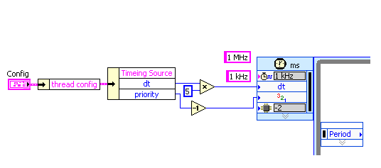
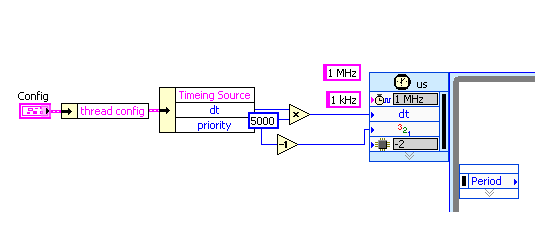
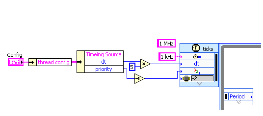
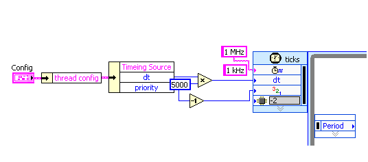
"1 MHz" for the name of the source on the time loop does not work on LabVIEW Real-time 9.0
A Loopis Timed running as expected if a time source is manually chosen in the dialog box of configuration for "1 kHz" (first digit) and "1 MHz" (second digit). If the time Source name is set through the input of the channel "1 kHz", the loop is executed, too third figure). But if the input string is "1 MHz", the loop is not executed (last figure). The channel two are created by "create constant" on the entry of the loop to exclude typos. Is it possible to set the Source of a loop time timed through the input string to the real-time clock hard Mhz?
OK, I was a bit confused by the difference between the behavior of error...
Now, the question is quite clear. Aid for the timed loop provides the following regarding the Source of the calendar entry:
Specifies the name of the synchronization source to use to control the structure. The source of synchronization must be created using the create synchronization Source VI on the block diagram or selected in the dialog box Configure the timed loop .
So, I think that you have somewhere in your code a time Source.VI create if you pass "1 kHz" as the name. But you did not do this for your clock "MHz 1"...
hope this helps,
Norbert
-
How to make the variable data record (intermittent time), with a real-time display
I'm a complete newbie to Labview. We are currently developing a piece of hardware in the lab to automatically take the readings of the concentration of a sample, through correlations with voltage readings. I have read and worked through the getting started with Labview .pdf, but other than that my knowledge is minimal. I have a flowsheet of work who is able to do it correctly and display and write the data in real time. However, I want to be able to write to a file only every 10 minutes or so, since experiments can run for several days and the amount of data it currently logs is unnecessary.
Would be nice if he could write it in columns like this:
[date time] [voltage ave] [levels]
xx xx xxx
xx xx xxx
xx xx xxx
.. .but only once every 10 minutes. Or at any interval of time, I put.
I tried to connect different parallel loops, but I failed miserably. I don't know if it is a relatively simple problem for you guys to help me with.
I have attatched file. Please note that the file variables.txt is there simply to hold the settings for the correlation of concentration, which took charge of him.
In addition, advice or tips to improve this would be greatly appreciated.
Hi mooray.
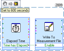
I took a quick look at your code, but you should be able to do something like this:
When you have an Express VI elapsed time set to 600 seconds (10 minutes). If every 600 seconds time out will pass a Boolean TRUE, which will allow to write the measurement file Express VI. Therefore, what iteration of the while loop, you would write some input comes in the signal input to write it into a file position.
There are other ways to do this as well, but it's pretty simple. I hope this helps!
Thanks for choosing National instruments.
Aaron P
National Instruments
Technical sales engineer
-
Should I use the Filter SmartScreen with MSE (with enabled real-time mode) together?
I am running Microsoft Security Essentials in the real-time mode, however, I wonder if it's enough. I have also enabled the smartscreen filter or MSE already covers who?
I have both, would allow unless it makes your computer run slowly. In this case, just activate time mode real MSE.
-My opinion-You must upgrade your browser to Google Chrome and install Comodo Internet Security. Better security and performance for your PC :D -
How to define the details of the White Balance metadata Bridge Cs6 shot with 5 d MarkIII?
Is it possible to get detailed information of the White Balance setting in the bridge metadata? I get only "custom"; My instructor at the College needs more detail in my contacts boards.
Thanks for any imput
Is it possible to get detailed information of the White Balance setting in the bridge metadata? I get only "custom"; My instructor at the College needs more detail in my contacts boards.
Thanks for any imput
You can't get this info in a Board-contact, nor is it easy to get other then look at the setting of the device you used to shoot files. Maybe it's somewhere hidden deep in the exif data, but I can't find it with the exact number.
Shooting Raw these WB figures do not apply because you can adjust the color temperature and tint to what you want. Taken jpeg, your options are limited due to the fact that the raw data is already processed and the evolution of the effects of temperature and color of the entire image.
Try to shoot a Raw and jpeg together from the same scene. The one with the light of day and the other with artificial light conditions. (personally, I put my WB set closed at 5,500 but with the auto settings, you can also see the difference) Try to fix the jpeg and Raw file in ACR and see what I mean.
And to be honest, if your instructor at the College would like to have what he should tell you also why he wants to and how you can put it back...
-
If I download the update for firefox I have problems with my real player as with the last update?
The last update for firefox I was warned that if I downloaded it that my realplayer wouldn't work. I don't want to download the update to firefox 6, if I'm having a problem with realplayer
Using the RealPlayer Plugin with Firefox
- https://support.Mozilla.com/en-us/KB/using%20The%20RealPlayer%20plugin%20with%20firefox
- http://KB.mozillazine.org/RealPlayer
Check and tell if its working.
-
is there a field type in the apex where I can display a clock? real time?
I just want to be able to make an application log when I can view the clock somewhere in the page.
Hello
Use the plugin to the APEX.
Demo and documentation of use is inside the link.
-Sunil Bhatia
-
NOR-DAQmx compatibility with the system in real time
I try to use a time system 11 with LabVIEW Real-time. When I try to connect with the driver OR DAQmx, an error saying that the version of the NOR-DAQmx drivers are bundles with the one on the real time. I tried to use different versions of the NOR-DAQmx drivers that are available in the table of compatibility, but not those who worked. I have an old computer working with the same real-time system that uses LabVIEW 9 and has the driver NOR-DAQmx 9.3.5 f0 driver installed on it but I can't find the drivers on the web. What should I do?
I am using LabVIEW 2015 in my current computer.
Thanks in advance.
Looks like you can just have a lag in the versions of software installed on your host computer and the target. In order to deploy the code from your host to your target, the two must have corresponding to libraries of functions. See this link for instructions on updated versions of the software on your target match those installed on your host computer, the wizard of the LabVIEW RT software. If you have already done this, and it did not help, please provide a screenshot or error code of the message that is to appear.
-
Dialog box to open the file on the target in real time
It is possible to load data from a file on a local PC to a VI runs on an RT target? I have a RIO OR the VI running on. From the front panel, I want to be able to click a button and have a dialog pop up where I can choose a local file to load data from. The problem is that when I try to use the spreadsheet VI load data it returns an error indicating that the dialogue has been canceled. If I use the express VI from file dialog, the VI will always return true to cancel. The dialog box never appears. It is not possible to open a local file to a VI runs on a real-time target?
Jon VT-
This function will not work in time real (RT). Please see the bulletin 2S9D21OH knowledge base: creation of a dialog box file for use with LabVIEW Real-time for more information on this. However, it only locates the files on the target of RT. If you try to communicate with a file on your host computer, you can be forced to transfer this document to the target of RT, or implement a different architecture for this task. I would also add that given the user to define the source of the file manually create non-determinisme within your system. Again, it is perhaps another reason to implement a different architecture.
-
I want to generate a second report to the test.
I have a test setup that runs production units and generates reports that I have defined without any problem. Now, it is desirable that I create a report 'summary' as well. So I have the original report that is generated with all the details of the tests that were performed. Now a report that essentially shows what tests have been performed and the State of success/failure of each only be generated. I know that I can go and do the writing of this article to an Excel spreadsheet or something similar. I was wondering if there was a native way of the test bench it could be done first.
Thanks in advance for any help.
Troy
To create the second report, go to configure-> result processing and click on the ' + '. You will be able to modify your second report as needed.
-
Requests for details of the seller for a Min Max
Hi all
When Max Min trigger interface requisition lines, we must get the seller details also filled.
This has put in place to get these. Because when I run a Min - Max planning report, I don't get the details of the seller.
We have, in fact, we have one with one provider and the location of the seller
Help, please.OK so everything sounds good... can you confirm that created requisitions (once this audit is performed) are triggered by the execution of State Min - Max. You can check these below 2 audits
(1) type of source req will be Inv
(2) the date of creation request must match with your execution time of State mini-maxi and the item, qty should be report to article output values and Reorder Qty
-
Convert the project in real time
I started to develop a routine that (finally) will be "split" between a host PC and a remote PXI, using LabVIEW Real-time. I usually test these things on the side PC and create them using LabVIEW project. I just started a new 'project' and build first the host code. However, I simply said "New project" and got a "project without real-time targets. Is it possible to add a 'target' to this project, or what I need to start over with a new project explicitly in real time? Is the (only) way to do this by selecting new project from the main menu of LabVIEW Real-time (2010)?
Bob Schor (who should know the answer to that now...)
Bob,
All you have to do is right click on the name of your project (in the Project Explorer window) and select new > targets and devices. Select yout real-time target. From there, you can right-click on this target RT and tell New > VI, which will create a VI targeted to run on this RT controller.
There is really no such notion as "a project in real time. All projects are the same, but I suppose a real-time project is one that contains a real-time target in it.
See you soon,.
-
In time real PXI-1031 does more work with labview. "Not enough disk space to perform the backup.
The labview real-time project was working until a few weeks ago and the only error that is displayed on the PXI is this error message.
"NEITHER Configuration Manager: not enough disk space for the backup" everything before that looks like it starts very well. Recently, I removed the hard drive and remove the 4 GB network log file because it seemed to me that a file of 4 GB on a fat32 file system was probably the cause of the problem. After that it the project worked when I tested it, but others in my lab said it was broken again the next day.
Any help would be greatly appreciated because I don't know all that equipment.
I found that I had "reset IP" set to "yes" in the bios that seemed to be causing my problem because I changed it to no and it seems to work perfectly now. Sorry that it took so much time to understand and I feel like a fool.
Maybe you are looking for
-
'Sorting album' is not displayed correctly
I discovered that field "Album kind" did not work as I expected in my latest version of iTunes on 10 of widows. I added a large Cabinet in my iTunes music library. It's Candlemass band box called Doomology , which contains seven CDs each being a sepa
-
PreReqs for security on the Server 2003 patches
I try to install Windows Server 2003 KB2571621, but I get an error message saying that I need prereqs installed first. There is no information to tell me What are those prereqs, or how to find them. Has anyone else had this problem and solutions? Tha
-
Is it Possible to downgrade Windows 7-Windwos Xp?
It is Possible to downgrade Windows on a pc presario cq5300f to Windows XP? I already have a return of all drivers.
-
How do you get your E-mail synchronized with hotmail windows is it possible?
How do you get your E-mail synchronized with hotmail windows is it possible?
-
Create contacts with Aboriginal contact form
Hello. I want to be able to redirect a user (after selection of a Menu item) in the form of a 'new Contact' built-in/by default to create a contact. All the links I've read have created the contact by program I want to avoid making. Is it possible to