Development of an instrument
Hi, I'm currently developing an ARGOS dc power
I connect this device in series. I installed the drivers from NI-VISA. I created an instrument for the power driver and set up the series configuration.
9600
N
N
8
1
I'm trying to get a response from the device. I have the unit can be controlled from the outside. However, when I run the application, I get an error saying-1074003951 to complete the call in the chain then I enter the resource name of visa Initialize.vi and output volts dc vi. Is this correct?
The ID of the query failed. This may mean that you have selected the wrong instrument or your instrument has failed. Alternatively, you can use a template that is not officially supported by this driver. If you are sure that you have selected the right instrument and he responds, try disabling the request ID.
It's my first time with labview of very useful tips
Damien
Tags: NI Software
Similar Questions
-
synchronize two usb 6289 with a meter
Hi people!
I'm trying to synchronize 2 boards of the series M USB-6289 using a counter.
I searched the forum and that you've already seen the tutorials:
'Synchronization of series M with LabVIEW and NOR-DAQmx - Developer Zone - National Instruments'
'Synchronization of data acquisition USB - device to several systems - Developer Zone - National Instruments'
"The time and the synchronization of the NOR-DAQmx - Developer Zone - National Instruments features."
However, I still have some doubts (where the post
 with respect to the following:)
-If I want to use the meter as trigger for both cards do I need to export to a PFI line and connect to the Member of the Board?
-I do the same thing with the clock signal (export to the other panel using a PFI line) or using the same frequency for two meters is enough? Or both?
-can I use the same value for the frequency in the meter and two clocks?
Hope someone can help out me.
If possible, underline some examples or detachment would be great.
Thanks in advance for the help!
See you soon!
Hello
All points depend on what you need to synchronize exactly.
As you have probably already read in the links you provided, you have the option to share a trigger, or a clock, or both.
Of course, the best solution is to share together.
Then, you can choose to directly share the sample of one blade to the other clock (if the two sampling rates are the same), or to move the reference clock, then, both cards will synchronize their sample (with PLL) clock on the same reference clock, as shown in the synchronization M with LabVIEW and NOR-DAQmx series.
Exactly how you want to use your meter?
You want to generate a single trigger pulse?
Then, for examples of synchronization, there are some zip files at the end of the links that you have read.
Kind regards
-
Closing datos por en scada modbus
Muy buen dia a todos.
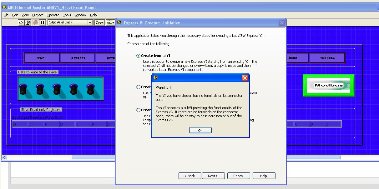
Estoy modificando UN SCADA in the empresa in donde trabajo pero el problema as hay are consta esta para trabajar con FIELDPOINTS, yo eliminate los fieldpoints u OPC powered through y con PLC of MODBUS TCPIP similarly o serial ABB. Comunicación is the prevalence, puedo leer y señales analogicas write y digitales pero el escollo librar trato're como VI individual intensification has the perfeccion, pero ago al of integrarlo hora of SCADA no works, me errores marca el as como modulo escritura y lectura modbus esta receiving characters no aceptados o things asi extranas, estos momentos estoy tratando crear a Subvi don't express pero no is como hacerlo , is that the of primero doy a tools y ahi in crear una nueva express vi, of doy NEW despues en CREATE from a VI selecciono mi VI y me appears lo siguiente:
SE me hace porque mi vi tiene tickets extraño y salidas, in this case tickets las salidas St o o reels pero no be that pasa.
También estoy intentando hacer algo con las share if is you can hacer algo pero tampoco, en so mi problema're than mi SCADA y MODBUS corran al mismo tiempo, tambien initiates include todo el vi in SCADA el plano y cuando llega el programa ahi flow to para todo, ahi is is, variables, supuse than era una structure while , is the altogether there are quick-witted pero solo is me da UN valor.
Ojala me can help alguien esto is to give has a client unos dias UN y todo esta por eso paradox.
Mucho thank knew tiempo, reciban a cordial saludo.
ING. A. Abraham. Alfonseca Melendez
Normal
0fake
fake
fakeEN-US
X NONE
X NONEMicrosoftInternetExplorer4
/ * Style definitions * /.
table. MsoNormalTable
{mso-style-name: "Table Normal";}
MSO-knew-rowband-size: 0;
MSO-knew-colband-size: 0;
MSO-style - noshow:yes;
MSO-style-priority: 99;
MSO-style - qformat:yes;
"mso-style-parent:" ";" "
MSO-padding-alt: 0 to 5.4pt 0 to 5.4pt;
MSO-para-margin-top: 0;
MSO-para-margin-right: 0;
MSO-para-margin-bottom: 10.0pt;
MSO-para-margin-left: 0;
line-height: 115%;
MSO-pagination: widow-orphan;
font-size: 11.0pt;
font family: 'Calibri', 'sans-serif ';
MSO-ascii-font-family: Calibri;
MSO-ascii-theme-make: minor-latin;
mso-fareast-font-family: "Times New Roman";
mso-fareast-theme-make: minor-fareast.
MSO-hansi-font-family: Calibri;
MSO-hansi-theme-make: minor-latin ;}Hola Abraham, the advantage of
comunicarte con directly los lugar por MODBUS FielPoints are that the communication
haces el through pilot directly variables compartidas, ahora o
con estos tambien you puedes Comunicar por MODBUS. Para con MODBUS communication
Server i/o MODBUS to estas using el este esta LabVIEW RT o en LabVIEW DSC, o
the MODBUS libreria utilizando estas. ?Ahora el error that you
Genera el del VI Express are you porque VI not las tiene nada en contacts
Terminal, an esto is refiere don't con as no tickets tiene y salidas. Ahora
probably aqui no using screw Express, the utility of los need live
Express General are building as despues con use en herramientas para
Los programas mas than fr if a component in a specific en programa, y proven
MAS well utility para el Worflow para el programa final.Ahora el problema aqui of
No funcionen juntos can be much more than a problem of integration. Como so
mencionas you colocas a Subvi, con a ciclo while inside of a VI, VI el
main goes a detenido meet (o por lo menos el ciclo in el as metiste
Este Subvi) terminen run one until. Quitar el ciclo Al solo everything is
runs una vez cada vez lo controls has call desde el principal, so solo lo
Mandas call una vez solo you will a dar UN dato.Ahora lo mas algo
con el to use are simple as puedes hacer I/O Server in case of than cuentes
El, there is what sets el I/O server variable ligar puedes compartidas has los
looking for MODBUS, y como utilizarlos compartidas variables in you sistema
SCADA.Estas ligas you pueden ser
utility of:Connected LabVIEW has any red Industrial y PLC.
Developer Zone - National InstrumentsHow to turn an RT target in Modbus slave using i/o
Servers - Developer Zone - National InstrumentsConnected LabVIEW has any red Industrial y PLC.
Developer Zone - National InstrumentsSaludos
-
Isolated ground and analog ground in Multisim
What is the availability of isolated or analog grounds in Multisim? Multisim allows 2 main types of designs, standard ground (can also be called grounding, represented always net '0') and digital terrestrial, but sometimes in a design, you will need several references to the ground for the different areas of design, including a ground Earth or chassis point, digital and analog ground terrestrial and sometimes ground isolated.
How that this can be accommodated in a modeling Multisim and the point of view of layout?
Kind regards
Patrick Noonan
Business Development Manager
National Instruments - Electronics Workbench Group
50 market St 1-
South Portland, ME 04106
Phone: 207 892-9130
E-mail: [email protected]Here are examples:
Other reasons Example.ms10 - example of Multisim illustrating how to connect and measure, CGDN, IGND and V_ISO and ALWAYS
Isolated from Source and Earth Example.ms10 - another example showing IGND and V_ISO measured relative to the Earth (0 net)
Special_Gnds.Prz - update database file - creates the new family of "Special_GNDs" (Multisim 10.1)
Thanks to the original user who have requested them.
Kind regards
Patrick Noonan
Business Development Manager
National Instruments - Electronics Workbench Group
50 market St 1-
South Portland, ME 04106
Phone: 207 892-9130
E-mail: [email protected] -
Waveshaping circuit using a 555 timer
I tried to reproduce this circuit much longer. I am trying to use a timer 555 as an Astable multivibrator with a suddenly IC monostable circuit. However, when I create the circuit and use different combinations of RC I actually get a correct output of the timer, but it does not cause the one-shot get active then and I can immediately connect a clock of multisim that turned the circuit works very well. Can someone please take a look on the circuit, I have designed and see where I was wrong? Refer to the multisim file attached.
Sorry for the delay on this point - we have been busy in the ISF group.
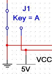
Your tour was very close! I think that by not only not the CLR and a cable entries, your circuit had problems. Probably the pins of the CLR was defaulting to a low logic (requiring so low Q and Q ~ high) as indicated in the data sheet.
Here is the circuit has been corrected (note I increased the capacitor to give lasting impulse on Q / Q ~ because the pulse of the 555 timer period was approximately 250 ms).
In dealing with digital circuits, it is often convenient connect digital inputs to an interactive SPDT switch and VCC (or any level of CMOS circuit is in) and ground as I did here. This gives you the ability to interactively control parts of the interactive test circuit...
Kind regards
Patrick Noonan
Business Development Manager
National Instruments - Electronics Workbench Group -
Hello members of the jury.
First of all, I am very new to multisim and this Council.
I tried to search the kittmaster database and this forum with some luck.
What I'm looking for is a component file of LM35 can I use in multisim. (if there is, a diode or with a voltage coefficient of + 10mV / * C.)
Thank you.
Toebs ,
This link: http://www.cjseymour.plus.com/elec/tempsens/tempsens.htm, has a model the LM35 SPICE. You can perform an analysis of temperature scanning or you can set the simulation of operating temp in the interactive simulation of setting Scan Options (the default is 27degC).
To set something different, go to the menu, simulate-> Simulation Interactive settings-> Analysis Options (tab) and click the button "Customize".
Here locate the SPICE analysis arrangement, "Operating Temperature, TEMP", check the box and change the default value to override the default value.
Test circuit see below LM35
Kind regards
Patrick Noonan
Business Development Manager
National Instruments - Electronics Workbench Group
50 street market 1A
S. Portland, ME 04106
E-mail: [email protected]
Phone: (207) 892-9130
Telec. (207) 892-9508 -
Hola experts experts
Quiero saber como the hago para comprimir voz in labview y enviar por el protocolo tcp - ip internet through poderla gracias
Hola Bernardo, para comprimir los datos ordered usar lagunas functions of the box tools of aforementioned señales advanced (este trae estos examples) LabVIEW Advanced Signal Processing Toolkit Shipping examples - Developer Zone - National Instruments)
Otra opcion are used United Nations data for example para compresion DLL to convert WAV a MP3 y enviar los datos that genres are of you.
También esta libreria test ordered:
http://sine.NI.com/DevZone/CDA/EPD/p/ID/3662
Inncultura
-
What labview 7.1 compatible with windows 7
Now I'm using labview 7.1 under windows XP. I intend to buy a new laptop (Dell Inspiron preference), and I got to know only the very latest editions come with Windows 7. Also, it not is not possible to make windows XP operating system for laptop above that the drivers are not available and many features would not work. I'm not able to buy the latest version of Labview also. There is a compatibility problem between Windows 7 and Labview 7.1
LabVIEW 2009 and November 2009 device drivers DVD NOT officially support Windows 7. Official support indicates that we have tested the products and that bugs will be processed by our normal support process, which is documented in the software engineering process for the development of National Instruments products.
National products Instruments released before the above versions are not officially supported on Windows 7. However, Microsoft said that most of the applications supported on Windows Vista will run smoothly on Windows 7 because of the underlying similarity of two operating systems as described in How compatible are your applications? Therefore, you can install and use these products on Windows 7 without problem.
-
1. is there a way to rotate the net names and/or names of bus to follow the thread if it slides vertically? The shift/R command does not work. (Version 10.1 Power Pro).
2. names may be off grid? There is no reason to snap a name to the grid. There are times when the name is crowded, or on an adjacent line. It seems very little professional and sloppy.
Thanks for the help,
Scotty544
Scotty544,
1 there is no support for rotated text (vertical) currently in v10.1. The only support existing within components where you can rotate the name of pin (horiz/green), but this won't help you with the names of wiring.
2. I agree with what you say with the net name labels - they don't behave well when rewire you / move threads. You can lock, but if you move the wire or rewiring that they don't change very much at all. For simulation work, I generally recommend leaving the net names enabled, however if you are planning to print your diagram for PCB layout purposes or documentation, you can universally turn labels (options-> properties sheet-> Circuit [tab]-> name [region]) and set it to 'Hide All' or 'using the specific setting Net '. Note the use of the net specific parameter will force through the diagram, then choose threads are visible.
Another thread of labelling approach...
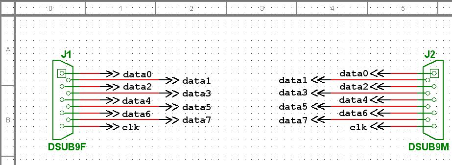
In general, I recommend the use of text (Ctrl + T) or observation points (location-> comment) to specific key within the circuit for documentation purposes. Also, for the connections that need to go elsewhere (such an escape of connector), you can use the functionality of virtual wiring (netnames need all display or use Net specific setting) or you can use the external page (Place->-> stop Page Plug connectors) connector... Page connector is typically used to connect to, of course, the connections off-page... If you place a link second off-page down and try to adjust the "RefDes" parameter to match the first manually - double-clicking a message will appear saying "all components must have unique benchmark indicators" and the action will be prevented... however it is a little trick that can be used to connect to the connectors on the same page. When you place the second connector off-page down, go to the spreadsheet view and select the components tab. On the first column named "Refdes" go down on the second connector that you want to copy the name to the net and just rename it to match the first. Multisim will warn you when connect you 2 NET names together on the same page (but that's the idea)... so you can now have net "data0" connected to "data0' with a connector off specific page elsewhere in your design both external and within the page to other pages. Also, you will have better control the alignment of text - and the label will move with the connector much better with straight wire labels...
Also note that in general, we work to improve the wiring and the net labeling behavior.
Kind regards
Patrick Noonan
Business Development Manager
National Instruments - Electronics Workbench Group
50 market St 1-
South Portland, ME 04106
Phone: 207 892-9130
E-mail: [email protected] -
Hello
is there an element of 485 communication, both single direction and communication in two ways. or where I can find this model
problem of the anther, in multisim library, having a component of communication infrad Red?
Thank you!
We have an existing discussion on RS - 485, but the SPICE model evolves from an IBIS model. What this means is that, generally, IBIS is good to show you the transition to digital and data loading, but not likely you will get a functional model of SPICES you want. Here are the previous thread.
http://forums.NI.com/NI/board/message?board.ID=370&thread.id=844
RS485 transceivers are relatively simple, but they convert ended to differential signals and speed and the specifications that could create a functional model of charging base. As a starting point, you NOTICE specific in mind, there are several Maxim (full/half duplex) which could be appropriate choices?
Same question with the infrared communication component - please let us know a reference number of a typical device would seek you to.
Kind regards
Patrick Noonan
Business Development Manager
National Instruments - Electronics Workbench Group
50 street market 1A
S. Portland, ME 04106
E-mail: [email protected]
Phone: (207) 892-9130
Telec. (512) 683-7754 -
Ultiboard gel when moving components
Hello
As I solved it my previous problem, I came across another.
In Ultiboard, when I try to move some components (such as a driver or FET) my Ultiboard program just freeze.
I can't change it's shape or whatever, but it does not solve my problem. It still freezes my Ultiboard when he moves.
I noticed that the problem is in my drawing itself. I tried to move the items on 3 different computers, with all the same result.
It's really taking me a lot of time, actually too; as I'm getting really close to my limit.
I really hope someone can help out me.
Thanks in advance.
Erik
Try this and let us know what happened...
First disable complete control real-time DRC... in the Options-> global preferences menu and in the "PCB Design" tab, select the option 'no real time control' under the net of DRC & check settings. Try to move the part, does that help?
Disable the second part hustle... the menu Options-> part push and click the icon to toggle the mode. Try to move the part, does that help?
Let us know if any of these actions solve or improve the situation. Is it not possible to present your design (file .ewprj) via our support link to one of our Application Engineers can diagnose the situation?
Go to http://sine.ni.com/apps/utf8/niae_asc.main to start a session of e-mail support.
Kind regards
Patrick Noonan
Business Development Manager
National Instruments - Electronics Workbench Group
50 street market 1A
S. Portland, ME 04106
E-mail: [email protected]
Phone: (207) 892-9130
Telec. (207) 892-9508 -
Coaxial connector in Multisim component
Hello
Im looking for a component of coaxial connector in the Multisim database as well as the site of components listed here. But I couldn't find one. Can someone get me a clue on how to find it. Thank you.
hers,
There are several symbols of 2-pin connector that you could use and attach them to the available Ultiboard fingerprints or footprints BNC customized based on what it takes, however, here is a diagram with a BNC connector for example with a standard configuration of symbol of the BNC.
Do not hesitate to register for databases, and customize with no specific information (that was created for a 50 ohm coax).
Kind regards
Patrick Noonan
Business Development Manager
National Instruments - Electronics Workbench Group
50 street market 1A
S. Portland, ME 04106
E-mail: [email protected]
Phone: (207) 892-9130
Telec. (207) 892-9508 -
A program caused the blocking of the program works correctly
Hello
I developed using National Instruments LabWindows/CVI software and installed the .exe in a PC running Windows 7 32 bit with 4 GB of RAM.
When I run my software, sometimes I get the following error.
"A program caused blocking the program works correctly. Windows will close the program and notify you if a solution is available.
It's very random, and sometimes this error never happens.
Can someone help me understand this issue please. I saw my software code several times and I am sure that I do nothing wrong in the software that causes this error coming.
Is this all related to windows and how can I solve this problem? Help is very appreciated.
Thank you
Sujith Fox
Sujith,
Given that you have developed this program, you should know better, but try to check for error events in Event Viewer
You can also publish in MSDN for assistance
-
How can I determine which instruments have been developed by Microsoft
I went on the link below and they show a number of gadgets, but then they warn that other than those developed by Microsoft gadgets may collect information about you on your computer activity. Therefore, I would like to know what instruments have been developed by Microsoft.
http://Windows.Microsoft.com/en-CA/Windows/downloads/personalize/gadgets
It gives the name of the developer under each gadget on the page you mention. Gadgets on this page the only listed as being developed by Microsoft's MSN Headlines (32 bit).
-
Y at - it a USB Instrument for CVI driver development tool
Is there a USB driver tool developer tool/guide for CVI?
Thank you
Chip b.
Stuff here:
http://zone.NI.com/DevZone/CDA/tut/p/ID/4478
So much to USB... so little time...

Maybe you are looking for
-
a Web site asks me to install something, I'm not sure that it is legitimate
Hi, all. on a tourist site, I clicked on the link for a list of shopping places. I get a notice that says: "you must install this thing to get this link to work." It has a logo of firefox, but I'm still nervous, having obtained Burns very badly once
-
When I open a new tab, it always comes to the top: http://ISearch.AVG.com/Tab?CID= {7d7746b8-fb39-4619-86fd-792cbc268005} & mid = 72dc207d310ff3c58bd4dbeaeddede3a-fe6a71ecae4eb764a90a5203c991f01a6245f52e & ds = AVG & v = 13.2.0.5 & lang = es - & pr =
-
Pavilion 15-E065SB replacing the screen
Hello I cracked the screen of my flag 15, recently and I can't really afford to pay the repaircost HP could charge me to fix it, so I want to do it myself (I have experience with Assembly material). I do not know what replacement screen I need to ord
-
Number of words in document displayed in Windows Explorer does not.
When I had Vista, I really liked the fact that Windows Explorer displays the number of words in a Word document using the «Détails» Until I realized that, without apparent reason, it displays the number of words sometimes change to one that is totall
-
Hotmail says impossible to disconnect
Help... I CAN'T DISCONNECT MY HOTMAIL