DeviceNet explicit an Ion gaige in Labview 6i e-mail
Hello
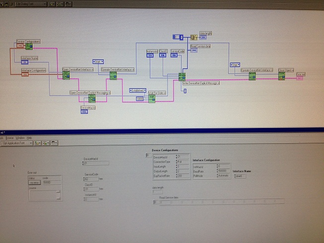
I am trying to send an explicit message to an ION gauge via Labview 6i. I have the gauge works on the network and can read the pressure via an another update Vi, but when it comes to writing of orders via the method explicit message - it's new to me, and worse I get no response from the unit.
It's to make me a lot of things, but having never made before, so don't not sure what.
Can somone take a look at the code and tell me what I'm doing wrong?
Basically sending a message Service Code 62, ClassID 31, Instance ID 2 explicit everywhere at MACID21 - which should turn on the show (ION gauge element) but it does nothing...
Heeeeelp.
Steve
Hi - Thanks for your help.
Gauges I've had were poorly resolved by the manufacturer, they said bad explicit message orders... so it was never going to work.
I am happy that it seems OK otherwise.
Steve
Tags: NI Software
Similar Questions
-
Support of NOR-DNET for LabVIEW 2013
We currently use OR DNET 1.6.6 with LabVIEW 2011. I installed LabVIEW 2013 now also on my computer and tried to synchronize all of the drivers with my installation of LabVIEW 2011.
Well, it seems that NEITHER-DNET does not support LabVIEW 2013, at least officially. compatibility of Version of LabVIEW and NOR-DNET indicates that NEITHER-DNET 1.6.6 supports 2011 NOR-DNET 1.6.7 2012 LabVIEW and LabVIEW.
The list NOR system driver November 2013 set OR DNET 1.6.7 defined pilot. When I try to install it, there is no support for LabVIEW 2013.
My question is, if there is a plan to include support OR DNET for LabVIEW 2013 or later in the game to pilot?
I copied the directories vi.lib\DeviceNet and vi.lib\nidnet of LabVIEW 2011-2013 and I can load my programs without any problems. I always did not build an executable and does not run on the test set-up, but projects can be loaded in LabVIEW 2013 without any screws of brocken. should I expect any problems running LabVIEW 2013 with the NOR-DNET to 1.6.6 and 1.6.7 driver?
Nick
There should not be problems but it is a former pilot, we will not be updated for the future version of labview.
-
Meet an applescript event in LabView 2009 (Mac OSX) VI
I have a LabView VI that works constantly, acquisition of data at a remote location. I recently bought a UPS for power cuts, and I would like to be notified by LabView by e-mail that an event has occurred. Can I have the UPS software run an executable when there is a power failure, so my question is this:
How to run an executable file (preferably AppleScript) and have it trigger an event in LabView 2009?
The main VI is still running, and I would like to respond to an event and send a mail/text to the appropriate personnel, so that they can respond accordingly to the power failure. In addition, if power failure, I can then stop the experience "smoothly."
It seems that all the pieces have to exist to do this, but I can't find a way to get there. Thank you in advance, this will make many people happy!
News: Mac OS X 10.5.8, LabView 2009
Hi jumpman Jr,.
When you say that the UPS software may run an executable file, which means that it can run an executable of LabVIEW? If so, you can write a small executable of LabVIEW to send an email to a specified address. In the measurement of the notifying the main VI that is running, you can try to communicate between the executable and the VI using the methods of normal communication of VI at VI, i.e. global variables, functional global variables, shared variable network published, or even tax filers or queues. Then you can safely leave your main VI.
Aaron P
National Instruments
Technical sales engineer
-
Using PCI-8532 with NOR-DNET 1.6.6 / NOR-DNET 2.0.2
I have a PC with the following configuration test set-up:
- Card PCI-8532 DeviceNet
- Windows 7 Enterprise, SP 1
- LabVIEW 2010 Runtime
- NOR-DNET 1.6.6 with MAX 5.0
- No environment of LabVIEW Development
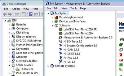
- PCI-8532 isn't available in MAX and Windows Device Manager indicates the card as "PCI Device" with an exclamation mark.
Here is a screenshot of Windows and MAX Device Manager:
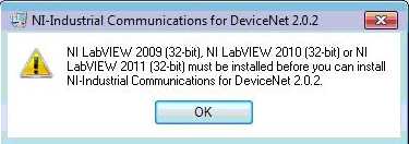
I can't install the NOR-Industrial communications for DeviceNet 2.0.2 on this computer because I get the following error:
Well, I have two questions
- How can I install and use the PCI-8532 and see with NOR-DNET 1.6.6? If this is not possible:
- How can I create an executable file on my system (portable) development with LabVIEW 2010 or 2011 LabVIEW and run this executable on the test set-up. I currently have on my development system:
- Professional 2010 LabVIEW and LabVIEW 2011
- NOR-DNET 1.6.6
- No hardware OR at all
- I have to install the NOR-Industrial Communications for DeviceNet 2.0.2 on my laptop (my development system)
- This will interfere with my current NOR-DNET 1.6.6 and then I select which driver to use at compile time
Thank you
Nick
Nick HY,
No, it is defenitely not a replacement yet and I will work with our Web Department who make clearer on our web page.
The development of the new API is pretty well done, but based on your feedback, we are planning to improve compatibility, so you can for example use the old APi 1.6.x and the new APi of 8532 on the same machine, so you can use the old and the new material on this same machine. Which would be important for you?
For the moment we intend not to allow only one type of material on the same machine to save you development time. Let me know what you think.
To clarify the situation today: The InCOM for Devicenet component is not part of LabVIEW. It's just a very simple means of communication with the I/o variables and blocks of function for the MS. The driver should install fine even without installed LV. The error message is quite a Bug on our side, and the solution would be to use the Builder installer LV to create a new installer that can install 2.0.x Incom Dnet driver without having installed Lv.
And today, you should be able to have the 1.6.x both pilot 2.0.x in parallel and use the API 1.6.x with old boards yonce and the variable approach of IO 2.0.x with your new Board of Directors.
I'll keep this post updated as soon as we have a stable Beta available I'll post something.
DirkW
-
What is the difference between abandonment and reset in Laview FPGA module
Hello
I used Abort in Labview FPGA e-mail trying to stop the running program in FlexRIO while I got an unexpected behavior.
After replacing the demolition of the reset all goes well.
What is the difference between these two functions?
Thank you
Fang
Hello Fang,
If this answers your questions, then please indicate that answers your question by clicking on "accept as a Solution.
If that doesn't answer your questions, so please let me know.
-
Ethernet I / P Communication between Fanuc LR Mate 200iC and LabVIEW
How can I read the outputs and write entries of a device, Ethernet/IP, using the NI Ethernet/IP drivers?
I recently get the NI Ethernet/IP driver OR to communicate with a robot of 200iC Fanuc LR Mate using this communication protocol. In fact, I set up the robot as a parameter to map digital 1 to 64 and output digital from 1 to 64 and through the Ethernet/IP configuration.
What I do is for example, a specific moment in my logic to the status of an output of the Fanuc Robot to take measures, or give some input to the Fanuc Robot so do some operations. Now, as I noted above, I get this drivers recently and apparently they are new or regular technical support do not support for this product. Basically there is no apartment of the LabVIEW help on this driver documentation, and this help doesn't help too much.
So, if someone can help me to make this work I really appreciate it a lot. I'm in the middle of a project we showld integrate via Ethernet/IP. Here is a screenshot of the the inputs and outputs in the configuration of Fanuc Robot are on Slot 1. Attached is a table with a summary of the Fanuc Robot of the configuration settings that should be used to set up the scanner (in this case, LabVIEW):
I'm using LabVIEW 2011 with Ethernet/IP v1.2 drivers on a Windows 7 Professional
Once again, any help on this will be really appreciated. Thank you.
Hi Ferdinand,.
Please refer to the help as documentation below:
1. open LabVIEW, go to the Help Menu-> NOR-Industrial Communications for Ethernet/IP. This is documentation of EIP support for all applications.
2. in him getting started window of LabVIEW, please go to find examples. And check the directory:
Input and output hardware-> NOR-Industrial Communications-> EtherNet/IP
In this directory, there are several examples of use of the PPC.
And for your case, read the example in ".vi AccessAssablyInstanceData (Explicit)", which should be very similar.
For any question below, please do not hesitate to contact me.
Thank you.
Chris
-
Ethernet/IP implicit messaging is possible in labview, PC
Hello
I'm trying to communicate in labview 2011 PC with welder ultrasonic who etherent/ip, for labview real-time data, PC and want to connect data and view graphs
I had installed the EIP toolkit
The welder have
* Message explicit for the configuration of the parameters
I can connect to the welder by explicit messaging, so I had configured settings in welder with EthernetIP ICU get attribute single.vi.
* Implicit message for real-time data, welding
Instance of the entry Assembly: size 101: 12 deformations (48 bytes in total)
Output of the Assembly instance: 102-size: 2 strains (total 8 bytes)
Instance configuration of the Assembly: 103-size: 0 (total 0 bytes)For welding data in real time, I need to communicate but implied message of labview PC.
How to create connectio between labview and welder ultrasound for implicit Messaging.
Hi Emily,.
I'm afraid that you can't create implicit I/O communication between labview and ultrasonic welder.
This is because the driver of the National Instrument is not a scanner, but an adapter (slave) and therefore the position to solder ultrasonic.
This means that we cannot launch an instance of IO. This does not mean the National Instrument driver cannot communicate via e-mail, just that it cannot start this communication.
I know explicit message is not as fast as implicit messaging, but if you are not running transfer limits you can always use explicit messaging.
Explicit messaging speed can reach up to 100 Hz.
Wendy
-
Load a file EDS into LabView 2012
Through research I found that DeviceNet Configurator is no longer available. I'm under LabView 2012 with IndComm/Devicenet 2.2 pilot. What replaces the DeviceNet Configurator? How to load the EDS files?
Thank you
Tennessee Paul
My post here on a different topic, I thought that I would wear it to conclude this thread.
Load an EDS file to the slave device
- Right-click on the slave device
- Select "Sheet"... »
- Click on add files...
- Navigate to the location of the EDS file.
- Select the file.
- Click OK.
- In the left pane, expand the data sheet newly added up to reach the node displays the version.
- Select the version.
- Click OK.
Check the device and file EDS
- Right-click on the slave device
- Select utilities
- Select the Panel of Test online
- Select the option 'Device status' in the field of category on the left.
- On the right, select the slave device, you want to check.
- Click on "check the device".
- Read the errors/warnings or lack thereof.
Edit the file EDS
To change the EDS file, I used EZ-EDS , which is a specific devicenet EDS of ODVA freeware Editor.
I did my corrections and saved my file EDS. (After having saved my original, of course).
Remove the installed Labview EDS file
- Navigate to the following location: C:\ProgramData\National Instruments\NI-IndComm for DeviceNet\Datasheet
- Remove the sheet (Note: there is more that one datasheet added manually.) Additional EDS files come with the IndComm driver. Find the EDS file for the specific device that you want to replace and delete).
-
LabVIEW interface with multiple blocks of Festo module
I am trying to connect with a block of Festo, but I can't. Here are the details:
I'm under Labview 2012 SP1 with IndComm-DeviceNet 2.2 pilot on a 64-bit Windows OS. I installed a PCI 8532 card NOR. I see the map to the MAX.
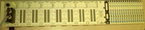
The block of Festo is built with the following Modules: CPX_FB11 (communications module), 4 analog input Modules, 1 Digital module, 2 digital modules followed by 32 Festo valves. (Image below)
Using DeviceNet PXIPCI Basics.lvproj I did the following:
In the project, right-click on desktop > New > targets and devices > existing target or device, discover an existing target or device...
Expand the node of DeviceNet Master Interface, DeviceNet1 chosen and added to the project.
A click on the newly added DeviceNet/device target > New > targets and devices...
Expanded the Festo Block "CPX_FB11" selected DeviceNet slave device and added to the project.
Initially, I received an error card technique 'EDS file no assigned' I solved this by following the direction listed here.
However, I'm unable to "see" anything other than the CPX_FB11 LabView. The tree view of the devices lists not analog, Digital e / s or valves. I can't operate the Valves and IOs digital or analog. When I run the entire project VI they then expire.
Any help would be appreciated.
Thank you
Tennessee Paul
Hi Jesse,.
I'm not entirely sure what the specific problem was. I kept getting strange behavior. Errors in LabView and on my camera from Festo. The EDS files change. So, I did as any natural born THERE would be worker, I rebooted.

Here are the steps I used to get this project going. In doing so, I found that to set up a DeviceNet device in LV2012SP1, no need to manually enter the data in file EDS. There is a tool to load files EDS. It dealt with issues I had in the previous Forum posts: here about loading files EDS in LabView and here regarding setting up a DeviceNet network.
Environment: Windows 7, 64-bit processor. IndComm 2.2 pilot. LabVIEW 2012 SP1
Starting with the example LabView project: "Devicenet PXIPCI Basic.lvproj.
Add a DeviceNet master to a LabView project
- The project: right-click on my computer
- Select new
- Select the targets and the device (s)
- Select the option "discover existing devices.
- Select the discovered device.
- Click 'OK' (Note: in this case, my master is a card PCI of NOR-8532)
Add a DeviceNet slave device to a LabView project
- Right-click on the master device newly added in the project tree
- Select new
- Select the targets and the device (s)
- Select 'discover existing devices.
- Select the discovered device.
- Click OK. (Note: in this case my slave is a block of Festo CPX-FB11.)
Load an EDS file to the slave device
- Right-click on the slave device
- Select "Sheet"... »
- Click on add files...
- Navigate to the location of the EDS file.
- Select the file.
- Click OK.
- In the left pane, expand the data sheet newly added up to reach the node displays the version.
- Select the version.
- Click OK.
Check the device and file EDS
- Right-click on the slave device
- Select utilities
- Select the Panel of Test online
- Select the option 'Device status' in the field of category on the left.
- On the right, select the slave device, you want to check.
- Click on "check the device".
- Read the errors/warnings or lack thereof.
- Navigate to the following location: C:\ProgramData\National Instruments\NI-IndComm for DeviceNet\Datasheet
- Remove the sheet (Note: there is more that one datasheet added manually.) Additional EDS files come with the IndComm driver. Find the EDS file for the specific device that you want to replace and delete).
-
Error when you work with Devicenet in cRIO
Hello
I am trying to use codes for example for industrial Communications using DeviceNET. I have the 9882 OR on a chassis NI 9114 and 9014 controller. I have all the drivers for DeviceNET, RIO, Realtime/FPGA, ect. When I try to run any sample project I get this error:
DeviceNetLIB.lvlib:Wait for State.vi loaded with errors on the target and was closed.
LabVIEW: Unable to load the shared library nidnetapi. *: ncWaitForState:C. to ensure that the library is present on the target of RT. MAX allows you to install software from OR or FTP to transfer custom RT target libraries.Can someone help me to identify the problem and how to solve it.
Thanks in advance.
Jose
DirkW,
My problem was that I used the same address the Interface IN MAC and the device ID. Now I fixed it and it works well.
Thank you
Jose
-
How to find the point of leakage with Labview?
I use a myRIO to develop a system to help people imapaired in their navigation to visually. I already have the image processing of which is to be acquired by the device (edge detection and research of straight lines).
How can I end the vanishing point of the two edges of a path to an image with LabVIEW? There is a special function that I can use?
Thank you!
The vanishing point is the intersection of two lines, no?
-
Interfacing of FTP LabVIEW Sorenson XBT 32-3
I am programmer LabVIEW novice XBT Sorenson 32-3FTP DC Power Supply out of Labview execution attempt, so that I can integrate it as a sub VI into my current program. My control requirements are minimal, I only need to do two things; Turn the power on (or begin just to the power of the source, or the other option is acceptable) and adjust the voltage level at the appropriate level, button or text entry. My questions are twofold;
- Web site OR claims that all drivers on the website of Sorenson are compatible with a GPIB connector, but never mention the possibility of using a USB connector. Mr. Sorenson thinks or the other of these two drivers would work, as well as an RS-232 cable. I just wanted to make sure it's true, because I'm in trouble if only GPIB is taken care.
- If the work of wiring USB so that a GPIB connector, so I wonder if there is anything out there that could achieve both in the database, or even just a suggestion or two of how to manipulate the Sorenson Sub VI of to perform this task.
It doesn't seem like it should be difficult, but when I opened the pre-built drivers for supply, total confusion intervened.
The power supply is:
http://sine.NI.com/apps/UTF8/niid_web_display.model_page?p_model_id=15920
The Power Supply Site is here:
http://www.Sorensen.com/products/XBT/XBT_Downloads.htm
This power comes standard with a USB connection and a RS-232 (serial) connection. The GPIB connection is optional, and unless you bought it, you won't have it. The drivers themselves are written using VISA. VISA supports talking to the instruments or via RS-232, GPIB, TCP/IP (ethernet) or USB. You specify the type of connection via the name of resource VISA. If you open a pilot on the screws, you will see the name of resource VISA control. If you click on the drop down arrow for that, you will get a list of the recognized instruments. This is MAX (Measurement and Automation Explorer).
For USB the instrument must support the Protocol USBTMC. The datasheet for food involves USBTMC, but is not explicit.
For RS - 232 all you will see are the COM ports on your computer.
So, if you have a standard diet, you can simply connect a cable RS-232 for her and the driver can be used. You need to configure the parameters of the serial port with the VI initialize. If you want to try the USB drive, you should check with Sorensen that he does not support the Protocol USBTMC. If Yes, you can install the USB driver and it should appear in MAX (and therefore resources VISA control).
-
Communication problem between LabView and acquisition of data USB 6259
I want to monitor a data USB-6259 acquisition using LabVIEW 8.6. However, when you try to create an explicit task (using the DAQ assistant) in order to acquire a signal, I get the message asked supported device found¨. I can see the USB-6259 under ¨Devices and interfaces¨ to the MAX, but when I try to import the configuration data for NOR-DAQmx 8.7.2 in MAX, I get the message ¨Can´t import file configData.nce. File not found¨. I use NEITHER-DAQmx 8.7.2. Any suggestions?
Corneliu
Hi, Corneliu,
This question could be generated due to a corruption of database of MAX. Here is a link to restore the database to the MAX.
http://digital.NI.com/public.nsf/allkb/2C7480E856987FFF862573AE005AB0D9?OpenDocument
Just follow the steps and let me know if that solves the problem.
A greeting.
Jesus.
-
I am trying to compile an OUTPUT for my Simulink model file by using "nidll_vxworks" and execute it using the Simulation Interface Toolkit for a cRIO 9073. I am able to compile the DLL file by using "nidll" and managed to run the simulation using my PC as a host.
I have already downloaded the files "gccdist" and "vxworks61gccdist" and copied in "c:" when I build the model in Sumulink I get the following error at the end of the process (at the same time windows tells me that "sh.exe" has stopped working). If it's important, I'm on Windows 7 64-bit, but using Matlab 2009 b 32bits and LabView 2010 32-bit. ANY HELP WILL BE APPRECIATED. "QofV" is the name of my Simulink model and I changed to parts of "XXX" in the path of the file.
6.1 CCG is only supported on Windows XP. It is almost indicated in the readme_sit_vxworks.txt found in C:\SimulationInterfaceToolkit\xxxx\VxWorks (where xxxx is the version of the DIS). It is said:
* Known issues

---------------------------

-WindRiver GNU Toolchain 6.3 and 6.1 do not work on Windows Vista.
To be more explicit, it should be "Vista and later.
Carl L
National Instruments
-
Drivers Xilinx/Multisim and Labview FPGA
Where can I find drivers for my FPGA OR if I use Multisim/Xilinx and NOT of Labview? All the links I found are Labview be installed. However, the explicit manual FPGA indicates that you can use Multisim/XIlinx ISE in place.
OK, I tested just outside. The Driver of LabVIEW 2013 DEFB contains 2 separate components, the driver and Module FPGA support. If you run this installer, it won't check if you have LabVIEW FPGA installed unless you check the box for LabVIEW FPGA support.
I can change the text in the Installation Instructions to read "LabVIEW FPGA 2013 is required to install the LabVIEW FPGA Module Support component installation".
In my case I had errors in my EDS file. Basically the slave device was not defined for the correct number of bytes of input/output in the EDS, i.e. a wrong configuration file. To fix this I had to change the EDS file.
Edit the file EDS
To change the EDS file, I used EZ-EDS , which is a freeware, devicenet specific EDS editor of ODVA.
I did my corrections and saved my file EDS. (After having saved my original, of course).
Remove the installed Labview EDS file
I restarted LabView.
I went through the steps above again and loaded my new EDS file.
I saved the project and came out of LabView.
I rebooted the computer and the slave device.
I restarted the project and launched a VI.
I was able to communicate with the device. That is something that I had not been able to do before. And, in doing so, I discovered how the device speak and why were not each module. (I have a standard for my block devices EDS file, as it appears that LabVIEW is not capable of a modular system that requires an EDS file for each module. I could be wrong on that last part though, as there may be a setting on my real device. But it is unecssary in my project. So I do not consider this further.) Because I was using a standard file of the EDS, only a single slave device showed, and so the data for each module are in the stream of bytes returned to the DeviceNet network. Addressing each module is a question of analysis the bits and the bytes appropriate.
Thank you
Tennessee Paul
Maybe you are looking for
-
Mac and Action Delete mail rules
I use Mail 9.3 with El Capitan 10.11.6 and by mistake, I created an automatic e-mail rule that removed all email in my Inbox. This was due to accidentally clicking on the "If the following RULES are respected", instead of ALL. I got the error after a
-
I had carbonite backup but now have no income and then how can I back up to my new HP and my old XP (?) Office and it will save all that carbonite did? Please write to me atEmail removed for privacy
-
my screen flipped upside down how can I sort it please
my screen flipped upside down how can I sort it please
-
Windows 7 and WMPlayer don't is not loading
WMPlayer worked very well and I have probably 100 playlists of music, then I bought some iTune songs (what I had done before without any problem) and now when I click on WMP, it appears "Welcome to Windows Media Player" screen where I am suppose to s
-
Any java API to delete an e-mail account
At the present time, I have implemented the code to remove emails from a particular e-mail account and I also implemented listener to record to the deletion of all new emails coming. I am also looking for some API to remove him leads of the device e-