Differential temperature controller
Hi all
I just want to start by saying that I am completely new to labVIEW has so forgive my ignorance if my questions seem unnecessary.
I'm trying to figure out how to get my differential temperature controller to work on labVIEW.
Currently using the cRIO and NI 9472 c series module that sends Boolean signals to a relay.
I am able 2 temperatures A and B. What I'm trying to achieve:
If A - B > 8 degrees TRUE signs. As soon as A - B< 4="" degrees="" send="" false="">
Seems simple, but the problem I have is when A - B rises above 4 again, it sends a REAL signal, which is what I don't want.
I need the signal to remain FALSE until is exceeds 8 degrees, then run it again. There is a sample application for differential controller, but I found that it was outdated for the software, I'm using and also too complicated to decipher what is happening.
I just want to send ON / OFF commands (TRUE/FALSE).
Any help will be really appreciated,
William
Hi all
Problem solved - I went through each State individually and it broke down into elements simple that I can understand and then found the best solution for each State.
All he needed was a brain power - moral of the story don't let not the computer thinks for himself.
Thanks for the help.
William
Tags: NI Hardware
Similar Questions
-
Satellite M70-131 Linux temperature controller
Hi all.
I just got my hands on a satellite m70-131 and I am having trouble with Linux temperature controller.
Anyone know what sensors it runs? The SMBus is detected but just lm_sensors detects any sensors.
Any ideas?
Thank you all!Hello
Sorry, it failed for me to find all the details about this sensor, but I found this useful page on the monitoring of applications for Linux of temperature:
http://Linux.Softpedia.com/get/system/monitoring/laptop-temperature-monitor-4445.shtml -
Lakeshore temperature controller
Hello Forum,
I downloaded the drivers for Lakeshore 331 temperature controller and I'm trying to implement, without success. (I'm a time-out error to my VISA playback function). So, I used my base series write and Read.vi to check if the cables and ports are working properly by simply writing to the controller ' * IDN? \r\n "." Rather than retrieve the expected "LSCI, MODEL 332 S, 332603, 112002', I get the answer garbeled indicated in the attached file." The message read contains exactly the right number of bits, so I know that my computer is able to communicate with the controller. But why can we not responded in intelligible language? Is this due to a mistake in my computer settings or labview or with the controller? In addition, this is why I can't use the driver.
Any help would be greatly appreciated,
L
This happens usually when your serial port settings and those on the device do not match. Make sure you use the same settings (baud rate, stop bits, parity, flow etc.) on both sides of the connection.
-
question on temperature controller
Hey guys!
I'm unable to collect data from a temperature controller using its own driver. The model of the instrument is ILX Lightwave LDT - 5910-B. The problem is that I want to raise the temperature in a very small step, for example 0.01 C deg / step or even 0.005 deg C/step. I want to put the step by a logic using labview, because I can't find any setting from the temperature controller manual. Anyone have any suggestions for how to do this?
Thank you!
Hai,
First to justify if the controller has the ability to control the temperature up to this resolution (0.001deg C). I got a glance of this collection of models and he 0.2deg C.
It has an interface GPIB through which you can set the required parameters. For GPIB communication, you can use the PCI-GPIB or GPIB-USB interfaces to control the instrument.
For the basics on instrument control GPIB see here:http://zone.ni.com/devzone/cda/tut/p/id/2761
-
Temperature controller gives wrong powerup configuration after communicating with RS-232
Hello
I was working with a temperature controller Programmable of Lakeshore 330 using the LabVIEW drivers downloaded from the pilot site OR. My goal was to implement a continuous of RS232 data acquisition. I initially thought of using code similar to that used in another sensor (a pressure sensor that acquires data from RS232 continuously). Unfortunately, I kept this vi in the vi even because the I am developing. When executing the vi, I got error by the pressure transducer, which is possible because the two transducers are trying to communicate by using the same serial port. After this, my temperature Lakeshore 330 controller always turn on in a bad configuration. I can't change the input string. Also, in temperature measurement, the two numbers after that the comma is missing. For example, instead of 21.43 is just showing 21.
Anyone know what's happened here? I restarted the Lakeshore several times, always without change. Is it possible that the command of erroneous entry on the Lake spoiled the setting somehow? It is possible to return to the original factory puts. I'm getting desperate.
I appreciate deeply all help and suggestions.
Thanks in advance
Zch
It is really not a problem of LabVIEW, but a user error.
All I can say is that you read the manual for the controller of Lakeshore. They are either going to have a few steps that you can use to reconfigure using the controls in the Panel before, or perhaps their own software to help set it up. Also look at regardless of the Protocol that they use for serial communication. Compare that to what you were trying to do with peripheral pressure can tell you how you may have accidentally changed the configuration of controllers mixed Lakeshore when you got their code and serial ports.
-
Reading the words of temperature controller fits using Modbus
I'm working on a project that involves the use of a certain number of temperature controllers, Omega CN 7823 s. The Protocol of communication for them is RS485 Modbus ASCII or RTU.
I had a bit of trouble getting a job of communicating. I think I do everything correctly in terms of setting up the initial communication parameters (baud rate, parity, etc.), but have been unable to properly read the values. I am able to write values to operating records, but cannot read them. When I try to read (using the code 03), the result is simply a multiple of 256 (if I try to read registry 1001 H, which is 4097 in decimal form, I get a result of 256).
I'm running in ASCII at a speed of 9600, 7-bit data length, parity and 1 stop bit.
Any help would be appreciated - I am attaching my VI and the manual of the controller.
In the end it turned out that I had to create a property node to the VISA Instrument and specify the mode series RS-485/2-Auto. This allowed the computer read the response from the controllers of temperature instead of simply reading the message that was sent to them. I wish I had discovered this day 1, 2 or 3 to work on this problem, instead of the day 5.
-
Excel sheet entry to 'setpoint' of the PID controller
Hello
I use this (attached) vi to control the thermostat of Lakeshore. I got the website vi OR. I want to change the vi as to the set value, it takes as input an excel sheet (could be any other form too). This spreadsheet contains a list of temperatures. The vi reads the first temperature and then that sets the value of the PID controller setpoint. Once the set point is 'set' the vi waiting for awhile (say 1 hour) before reading the next entry in the excel sheet set point. I want to wait that it is because I programmed a gamma spectrum software such that it counts for 1 hour and then starts a new count. The part of the spectrum is not very intelligent but its ok for now. The problem I have is that when I run this vi (attached), the indication of the set on the temperature controller (hardware) tends to zero and stays there. Can someone help me by pointing out the error that I do. This vi is Labview based 6.0 (it's a bad implementation!)
Thank you
Saurabh
Slim,
You could possibly have the calendar in step in the worksheet as well?
It would be a classic case where you could use state machines (or producer / consumer - events if the user input is critical), research of this architecture and examples on ni.com. Also for synchronization purposes, are looking for functional global timer or try to modify this example https://decibel.ni.com/content/docs/DOC-6523 to add 'elapsed time' (as in the elapsed time express vi) features similar to this code.
You have reports such as:
Initialization: initialize your control panel front/graphics etc. Read the spreadsheet file. Make sure that the comms exist between the software and the controller, etc..
Set the temperature: set the first value, start a countdown (depending on what you set)
State check: check the status of controller etc failure. Check if the user has pressed the stop button. Check if the timer in the previous state has expired?
In case of error stop the timer and take the measures necessary to correct, to report to the user
If the user has pressed the stop button, close all references, etc hard reset and exit the application.
If the timer has expired, get the next value and go on to set the temperature.
I hope this helps.
-
The temperature of the SensaTronics in HQ?
I'm putting in place a Sensatronics temperature controller at HQ, but did not get very far. I don't know how to get the controlled temperature sensors.
Can anyone help?
Kind regards
Tonni.Mirko, I can't thank you enough for you efforts
You're a brilliant man.
-Original Message-
From: [email protected] [mailto:[email protected]]
On behalf of Mirko Pluhar
Sent: 27 September 2007 08:38
To: [email protected]
Subject: Re: monitor of Sensatronics temperature in HQ?Hi Paul,.
got a trial version of an installed SNMP Simulator and got identical
effects.
Give me some time to reissue the pluginSee you soon
Mirko______________________________________________________________________
PRIVACY NOTICE
The information contained in this email is confidential and are intended solely for the addressee. Access to this email by anyone else is unauthorized. If you are not the intended recipient, you must not read, use, or disseminate information. The views expressed in this message are those of the individual sender, except where the sender specifically says that they are the views of the Net a Porter Ltd.NET A Porter Ltd is a company registered in England country of Wales & number: 3820604 registered office: The Dome, 151 Queensway, Whiteleys Centre, London W2 4YN.
_____________________________________________________________________ -
My PowerMac G5 hangs on me... starts to show the horizontal lines and graphics have been "bleeding" that is, when you move a title bar, it will leave a trace... now it crashes intermittently? any help?
Hello
Have you blown dust lately?
Get the temperature controller to see if it is heat related...
-
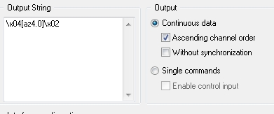
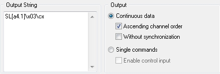
RS232 output Module - checksum on the part of string
I am short of DASYLab 11 and try to write a set value of a Eurotherm temperature controller via the AE-BISYNCHRONES on RS232 Protocol. To do this, I have send some control characters as well as the address of the unit I'm dominant, then the a few characters command and the new set point, then a checksum XOR of the second part of the string (control characters + new set point). I can't find a way to do it, as the format /cx command gives the checksum of the entire string. I tried to place the first part of the string in the channel, the second part and the trainer of checksum in channel two, and then click sequential output, but that has not worked. Someone at - it any other ideas?
Thanks for your time!
What happens if you do it this way?
RS232 output configuration with 2 channels.
Channel 0 is... the entrance is from a module variable overall reading that has the unit number (11).
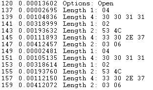
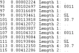
Channel 1 is this--it would come a slider or other inputs.
When I look at my serial port monitor, I get this... hex on the left, to the right ascii...
-
All my instruments back VISA errors
I recently added the cryogenic temperature controller pilot Lake Shore model 336 in the folder instr.lib under program files of National Instruments. When I tried to run one of the example programs accompanying the driver, LabView gave:
1073807346 error occurred while VISA opening to edge the Lake 336.lvlib:Initialize.vi-> Lake Shore 336 write Curve.vi
Because I was working on an another VI at the time I just ignored the error and planned to fix it later. The other program, which had a servo error since last week-free motor, are also starting to give an error:
Error 1073807343 has occurred to clear VISA
Improper installation of the Lake Shore drivers affect somehow my other instruments? I am running LabView 2012 and have NI-VISA 4.6.
Thanks for any help.
Lakeshore pilots apply their own version of VISA? Sometimes conflicting versions of VISA can cause problems.
Lynn
-
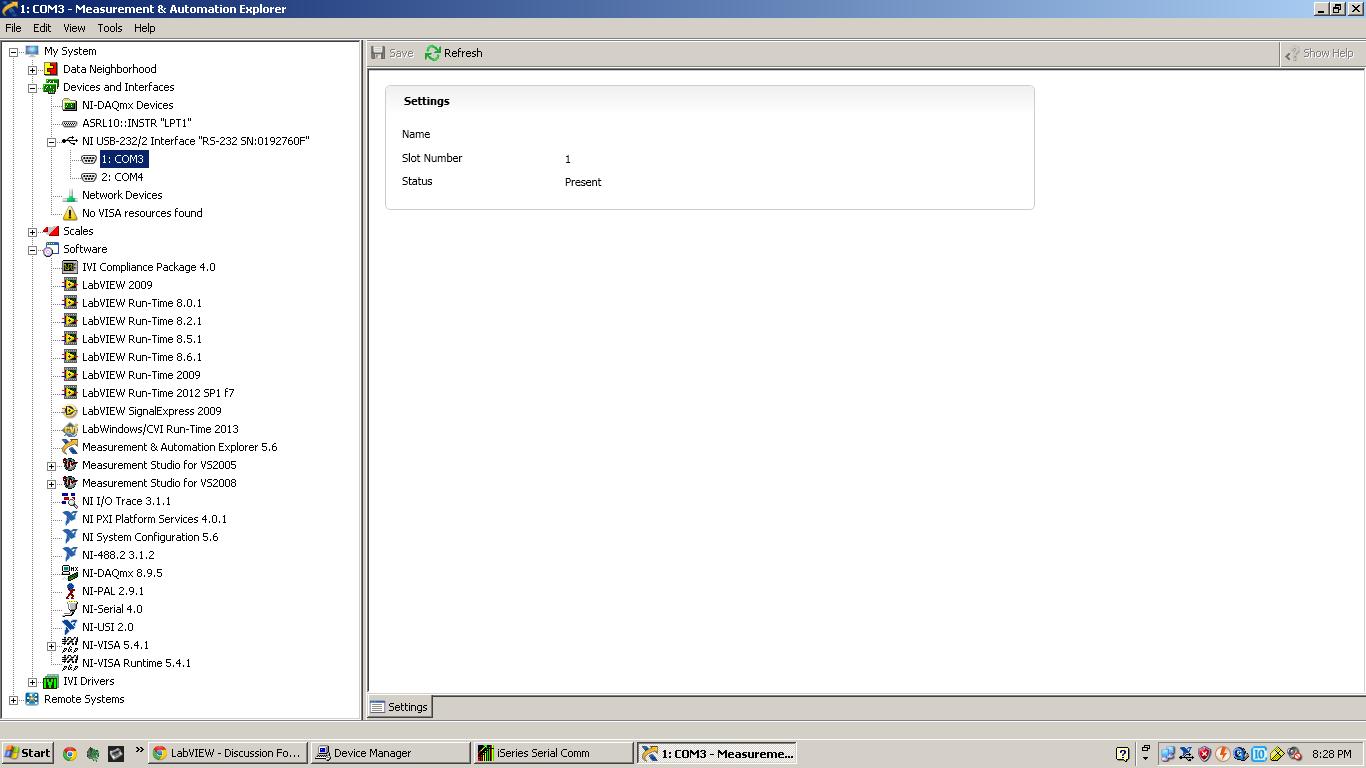
USB-232/2 shows the COM ports but not found resources VISA!
Hello
I use an NI USB-232/2 interface to connect my OMEGA Engineering temperature controller to computer. The thermostat communicates with the computer via hypertermianl and the configuration of the OMEGA software, but can not be detected by OR MAX I've attached a screenshot of my MAX of NOR. I could see the two COM ports, but I can't see the VISA test Panel.
My problem is similar to the post problem OR USB-232! I tried the solution for uninstall and reinstall NI VISA both NI Serial, but still does not.
OR Labview 2009
OR MAX 5.6.0
NEITHER version 4.0 Serial
Version NOR VISA 5.4.1
Temperature controller: Omega Engineering CNi1644-c24
Spoke engineering application NOR two days, no solution. Can anyone help? Thank you!!!
-
I'm trying to set up a 'writing' (inside a case structure) function when a boolean is set to true for writing certain values, however, I can't work properly. The first problem I get is that labview automatically inserts the nodes of comments. Another problem I am getting is the previous written function series instead of the most recent data points (this happens with and without comment nodes). I left the structure of the continuous wire case in attachment. Any ideas? (The background of this program is for the automation of a Lakeshore 331 Temp controller. I'm under various structures case out of a single Boolean flag called "Temp." stabilized When this indicator lights as true, loop, crosses a csv file that provides the data for this "write" function that I have a problem with. I want this car writing to write the data on temperature controller when the most recent data from the csv file). I joined the program and the csv file that I use.
Thank you
Matt
Find nodes in comments is because one branch out of something in the entrance of the same logic. It's like using x to solve for y, but x is determined by what is there. You should know Y BEFORE you can solve for X so labview trying to solve this problem by adding your comments nodes.
Specifically, you have an indexed number power of the upper part to the loop used to set the target time on the time elapsed VI, and using elapsed time? A Boolean to determine the number of iterations to perform the loop before.
Here is the simplest example of what you are doing.
You should look for shift registers and how they work. All the data you want to save to the iteration of the loop iteration to put on a change of logic register.
-
I'm tasting an anlog out using NI PCI-6220, thanks to a BNC-2110.
The signal can be chosen to be bipolar recommended (-10 V to + 10 V) and unipolar (0 to 10 V) and origin of a LakeShore 336 temperature controller. The manual States the following:
"" Non powered analog outputs are not designed to provide the heating power and even if they are little protection, should not be used to drive less than 1 k Ohm resistance ' "
I intend to connect the output of the instrument directly to the BNC-2110, but now I am wondering about this k Ohm 1 thing. How will I know what is the resistance of the instrument entry?
No right, no worries.
I'm sure that the bias current is the minimum quantity of currnent which is necessary to get your signal through ADC in the acquisition of data and MUX. Still, you shouldn't have any problems here.
-
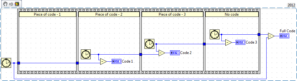
How can I measure the Max delay
Hi guys,.
I'm trying to add the module to the pulse to my VI. To do this, I guess I need to measure delay Max.
In my class VI, I have some instruments of the current driver, LED, spectrometer, camera and temperature controller. In addition, current is the variable I can change all the time during the execution of the VI.
I was wondering how can I measure the delay between the one and the other, and when I change the value of the current, how long will take to capture the right data
I knew that the number of cycles to measure VI all the time but how can I do for several parts
Thank you
Time required for the execution of some code can be done using 'Tick counts' now if you do not want it for full code but you want for specific elements of the code, then you must use the same function (i.e. "Tick count" separately for each section of the code.
Maybe you are looking for
-
How can I return my Skype account has been hacked!
Hello I have a Skype for my work account and some hacked my Skype account in 18 Nov and it changed my mail Skype please guide me what I have to do?
-
LabVIEW locks on DLLs at startup of c# openfiledialog.showdialog)
I'm pretty new to .net connectivity, but I have a dll with a class that when built (using the constructor of node) running my windows form. public class RunForm{public RunForm(){Application.Run (new Form1());}} The form opens and it works fine until
-
How can I get my music on the mp3?
Hello I tried to organize my music on my Mp3 player to play the way I want to play, but it is difficult... I do it through my laptop with the USB. I'm doing it wrong? Please, is there guidelines, I can follow to a resolution on this issue? Thank you.
-
I got the error message 'the expected version of the product was not found on the system' when I was installing Microsoft Office Professional 2003 Enterprise Edition (Microsoft Office Outlook 2003 with updated business contact to update Manager) Serv
-
I have to open the computer to clean fan cooling on acer aspire 5738zg?