Digital constant empty?
It is more of a thing of aesthetics than anything else, but I'm looking for an analog/digital the 'empty string constant.
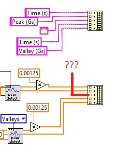
I'll save this data in a file with the 'write to spreadsheet.vi"the array of strings on top will be recorded first as a header for the data that is in the table below. I would like to separate the peaks and the valleys with a column empty and would rather not only a giant column of zeros.
There is no such thing as a digital void. I suggest that you all just to all convert to strings.
Tags: NI Software
Similar Questions
-
Rebel t2i digital display empty
My Rebel T2i has a problem where the screen is empty. The backlight lights up but no menu or fonts of any kind. I was wondering if anyone has had this problem and how it was fixed. Many people with this problem but no result that I could find. Probably don't bother to send repair since the cost is almost what the camera worth?
Thank you
Ed refers to the fact that the 'Info' button to scroll through a series of things in option, you do not want to have displayed on the LCD... and a choice in the cycle of the possibilities is to display nothing at all (screen would remain offshore).
BUT... pressening the 'Menu' button, you have to always bring up the Menu (even if the screen is normally off, it will come to view the menu.) (Provided the camera actually has power and lights up).
If she didn't come... ever... then something is broken only one service can fix.
-
LV2010 novelty: constant digital DBL
I like how there is a new element added to the digital palette in LV 2010. It's a digital constant already set for double precision representation. Previously, you had only a constant digital integer. If you wanted a double, you will need to file the constant digital blue integer, then go through a right-click to change the representation of the integer to double.
Thus, it avoids a boring stage. It is very good.
But I have a question, when context-sensitive help is show for this item from the palette, what is the "(4800)" average in parentheses?

Four digit after SubVIs refers to the model of part of the connector of the Subvi. I believe that this number appears only when you have active script. The valid component of connector beaches range from 4800 to 4835 (someone correct me here...), where 4800 is the single pane terminal connector.
-
Use scripts to create digital orders without button increase/decrease
I'll have fun using scripts to do things that were once "impossible", like the creation of a cluster programmatically in a list of variable names and their types associated with (use in a later program).
When I create a digital control on a front, she has the visible increment/decrement key, by default. I wanted to create controls without this feature, but I could not understand how (or even if it is possible, but I don't see why not).
Any ideas?
BS
Just above the digital named menu item is the one you are looking for: digital
Use the digital constant digital control for Style and class.
-
74F283 sometimes gives wrong output on digital probes
Hello
I have strange problems with the sensors showing the wrong exit. I am designing a CPU, and what is happening on a design more complex and now even on a simple.
I am running:
13.0 Multisim education Edition
Application version: 13.0.0 (13.0.632), database version: 13.0.a
Build date: Saturday, July 13, 2013, 19:42:19
I'll be sure to include a copy of my simple circuit I brought back a multipage ALU 16 bits of 74F181 and 74F182 of an Adder 4 bits using a 4-bit Adder unique with fast include, 74F283.
The installation program:
I have 9 bits go to the entries. They are made of SPDT switches, each wired to VCC and ground, selectively.
The first four "strands" or switches (Q, W, E, R keys) control A3... A0,
The second of four switches (keys A, S, D, F) control B3... B0,
The space bar control Carry-In.
I also 3 series of XOR (74F86) switching each of the inputs and outputs on a selective basis.
1 key allows to reverse the input bits A,
Press 2 to reverse the B input bits,
3 button to reverse the output bits.
The four bits of the sum and the Carry-Out bit are each thread to their own digital logic probe (PROBE_DIG_GREEN).
The problem:
Exit lights are sometimes wrong, but the way that simple I know how to reproduce the bug is as follows:
Load the file. and run the simulation.
Press Q to switch the MSB of the seized A.
Watch the lights of the probe. They're probably showing an inverted output.
Press 3 to reverse the result.
See the same lights.
Press 3 to delete (UN-invert) exit.
The output is corrected as it should have been from the beginning.
Alternatively, press space to show lights crazy and 3.
You can compare this to allowing the LSB of the input A (R key) instead of the MSB (Q key) and see how it is supposed to work.
Why does this work? I'm doing something wrong? Is this a bug with the software? Y at - it update?
Help, please!
-Richard Collins
Student in electrical and computer engineering at SUNY-IT
Hi rich,
I replaced your switch with a digital constant interactive, it is easier to see the digital input as the bipolar switch. You can find this part in the in the Group of 'Sources' on the family of "Digital Sources". Your scheme lacked a digital pattern, it most cases this affect the circuits, but from time to time, he made another, the modified file is attached.
Also attached is an Excel file with the conditions you described and the exit, I had, I don't see a problem with the logic of the circuit. Please let me know if I'm missing something.
-
Good afternoon.
I use a C library for programming an application in Labview (I use the call library function). The problem is that I need enter a NULL value as an argument within the function. Someone can tell me, how do I create a digital constant NULL in LabView.
Thank you very much.
Best regards
Norbert is correct. A simple constant I32 zero will work. Just make sure you pass the value by value rather than pointing to value in the configuration of the node library function call, so that you pass the value zero.
-
accuracy of digital data from LabVIEW
Hello!
I have a question about the accuracy of data, Labview, is perhaps a silly question, but it drives me crazy.
If I use a digital constant and I put for example 1 (I mean 1E-6), it looks like 1E-6 but I found that it is not really 1E-6, actually if I raise the precision and I use 17 digits, 1E-6-9, 9999999999999996E-7.
Could someone explain to me what is happening for digital data?
Thank you
It is one of the most frequently asked questions ever.
The trick is in how computers represent floating point value. I remember a lot of right answers already given in the forum, but I am not able to find the most comprehensive and clearest.
For example, one of the answers is here.
-
loop for and while loop with empty table entry
Hello
I have a question with loop and loop.
When a constant empty array (zero element) is connected to the loop For with "allowing the index", there are no interactions performed in loop For. But, if the loop is replaced by any loop, no problem.
LabVIEW 2010
Hello
It is ok. I have no problem at all.
For the 'loop' For when you connect the table thanks to indexing, the number of iterations is set to the size of the array. The iteration number assigned to N (in your case 10) is ignored.
For the 'While' loop the number of iteration is defined by the Boolean Condition and the size of the array is ignored.
Paul
-
How to display 8-bit constant?
I want to have a 8-bit constant in my scheme of masking... the starting value is 01010101... However, labview clips the MSB 0. I guess it's a parameter? Help please.
It is a digital constant U8 put for a binary display?
Set the display format of this constant to use the minimum field width, 8 and pad with zeros on the left.
-
I'm trying to turn empty waveform to make a chart seem to have 2 different colors, but I can't seem to enter NaN in my paintings. I tried to use positive infinity, 1/0 and NaN in a digital constant, but they are all defaults to ~ 2.25E9. If not, how can I do this?
Are you sure that the representation for digital is set to double? 2.25 e9 is close to the limit of a whole of I32. I have not had any problems with LV 8.5.1. If I have a constant defined for I32 and enter NaN, it automatically converts the constant DBL. If it is part of an array, it does not convert automatically.
-
Determine if an integer is a floating-point number
I want to create a program that when an integer is entered in the digital constant, a floating-point number with zeros to the right of the decimal point lights up the LED on the front panel. The LED remains off for any other floating-point number. I know I want to use a ride to the nearest function, but don't know where to go from there.
rtufaro wrote:
I want to create a program that, when an integer is entered in the digital constant,.
You want to say CONTROL, right?
You just need a type of rounding. No matter if round you upwards or downwards. If you just around and then compare the entry to the rounded value. If they are equal, you turn on your LED. So all you need is a digital control, 2 functions, and a boolean flag.
-
I'm trying to text on a 16-bit image overlay.
The overlay is successful (using overlay IMAQ Text.vi), but I would like to save this file with the overlay.
I have been using IMAQ Write queue 2. VI to write the image as a .png and writes the image successfully, but not overlapping.
I read this comment about overlays:
Using overlay with a third-party Viewer features:
When you use the functions IMAQ Overlay, a third-party Viewer will not display this information. You must use playback Image Vision of information with application software to display the overlay. To display a picture in a third-party Viewer, you can use the IMAQ merge Overlay.vi, who is a destructive function, which means that it replaces the underlying pixels by pixels bunk.So basically I would like to see the images later on a viewer of third parties, but when I use IMAQ merge Overlay.vi, the result is no longer the 16-bit image, I need. It now becomes an RGB image. Any suggestions on how to get a 16-bit image with superimposed text I can see outside LabVIEW? Thank you.
Hi jmeyer,.
I think that's what you hear. Take a look at the screenshot. When you create a constant, or a control on the entry called Pixel color value it will create a dialog box that lets you choose a color you want to use when you click the command/consatant. If you want to enter the actual value of the U32, you can replace this with a digital constant/control and enter the direct number you need.

-
Hexadecimal string to numeric value
Hello
I have a really (I think) a fundamental problem of trying to convert between a hexadecimal number to a 'digital constant' value so I can calculate certain things.
The situation is: I'm able, a VISA series, a distance of an ultrasonic sensor reading. His current reading in an "indicator of string" ordinary put to a hexadecimal display. About 50 cm from distance with the ultrasonic at a wall sensor, I can measure "0032" as my display hex - what is optimal, 32 in hexadecimal is 50.
However, my problem is, how do I now go to the conversion of this 0032 in hexadecimal in a usable digital/decimal numbers?
Thanks heaps for you help.
Nick.
Typecaset 2 bytes of string to U16, for example as follows:

-
Resetting a load with Arduino cell
I use a curcuit to load with an Arduino Mega cell and ordering an operation with LabView. I would like to create a tear for the load cell button as a scale would have. To do this, I need to read the analogue value and then set this value to a variable, such as 'x', when you press the reset button. X then becomes a constant that the analog signal of the load cell subtracks. I don't know how to define a digital constant using a business controlled by a button structure. I think I can make it more difficult to do, but I'm stuck and would appreciate an overview.
Try this, I did not code the arduino active so I can't run it.
What he must do, it is the pulse mounted pressure that reset button has the value of the output current to a value of zero.
I just do it quickly so no warranty! -
Hello
My problem must not be too serious. I receive a text in a file that I want to display on the front panel. I have to refresh each turn of the While loop. The problem is that I find myself with my text 100 times in my indicator. I would crush my text all the rounds of the loop.
Anyone have a tip?
Thank youAn unitialised shift register will remember the value of the last time that the VI ran. If wire you a string constant empty at the beginning of the shift register it clears the value in the shift register each time, so it will contain only the result of the loop and not keep adding to the value of the last run.
Who should fix it

Maybe you are looking for
-
Satellite L300 crashes when the AC adapter is plugged
As long as the laptop is running off the battery voltage, it works perfectly.The moment where that I plug in the power adapter, it crashes. If the laptop is turned off, the adapter can be plugged in and it will charge the battery as usual.The adapter
-
Drive Ext. hard leaves no PC startup
I have connected a new HD post yesterday to my PC and it saved my files etc very well. But when I turned on the pc today, he got as far as the screen of the dialog and froze. I tried to settle things in the bios but nothing helped. I have read the ma
-
x476dw: X476dw lack of print head...
This machine, Officejet x476dw MFP, is less than a year. I am only my second black ink cartridge and my original color cartridges. The machine does not print and tells me that my heads of installed printing arew missing, undetected or incrrectly. 0x
-
After addition of updates last night, my computer doesn't "know" Google.
I can access sites that I have bookmarked, but if I try to Google, anything I get the error page. This happened after several updates were installed yesterday.
-
Serial number for CS5.5 not accepted. Need of 24 digits. I have DWD + 18 digits. [was: stay honest]
So, after buying Dreamweaver CS 5.5 in 2007, I needed to upgrade a Macbook 2008 ProApparently, after 30 minutes, a phone call from 20-minute chat session and another cat for 40 min with Anne online.Adobe solution is for me re buy the software, not ye