Digital entry at RPM
Hello!
I'm new to labview and I have a problem, please help me...
I have a Picoturn that measures the turbine RPM. I connected the digital output of picoturn to Port 0 and port BNC-2110 D.GND. The NLC is connected to the card M-Series PXI-6251. The DAQ Assistant, I make 1 and 0 when I run the turbine. So I connectedd assistant DAQ "Boolean to digital convertor" and then plug it into the digital waveforms graph, but I don't see anything in the chart of digital waveforms.
I don't know if I do it right or wrong. I just need rpm from there.
Tags: NI Software
Similar Questions
-
I want to make a WordPad document that contains several tables of numerical data. To save a lot of time, I'd like to WordPad to add some digital entries, add up the number of times wherever a number took place and other things like that. Is this possible or do I have to use Microsoft Works?
Hello
WordPad is a treatment basis of text which is included in Windows. A word processor is a computer program that you can use to create, edit, view, and print text documents.
See also:
http://Windows.Microsoft.com/en-us/Windows-Vista/using-WordPad(Applies to Windows XP)
-
Problem of current drawing of digital entry into PCI-6220
We have card NI PCI-6220 mounted on card PCI-Raiser in a windows PC mini. We are using 8-channel digital input P1.4 - P1.7 and P2.2 - P2.5 to take a few entries of our entry card.
When the computer is turned on then everything works well and we get of the digital inputs in Labview. The problem is that when the computer is off the digital inputs on current drawing of early card PCI-6220 and due to this voltage regulator IC on our card entry begins to heat upward.
This problem occurs only when the PC is turned off, in a State that everything works fine.
We will be grateful can anyone suggest a solution to our problem.
Concerning
Magalie
I'm not familiar with this part OR special. But maybe there is protection on the output diodes. Usually, these diodes are connected since the entries on the power rail.
In case the power rail is 0V (or below the input voltage supplied in them), the LEDs will be put and feeding current in the power of the PC rail, attractive and current of your external device. If this unit has a push-pull, HIGH level output configuration there will be excessive current from the power supply where the outputs are short-circuit or almost short as it will be in the configuration described above.
I have no immediate solution except for additional hardware as the optocouplers, the outputs of your device from the inputs of the unit NOR the decoupling.
-
Several digital entry tasks by unit
I'm a noob DAQmx here and I have a few general questions about the architecture of task on a device. I'm trying to create two tasks of DI with a portX associated on the same device. When I try to start these tasks the other always up a resource-200022 error.
I even have two tasks for digital on the same device?
Not if they are two devices timed. If you do not use hardware timng, combine the channels in a single task.
-
9205 digital entry into Compact DAQ sistem
I have a Council NI 9205 and I want to use the digital input to acquire a digital fashion Laser diffuse sensor signal, to measure the speed of rotation of an electric motor. The problem is that I have not access to PFI0 in terminal mode of spring. NOR Max I can only receive analog signals. Thank you!
Hi Padeanu.L,
You are right that it is not possible to use PFI 9205 MAX line using the DAQ Assistant. However, it is possible in any programming environment that you prefer (LabVIEW, C, etc.). The PFI line cannot be used as a digital task, but it can be used with counters (edges of County, period, frequency, etc.). For example, in the Counter - County Edges.vi example, you can set the input terminal/9205DeviceName/PFI0 and the meter/ChassisName/_ctrN, where N is the counter that you want to use. The underscore character counter is because the 9205 has only one PFI line that does not support all modes of counting cDAQ, which is also why he does not for you in MAX.
-
Issue of digital entry behavior
PCI-6143 with wheel wired to PFI0 & PFI1. LabVIEW pgm written in 8.5 full. Source code works well (on other Web development pages
computer with USB-6211 card) but hangs, as is eating 100% cpu time in the destination computer. This machine it must run on a LV 7.1 installed and some 7.1 executables. I installed DAQmx 8.8 on this machine with LV 8.5 support. I'm trying to run the executable on this machine that LV 8.5 is not installed.
If I enter MAX, select the card and run test panels, I get conflicting results. If I choose digital IO on both channels 1 or 0 I constantly receive all 8 lights. There is no signal. But if I'm going to count, use the trigger channels and count the edges I activity. Am I missing something? I need to remove these problems before you start to screw up my source code to find a bug that does not exist.
-
Hello
Is it possible to trigger action digital input using the signal I want to measure? In the example:
I want to measure PWM on P0.0 after first rising edge PWM on P0.0, but using only this line P0.0 (no PFI in use, only one used digital entry).
IM using X SERIES USB-6353.
Some DAQ cards can trigger on analog edge of the signal you want to measure. If a DI data extraction, it is possible to select only the PFI or similar as trigger. What is your application? What you want to achieve?
I can imagine you could workaround: record streaming samples of DI and do a SW trigger in your program, so you can get the same samples prédéclenchés (as in a digital oscilloscope).
-
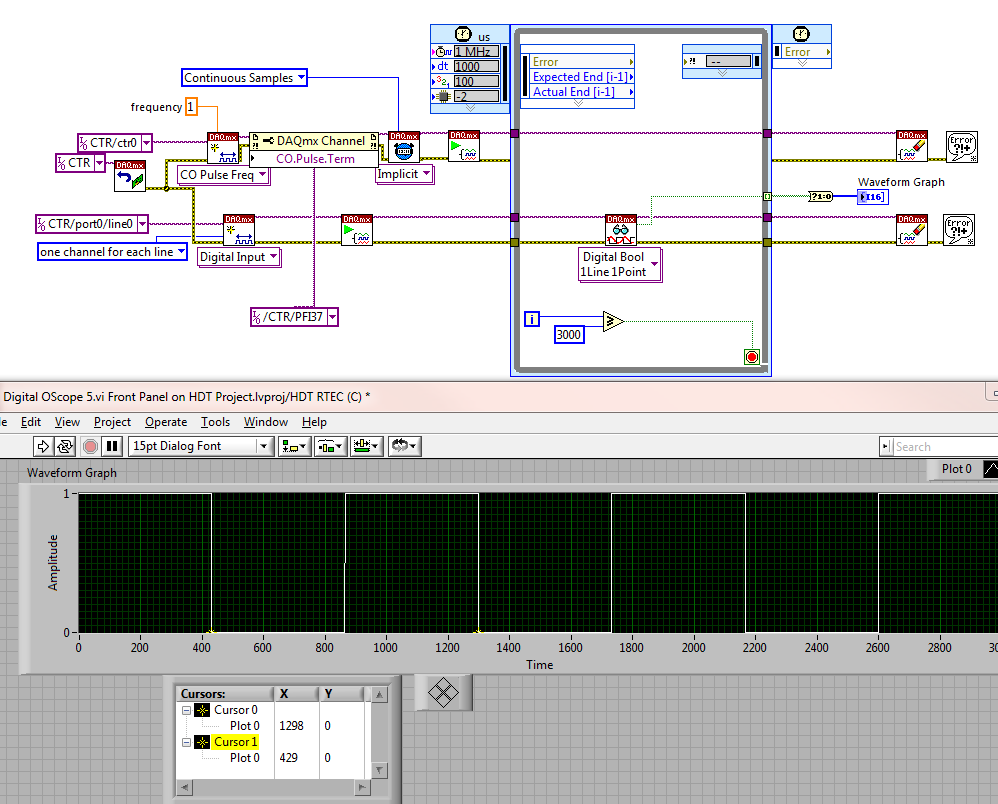
Cannot make digital scope of work
LV 2010, RT, PXI-6602
All I want is a simple digital scope to watch a digital signal which comes out a COUNTER and to judge if another part of my software works.
I struggled all day trying to make connections and finally abandoned - LabVIEW just won't do.
So, I managed to find a cable and get the connection through the material (oh - the horror!).
I start a course of meter.
I directs the output to a specific terminal.
I wired (with physical wire) terminal on a DIGITAL INPUT port.
I made a spot to read than digital entry port.
I used a timed loop to read that entry port a bunch of times.
Then draw the results.
No matter what I do, I read a different frequency than what I'm asking.
He's still 85-90% of the period during which I was expecting.
For example, I'm sampling the port here at 1000 uSec or intervals of 1 mSec.
A check of the END TIMES, or the State FINISHED LATE shows absolutely no error.
But look at the transition of a parcel is sample 429, the next is in 1298. That's a difference of 869 samples or 869 mSec.
If I try to 10 mSec, instead of 1 ms, I get 134-45 = 89 or 890 mSec
If I generate 10 Hz and sample to 1 mSec, I get 138-48 = 90 or 900 mSec
So, which one is lying to me?
Is it really generate 10 Hz and I am in a position he bad?
Or am I just measure and it generates really 11.1 Hz when I ask for 10?
For example
-
Problem with the digital data to write VISA function
I have a GE's PowerPC that is running on the VxWorks operating system. I have a tornado application where I run my C code to generate a file .o & .out, then I empty image .o files & .out for PowerPC via FTP, now I need to communicate with PowerPC of LabVIEW (via serial communication using VISA vi) using the VxWorks controls. When I enter orders VxWorks in LabVIEW
That is to say for Eg: 1 > ls --> the contents of a directory list IE .o & .out files. The problem I'm facing here is, when I run the vi, I am able to read the file in the box to read the string but keep files on speeding up juice,
2 > ld <> --> load a module object in memory. I face the same problem here.
3 > then I need to type the name of funtion main c program, after which I can give input to the program.
4 > I need to enter numeric data as inputs to my program. but the write VISA function accepts the only input string and read VISA function gives only out of string... I want to give digital entries and read the digital output. Any help would be appreciated.
Hi Luke,.
You can try with this reliable hyperterminal VI.
-
simultaneous monitoring of the digital input lines when executing digital writing tasks
I'm writing a multithreaded application in C on Windows 7, using the 9.6 DAQmx API and device USB-6509. This requires that we constantly monitor several lines on the 6509 for entry, digital using the change of the device detection feature. You must also write the digital output without having to stop monitoring the input rows. It is very important that the input rows be monitored continuously for the duration of the project.
In the DAQmx manual reading, it seems that it is impossible to make a digital reading as well as a digital writing occurs, even if these tasks are performed in different threads. (The same I understand, that it is impossible to have several tasks of digital entry running simultaneously.)
It seems that it would be possible to launch the task for reading (configured with the change detection), to pause playback, start the writing task, pause the task of writing, and then re - start the task of reading. But - and this is the important part - for the duration of the writing task is running, is it possible to configure it to the task of reading will always monitor the lines, even if it's just stores the data in the buffer for these periods? The key is that the data will be lost.
Thank you
Danielle
Each channel is independent. If you can get the input data that you export a value. You need not make a break each task. The two tasks are parallel.
-
I would like to have both an array of 8-bit Boolean or a digital control formatted to be able to control a single line Hex. That would give the user a choice of data entry there in digital (entry of value) or binary (by clicking on the Boolean control). How can I input to a control switch.
Thank you
Jim
Your stop button does not work. Create an event of value has changed for the button stop and put the terminal in case of the event. Wire to the terminal of the stop button on the time stop the loop.
[Rats! Submitted too early. You don't need a structure within a structure of the event from the event. Create events for each control. See attachment]
-
Digital inputs only noisy when the laptop is plugged
I had problems with loops of Earth and power supplies for laptop in the past. But it is the first time I got it so wrong that it makes the digital inputs which are both related to the ground and the debounced software cannot be used.
It is NOT material OR. It's a DT9816 of data translation, a USB DAQ Multifunction with small budget. The laptop with the problem is a refurbished Dell, with a very obvious not Dell PSU who throws to the top of the warning in the BIOS and scales back from the processor. (Danger Will Robinson!)

The problem with the digital entries shows only upward on the Dell when it is plugged into a power outlet. On all other machines and with the printer unplugged Dell, digital inputs floating. But those that I have attached to the Earth is rock solid and work very well.
What surprises me is more than the noise is so bad that even tied to the ground with a half second debounce, I get always false triggers. I have not brought to power, but considering that it sounds really loud, I suspect that it looks pretty bad.
I think I'll try a powered USB hub. If this does not work, then I think that the customer will have to replace the power supply on the laptop.
However, I was surprised. I used a lot of USB DAQ hardware, and it's the first time I've never seen a problem like this. The NI USB 6002 I tested on this same laptop does not seem to show the same problems. Even if it is true that this is a different software and the test was brief.
I'm curious to know if other developers have found something similar in the past.
I can confirm that using a USB hub external powered eliminated the problem of noise in the original post.
Interesting things. I had not seen this before. Now, I wish I had again the NI DAQ USB I had here last week so I could test that.
Looks like I'll use a hub powered on this project. But I think I will recommend always replace this power. Although a lot of noise coming from the power supply, probably isn't good for nothing plugged it... or even sitting near him.
-
Digital input and output problem
Hello:
I do a test for digital i/o:
for a table of the digital signal to an output of data acquisition in the digital input to detect the output signal.
(bascially, it's like a loop that goes outside the material)It's pretty simple, as shown in the attached fichier_1.
It works well.
The manual light switch controls, which means that inputs and outputs are ok.Then I went on the low level DAQ for better speed, as in attached fichier_2.
But it does not work. Especially when I pressed stop to abort the loop, an error has occurred:To speed up, I went to the low-level data acquisition as the fichier_2 attached.
But it does not work. Espeically when I press the "stop"button to exit the loop, the error occurs.Possible reasons:
Requested value is not supported for this property value.
The value of the property may be invalid because it is in conflict with another property.Property: SampTimingType
Asked the value large clock
You can select: on requestI don't understand why the sampling time has a conflict here.
(It is probably just something very simple in data acquisition, but I checked a few examples and did not find a clue).
Hope someone can give me a suggestion.Ultimately, my goal is to make the attached file_3.
In this one, I generate a digital output, and then lead to the entrance.
Then I can take it as a signal to trigger my other task.Note:
I use a similar conti signal to control one of my camera.
I need to sync it with my another task.
So I think to generate a digital output (which share the same clock as the signal similar to the data acquisition device), then put it in one of the digital input.
By detecting this digital input, I can trigger my task and synchronize with this signal similar.
My camera's USB-6211.
I am aware of the latency of USB, but once the value is a constant value, then the synchronization is always good for me.
Actually, I was using an analogue at the entrance of the to do it before, it may work, but the synchronization error is too big for me.
I need to do some calculations/judgment for this analog value, which makes the time difference varies.
So I'm trying digital entry now and I hope that the digital input can trigger my task with a stable latency.Thank you very much
Have you looked at the specs? It clearly states that the digital I/o is a programmed software. You have not any hardware clock at all. The best rate that you could possibly achieve is around 1 kHz and which would have a considerable jitter the nature of non-determimistic of windows.
-
How can I get digital signals (interface UART) with a microcontroller with NI USB-6008?
I have acauired a few analog signals by A/D (3 channels). I put each scanned data on 3 digital output with a microcontroller. I want to see if it is possible to import these digital outputs 3 to a PC via a USB-6008? It's like the connection of the output to the digital input of the USB-6008 and import the 3 channels simultaneously to LabView? Do I need to use some other hardware like USB-8451 and connect the clock of the MCU to USB-8451?
Saraydin,
The digital I/o on the USB-6008 is a software program only, so unless your signals are rather slow, it probably will not work for you. In general, the procedure would be to connect each signal to one of the digital lines on the map and then set up a digital entry into LabVIEW task to read the three channels. If you use a device that has clocked by the digital i/o hardware, you then your input clock signal and use it as the sample for the task clock. Here is a list of USB devices supporting DIO clocked by the hardware. Also, there is an example that comes with LabVIEW, which shows how to do this. You can get to it in LabVIEW by going to help > find examples. When the example Finder window opens, navigate to hardware input and output > DAQmx > digital measures > Cont read dig Chan-Ext Clk.vi.
The 8451 is specifically for I2C and SPI, and would be great if you try to make one of these protocols, but otherwise I would recommend the devices in the list I linked above.
-Christina
-
DAQmx write (digital) works in mode "highlight execution", and not in normal mode
Hello!
I would like to create a simple vi (it will work as a Subvi watchdog in a project) to send TTL 5V 0V 3 seconds 3 seconds, by performing an iteration in a loop.
Use a card PCI-6703 to that effect (beside that I use for the generation of analog static waveform on several stations). I also have a DAQ USB6212 card, and I have test my digital output with this USB card digital input via MAX.
The strange thing is that when I run my code in mode "highlight execution", I get what I want: 5V 3 seconds, 3 seconds, 0V, iteration.
When I try to start it in 'normal' mode, I only see the 5V constantly from the output through my digital entry in MAX.
I know I'm doing something wrong, but no idea what...
Please find attached the vi simple.
Thanks in advance!
Kind regards
Your overall loop time is 3 seconds (3000 MS of waiting). You have a 3 second delay between writing the real and write the value false. But as soon as the false is written, the loop reminds immediately (the second set of 3 waiting operates in parallel to the writing-Delay-Write sequence) so the real gets drafted immediately after the fake. It will be just a blip. So that if you run in the execution of climax, the code goes pretty slowly so that you see the Boolean value False as LabVIEW takes his time data flowing drawing wires.
Put a delay function after your DAQmx write wrong, as well.
Maybe you are looking for
-
Connection of Internet Time Capsule airport
Before buying, I asked the store if this would replace my sky router, they said yes. However, all connections are WAN/LAN, and there is no reference to a direct connection to my BT socket (via a broadband filter). Should I still my Sky router).
-
Firefox 6 browser takes too long to load. Can anyone help?
I run Windows Vista with Norton 360. All software is legal and properly updated. I clean the cache, registry, etc. regularly and defragment on a regular basis. Many sites Web also charge much more slowly than before. Should I remove some of the plugi
-
Error on my HP Officejet 5600 series printer
I have a printer HP Officejet 5600. I was in the middle of printing the other day when my laptop shut down - so now the printer does not printIs not given an error code - just says error printing only - printer does not display an error - just in pri
-
I have a HP 6300 Pro workstation. I am building an image of XP SP3. I changed the storage IDE, installed the o/s and all the drivers and took an Acronis image. I'm at the point where I want to load the driver AHCI and flip the BIOS default setting
-
How to restore the keyboard shortcuts
original title: keyboard shortcuts I lost all my keys shortcut, such as Ctrl + C, V, F etc. All applications. How can I restore them please.