digital input voltage measurement
Hello.
I develop software for a test bench.
(the material has been developed in the past by someone else, and I have to use this material now)
I have to read some digital data with one nor usb 6501.
I measured the voltage on pins levels and realized that to logic 1, I get about 4, 7V, logic 0 about 3, 5V (who, after having converted to digital, is always 1).
You have an idea how I could fix this?
I thought that if I could somehow put the analog value of voltage on the PIN, the problem would be solved, but I n ' not know if it is possible.
Thanks in advance.
Katona
Hello
the 6501 low input voltage (false logic) is 0.8V and high voltag of entry is on the order of 2.0 v to 5.8V. You must use an electrical circuit or device with an analog entry order to solve this problem.
What do you think of "Schmitt Trigger"
http://en.Wikipedia.org/wiki/Schmitt_trigger
Concerning
Rüdiger
Tags: NI Products
Similar Questions
-
How can I measure the time between the two edges of successive increase, using digital input...
Hello
I'm trying to measure the time in seconds between each two successive rising edges on a digital input.
So far I managed to detect the rising edge, increment a counter at each rising edge and take the time during which the increase is edge
all I need now is subtract edge currently rising from the previous era of edge rising to calculate (T), which can be 1/frequency and display in real time for the user.
but I do not know how to do this

Can someone help me please!
Note: while I am in a position varies between 200 ms - 2 seconds
-
How can I measure the time between each two successive increase edges, using digital input?
Hello
I have tried two measure the time in seconds between each two successive rising edges on a digital input.
So far I managed to detect the rising edge, increment a counter at each rising edge and take the time during which the increase is edge
all I need now is subtract edge currently rising from the previous era of edge rising to calculate (T), which can be 1/frequency and display in real time for the user.
but I do not know how to do this
Can someone help me please!
Woah!

Sorry Apok, but your code becomes much too complicated and salty. I don't think that all records to offset or Boolean conversion/operators are necessary at all.
If you want to measure the time between two keys so it's another (much less complicated) way. It simply records the time when press button in a registry change, then compares the two.
-
A voltage divider will be enough to read a 28V pulse in NOR-6251 digital input ports?
Hi all
I am a scientist life sciences that attempts to read a 28V 4.2mA pulse signal sent from my operative box animals in my NOR-6251.
Sounds like a voltage divider should do the job. But I would be aware of anything else that my card OR not to burn? And should I be concerned about the current entry in the map OR?
Thanks for your help!
Hello
Research on page 7 and 8 of the Datasheet of NOR-6251 , it shows that the maximum voltage is 5.25V, so use a voltage divider to make 28V up to 5V and you should have no problem providing you can guarantee your 28V source will always be to 28V or less and your resistances are fairly accurate. Under no circumstances should provide you more 5.25V to the digital input.
The only concern you have on current is that the resistance divider is not affected by the impedance of the digital input which is little likely (datasheet says max 250uA), so if you use resistors around the range of 5 to 50 k, you should be fine. Also, be sure your part of wiring resistance as if she had the wrong way, you will have a great chance to break the map!
I hope this helps!
-
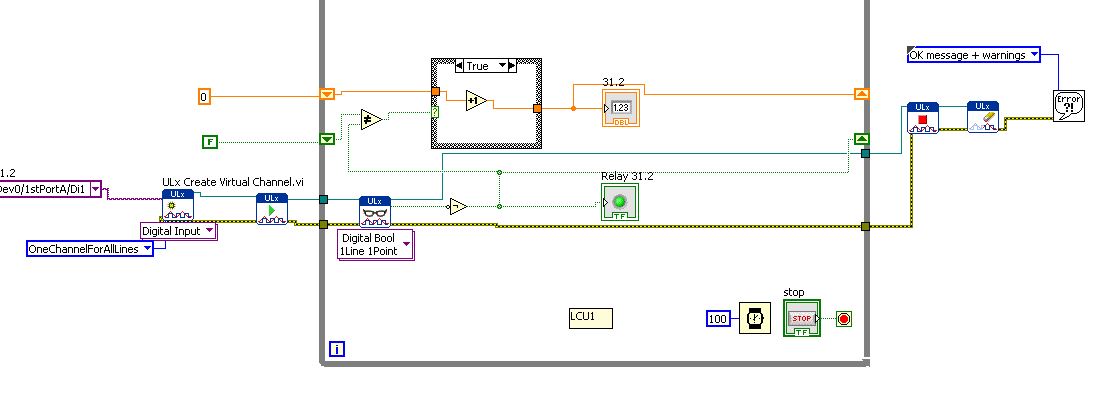
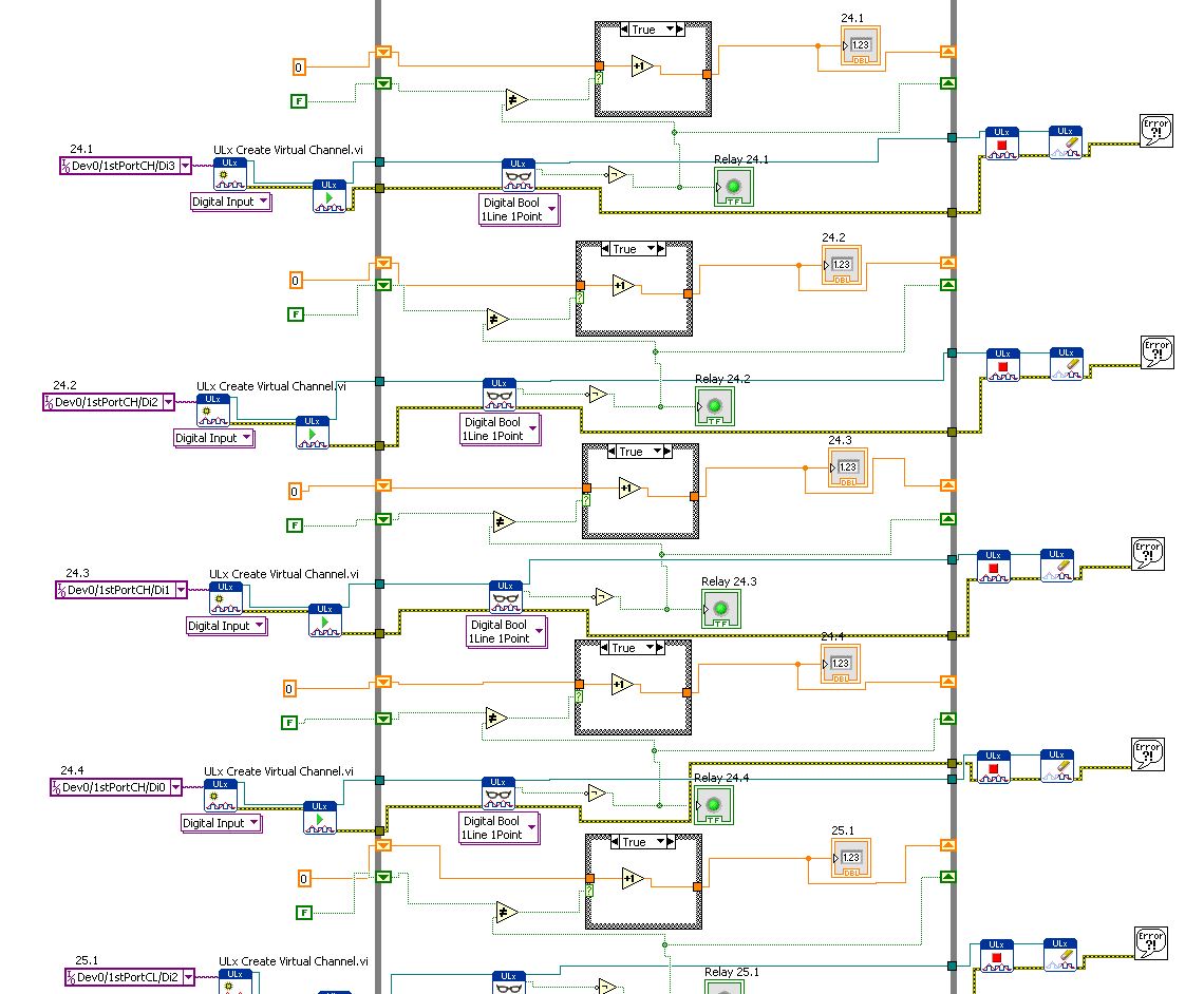
How to combine several digital inputs for playback?
Hi comrade Labview users.
I just started using LabView and I am very new to it. I know him understand how it works and you have something to work, but I need to be more effective.
I use DIO96H - USB DAQ Measurement Computing, which includes 96 digital inputs. I use the DAQ to acquire the activations of relay and record the number of times the relays flips.
Basically, I created a digital input read and then copy & pasted 95 times... it works but I know that's not the best way to use LabView.
How can I change the digital input (Di1/1stPortA/dev0) in multiples so that it iterates through all 96 channels without copying and pasting the same pattern over and over again?
Leon
You have the correct polymorphic instance for playback? Once again, for the material OR it would be a NChan Read. There should be a similar choice if I remember correctly.
-
Hello
After reading everything that specifications and manuals, I decided to ask a general question.
In the data sheets, user guides I've read, in general, there are two warnings for DIO:
-Do not connect the outputs digital circuits which operates above the limits.
-Do not drive the line with tensions outside its operating range.
Generally speaking they tell me I need to know when dealing with output and voltage when dealing with entries. So I have this question, can I wire a power supply for digital inputs directly without exceeding its "beach of normal operation and without any protection circuit? In fact, my feelings, this is not possible. But why certain documents produced clearly mention that the impedance internal inputs while that of others is not clear those? How can I determine if I can connect a signal directly to an entry (for example USB-6525 indicates a current limiter circuit, but I don't see a clear explanation in the datasheet USB-6251)?
As long as the input voltages are within specified limits, no damage will be the DAQ hardware. Logic devices often have two lines of non overlapping input, one for low input and high input. If the input voltage lies between the beaches, the performance of the device can be unpredictable. Also, check your power supply to make sure that this doesn't not exceeding when turned on or off as that could exceed the DAQ limit.
Lynn
-
Hello
Is it possible to trigger action digital input using the signal I want to measure? In the example:
I want to measure PWM on P0.0 after first rising edge PWM on P0.0, but using only this line P0.0 (no PFI in use, only one used digital entry).
IM using X SERIES USB-6353.
Some DAQ cards can trigger on analog edge of the signal you want to measure. If a DI data extraction, it is possible to select only the PFI or similar as trigger. What is your application? What you want to achieve?
I can imagine you could workaround: record streaming samples of DI and do a SW trigger in your program, so you can get the same samples prédéclenchés (as in a digital oscilloscope).
-
Hello world
I use an NI USB-6501 and I'm trying to understand how to read the entries.
I used this card to generate output using the example vi write Chan digging, it works fine.
Now, I'm trying to use the example of reading dig Chan vi to read an input voltage. But it seems that, by default, the map reads 5V (a 1 logic) as entered on each pins, even if nothing is connected to them. I tried to connect the output to the input, use a relay to see if it detects a change in the entry, if we send a voltage or not, but it changed nothing. It still reads 5V anything.
Can someone help me understand how to be able to read an entry? This problem has happened to someone else?
Thanks in advance.
Frédéric
If you dig through the data sheet, you will see that there is a 4.7kOhm shoot all digital inputs. So with the floating inputs you will get a high (logic 1).
As Dennis have already said, wire your digital output directly into your digital input. So everything that you set the output that you will read on the entry. I don't know what you do with a relay.
-
Hi all
I meet a scenario where the digital input on my DAQ card channel giving 5V when I measure between the channel and the ground. As a result, I was not able to read the digital signal. This happned in the past, a few months ago and my work around it is to switch to another channel. This time, I feel the same thing using my FlexRIO + OR 1483 module. There are four DIO channels and I have them configured so that came in 2-channel and 2-channel output is. Initially, everything worked fine, but somehow, these last two days, I wasn't able to read DI channels. During the inspection, we discovered that DI (at NI 1483) channels provide 5V.
I hope someone could shed some light on the phenomenon.
Please advice.
BEA
Take a look at the spec, maybe a pull from the top of resistance?
-
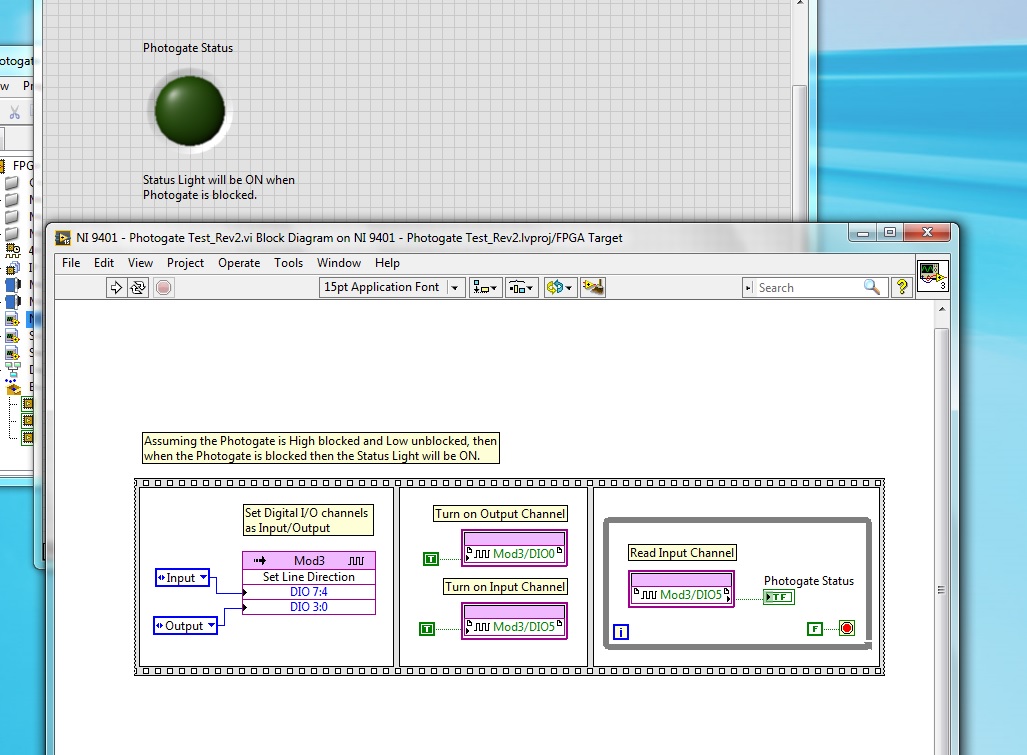
Playback of digital input [FPGA] - NI 9401 - questions?
I'm having some trouble with the digital input NI 9401, which is to have a uniform reading. I have a photogate that power of a digital output is turned off and goes in to a digital input module, but I can't read the entry several times. My LED flashes once and never again will blink until I restart my CRIO or recompile. I have launched the ports of entry and exit, their market and constantly for loop. Any idea what's going on?
Hi Allan,
Why you "light up" a channel of entry?
Writing a value to a DIO PIN is usually for outings!
What is connected to your PIN DIO 5? Have you checked the entry with a DMM measure?
How long the impulses are measured with this entry? Do you really you can see short pulses of light flashing?
-
Hi all
I have to admit that I am inexperienced with DAQ cards (just do simple things in the past). We just receive the NI USB-6259. The plan is to use it for many tasks. One of them is a digital signal to measure at the maximum rate. So far, I have tried ti create a task in MAX - what I've managed to achieve was to measure samples of 500-700 to 1 Mhz using N samples measurment. In order to have 1 Mhz sampling rates, I use an external clock PFI12 (output meter 0 - I put the counter to generate 20 Mhz Signal - 50ns/50ns time Time High/Low).
The thing is - it possible to obtain samples is acquired at 1 MHz with continuous mode? When I try with my current settings I get overrun error - I have tried task ru round trip - first clock generator started, then input digital. and the other way entry digital, first of all - so I guess that this overrun is not due to misuse.
In the documentation it says:
If the DAQ device receives a DI Sample Clock when the FIFO is full,
it reports an overflow error to the host software.
Is there another way to receive digital signals, where a picture lasts about 6 ms and consists of 8-bit?
-
Using the DAQ USB-6009 meter and an analog input voltage at the same time.
Hello
Currently, I'm reading the two channels of voltage with the USB-6009. It happens that one of the channels is the output of a digital coder, and it would be much easier to use it directly to the PFIO entry that is defined as a counter. The problem I am facing right now, it's that I can't use the DAQ Assistant to use the analog voltage to a channel and the digital channel counter at the same time. Once I put the DAQ Assistant to read the input from analogue voltage, I won't be able to add analog inputs. And as I put the DAQ Assistant to use the PFIO as a counter, I can add more entries to read analog voltage is.
I wonder if it is possible to solve this problem using the lower level data blocks? Another solution would be to read two channels in analog input voltage and that the use of Matlab to process data resulting from it, since I was not able to do the counting to work simultaneously with the acquisition in Labview to impulses.
Hope you guys can help out me.
Thanks in advance.
Using a simple wizard of DAQ is incorrect. You need one to acquire analog inputs and one for the meter.
-
PCI-MIO-16-1 shows the digital inputs 1-7 on, without same cable connected
Max, my PCI-MIO-16-1 shows the digital inputs 1-7 as having entries of tension without same cable connected to the Board. No amount of spin with her (to the MAX) seems so he can act correctly in input or output mode. It's true, there are voltages on these pins. If I connect my cable (to a TBX-68 block), I see that it has on $line0 (on port0) 0v, 5v on line7 and 2, 5V on the rest. Trying to put these lines to something else in MAX seems to do nothing. (I also can't control the OD, either.)
This card has tried to get a couple of have Weiwei at high speed. Now that I'm branching out, I found a strange behaviour. Of course, I tried to restart and turn off the computer and turn it back on. Automatic test MAX Returns instantly with a message "transmitted", that gives me hope, even if I don't trust the speed at which it seems to perform the check.
I'm a complete noob at this stuff. Is there something obvious that I might be dominant? Is there a way I can test more deeply that the card works as it should?
The open connections to the TTL inputs are usually detected as logic 1. You are not testing properly. Connect an entry to two gnd or + 5V. Don't let them ever floating.
-
Digital input line showing an entry without connected equipment
Hello
I have a feeling, this is a silly question, but here goes. I have the VI below to read the entry of an analogue of the ADC0803LCN to digital converter through 8 lines.
The DAQ assistant is configured to read a digital input for all 8 lines and outputs in a matrix of LED that outputs then a digital indicator to show the binary value.
However even if I don't have the connected equipment and run the program, all lights are lit and on my multimeter I read + 5V to each line. I'm puzzled why I get an output voltage in each line when 'acquire Digital Input' works and why LEDs are HIGH without input logical proof. Even when it is connected to the material, which runs correctly, it still shows all logical LED HIGH with the release of material would not justify this. Any help would be great, thanks. I'm a Newbie, just to be clear
 , thanks.
Material is - pressure sensor Honeywell Trustability--> ADC0803LCN--> NI USB 6501
Hi beginner,
the answer is shown on page 14 of the Manual of USB6501...
(It is named "PR"
 )
) -
Hello
I searched for centuries for the answer to what I thought was a simple question - the iMac has one digital input (optical or other)?
I know that the headphone port doubles as an analog audio to as well as an optical digital output, but this port also accepts input optical? If not, is it possible to enter a digital signal via a USB port?
I have an iMac (20-inch, mid 2007).
Thanks to all who can help.
AL
Yes exit usb audio and are truly comprehensive external soundcards, they can have any type of entry and exit of the machine to be desired that they have
and if they do a driver of OS x for him it's just a matter of connection installing the driver and choosing the entry in system preferences for being that
If the audio minijack that also take in charge the headset for iPhone I believe support the digital input and I don't know if
Maybe you are looking for
-
Cannot sort more GB projects by name.
GB 10.1.0 El Capitan 10.11.1 Hello people, For some reason, my list of projects GB a blur. They seem to be definitely classified by date. Select "Sort by name" is no longer works. (Or 'genre') I always kept the list in alphabetical order. Workflow:
-
original title: msn games I get "other players left the game" when I quick match failures. It says to click "replay" and select "Quick Match".When I do this it shows once again "all other players left the game". It doesn't let me play Backgammon or h
-
Windows Movie Maker - error message not indexed
When I try to import a video to Windows Movie Maker, I get the following error message: the file C:\My Documents\video\VID00023.wmv is not indexed and cannot be imported.
-
I had to re-read and proof read an outgoing email x 5: () seems that my cursor is in all directions; My cut/paste feature, it is lost in the transfer and the characteristic charm of check is terrible. Just upgraded to Firefox and affect only my hotma
-
How to structure my application?
Hey guys, I'm currently trying to write my first app native blackberry 10, but I have a question on how to structure the app. To clarify this I want to know, here a small overview on important parts of my application: (1) connection (2) list of entri