Digital noise in the output
I hooked up a new computer. Started having digital noise of the output with Logic 9. Never had this problem. I've checked all my sample rate to match. I thought it would be in my Motu hardware, but when I turned the motu offshore and just ran through the output built in logic he was always there. I ran audio from iTunes and the internet in general and the noise is not there. Fair and logical. Biggest problem is he spent on the computer I was using, where nothing was ever a problem. No sound on both. Oh my god! Help!
Guy
Monitor your levels. Make sure that nothing is in the Red of the level meters.
Also, check your volume settings (output) on your computer and LPX.
Tags: Professional Applications
Similar Questions
-
A60 excessive digital noise from headphone/output jack
I have a new A60 (although three or four weeks) I work in the industry of music and must deal with music on the laptop. Everything has been fine until trying to empty to an analog audio output device. Digital noise is incredibly strong! Its there all the time but just touch the double mouse pad the amount of noise.
With a headphones only sound, but not too visible through a preamp, well well its just unusable.
Is anyway around this or should I empty the A60 and buy a ThinkPad?
Hello
I don't know, but in my opinion you have problems with parasite frequency. Please take some info by music experts. I'm sure it can be solved. If you want you can check one my previous assignment.
http://forums.computers.Toshiba-Europe.com/forums/thread.jspa?threadID=6223&MessageID=21596#21596
Good bye
-
OK, here's my problem - I have a set of audio interface Protools Digi 002 via Firewire 400 on a PowerMac G5 I was lucky enough to be given last year. I finally managed to connect my home recording studio system, he wire of mixer etc, but when I listen to the music coming from the outputs of the Digi 002 there in a great cacophony of audio interference, so much and so well, when I mount the system I can move my pointer between two monitors and it plays a different frequency of buzz. Everytime I open a window, Soft etc it is more electronic noise.
He took a while to limit, but after reading this excerpt from wikipedia, it seems that it was a fault common to this particular model until Apple released the revised version of the B of the G5 (?);
' The first versions of the dual processor G5 have problems of noise . The first is ground loop- based interference,[5] that sometimes causes noise seeps into the outputs audio analogue. This bug has been fixed in Rev. B G5.'
and
' Well that the noise problems do not prevent computers affected work, they asked problems for audio professionals and enthusiasts as well, especially for models to liquid cooling, which had been expressly designed as mechanically quiet for listeners. "
Well, that's no euphemism - in fact it makes the mac completely useless for my needs, I need the outputs clean digital noise to send for outboard effects/EQ/etc.
As it was a common fault, I was hoping someone might be able to shed some light on a workaround solution, as I can't imagine recording ground studios just stop until this has been fixed by releasing a new G5?
The only idea that I came up with so far is to buy a transformer of isolation, but I'm not entirely convinced that will solve the problem?
Any help on this would be greatly appreciated!
Thanks in advance
Have you tried CHUD Tools & turn off NAP mode?
The first versions of the dual processor G5 have problems of noise . The first is ground loop- based interference,[5] , which causes sometimes analog audio output sound leaks. This bug has been fixed in Rev. B G5.
The second problem of noise came from his "tweets", which can be triggered by power fluctuations. For example, display or hide the Dock makes a short beep. Many blamed the power supply used in the G5 as the cause, but this theory has never been confirmed. A very effective workaround is to disable microprocessors 'siesta' using Apple CHUD Tools, but this was not recommended by Apple. This noise problem has not set until the generation of dual-core G5s was produced, but it does not affect the model of "Late 2004" (at least there have never been reports). Draw of power fluctuation has been later attributed to the lack of power management features in processors simple heart. [6] Apple eventually posted information bug tweets on its support site. [7]
Although noise problems did not prevent the computers assigned to work, they were problematic for audio professionals and enthusiasts as well, especially for models with cooling liquid, which had been expressly designed as mechanically quiet for listeners.
https://en.Wikipedia.org/wiki/Power_Mac_G5
Just one last note on the use of CHUD tools to disable the 'Nap' on the G5 Dual functionality: restart your machine reactive 'Nap '. You may have already seen this on the Apple forums. Kind of a bummer - although I rarely shut down my machine. In any case, running with 'Nap' off today seems to have resulted in a significant increase in general speed/responsiveness for me (I'm still running the stock 512 MB RAM, with another 1 GB on the way).
«Matthew S.»
-
The output on the sound output box has no drop downs. The audio output suddenly disappeared and when I went to the 'exit' sound in 'sound preferences' the only thing that would show was the headphones. After that I tried a couple of things suggest that 'Helping Apple', sometimes in digital form & everything that happens you can't change for something else. Things I've tried suggested by Apple press help were the "Shift control option buttons & button / stop at the same time." or press the Option, the command, the P & R key as soon as possible after you have pressed the button On. Hold down until after the second gong during a manoeuvre. This did cause the digital option, but none of these 2 is the one I need. Help
Perhaps, it would be useful to know what that is exactly the one you need. Are get you an external speaker output or anything like that. Also, it would be useful to know the operating system you are using.
-
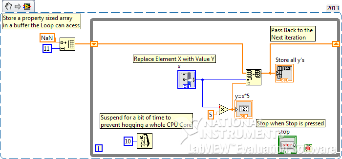
Storage of the outputs digital of an element in a table 1 d
Hi all
It must be simple and easy, but I don't seem to get it. A sample VI is attached.
I have a slider control which I do a manipulation to generate an output of the digital item. I can keep on sliding and get that the output generated, but now I need to store all the possible exits in a 1 d table.
Your help will be very appreciated.
Concerning
Yes quite simple and easy. You missed a few basics about LabVIEW. See the note to the modified VI.
(Also presented as snippette for those who don't mind the commitment of the DL
-
No digital noise will come out, only analog HD is heard through the speakers
No sound from digital driver. Although it seems to work normally, no sound is coming through analog plugs connected to the speakers at the back. Should I change the GET connection__or one cable that converts analog versa__ pilootes or vice
2 drivers high definition digital audio: NVIDIA and REALTek. 1 realtek audio of high definition. They work normally, but internally because no digital noise will come out. Only high definition analog sounds through the speakers. The rear panel of the NVIDEA GeForce 8400 Gs system does not catch digital or taken to the sound system. There are 6 analog for normal sound system. Not digital. I have optimized pc and digital audio and digital experience. Should I buy some kind of jacks or cable analog-to-digital converters or another pile of sound cards just to get digital Pug face now in the speakers. Help, please
If I remember correctly, you have run in a common misconception.
There is no plugins audo on the Nvidia card, nor on ATI cards, instead, they send sound to your analog "sound out" devices (which are paradoxically digital).
And for reasons to ask: what color is taking you connected (both of em)?
-
I recently bought a new computer from desktop HPE-300z, personalized with a card his Creative Sound Blaster X - Fi Xtreme Audio (Windows 7 Home Premium OS). I tried to reach my old Boston Acoustics speakers 'Digital Media Center' system but not sound during the SPDIF selection as the default value. I use the same RCA cable with mini adapter attached to the digital input on the speakers that I used on my old system and connect me to the blue plug clear on the soundcard (according to the documentation on the Creative site). I contacted the manufacturer of speakers and they claim that the speakers should be fine, as long as the signal does not exceed 44K. I tried selecting 44 k in souncard nothing works settings. I tried to contact HP support, but after three hours, they said that my computer and sound card are not designed to generate digital output of soung, who I think is incorrect. The speakers work fine when connected to the analog input on the speakers and light taken green on the sound card with speakers set by default. Please let me know if there are a few additional settings that are required for digital sound or if there is a way to test if there is no digital output generated by the sound card to say whether map whether faulty or not. Thank you.
I contacted the creator, the manufacturer of the sound card, and they explained in an email I received this morning that even though the illustrations contained in the user manual of the map shows the digital I/o as one of the functions of the blue port, this function is not available unless you have the optional digital i/o Module. That's why HP support was right when they initially informed me that the card had no digital output. The problem was with manual of the card that was incorrect, or the less misleading. Thanks to all for trying to help. This problem is now resolved.
-
generate the output waveform on 6259
Hello
I would like to generate signals of "simple" digital square output 3 6259 NI Board of Directors of 80 Hz.
Because of the wiring of my test tool driven 6259 Board, I can't use the output of the meter, but I need to plug into 3 output lines.
I re-used an existing vi and made by a subcontractor, but the generated waveform on my DUT does not have the expected frequencies (although it seems OK on the generated graph). Indeed, there are some forms of square waves, but not continuously. A sort of "pomade" and "elected" frequency does not match the measured frequency. If someone has an idea to help me, I have not experience on labview yet!
Thank you!
You have 4 unique digital States aimed at bike. Each cycle produces 1 full period of each of your square waves. If you want the output to 80 Hz, you must set the sample to run 4 * 80 = 320 Hz clock.
The other thing you see on the scope is that there are short bursts of pulses with parent long time between bursts. The calendar during the bursts are what control tasks. The time between bursts is caused by using the button "run continuously. Also that according to them, you complete vi almost immediately rather than waiting until they run awhile. Put an end to the execution of vi initiates self-cleaning of LabVIEW. These things represent the time brief burst and the ISH between bursts.
-Kevin P
-
24 v digital signal of the event from the host to the fpga power on/off
Hello forums or
Sheet material
cRIO-9074
module or 9472 digital module 24 V output c series
To expand on the topic described,
I want to be able send a trigger to alarm the fpga digital 9472 out that lasts 30 seconds using the operating system time real clock time on the host computer
The way I approached this problem is that
In the loop where the event occurs, if the event trigger is defined then the fgv has a time stamp when the event occurred is sent.
In the loop that communicates with the control of fpga, I write to the control based on the condition that the difference of the current time checked and fgv time is 30 seconds or less, then it will send the value true, otherwise send fake and wait for the next occurrence of the event.
The main problem after implementation of this is that 9472 led does not turn off when the false value is sent to it.
cordially Mzamanstl
Timer Keeper SD is a FGV so that it is written for her, once the event occurs
So if the event occurs so timestamp is stored and then the difference of the timestamp result is<30>
then a true value will be sent to the module of 9472
So basically I want the light and I want to do the 24 v output for 30 seconds then turn off and wait for the next occurrence
I think the method that I test it with is not very good, because I realize other factors that may contribute to this problem, so I think I found another way to test
and I will try it but its will take time.
cordially Mzamanstl
-
Basic measures and the output impedance of the change with PXI-4461?
Hello
I am required to build an audio station with platform PXI OR test.
It is my first experience with Renault. So I don't really know a lot...
The PXI-4461 is a replacement of a former HP audio Analyzer. The measure is quite simple:
1 generate fixed freq signal and measure AC RMS power
2 measure THD (total distortion harmic) at frequency fixed
3 measure SNR (signal to noise) at frequency fixed
4 generate and measure DC signals
5. change the output impedance of 50 ohms and 600 ohms.
If I have a good feeling on which tasks 1 to 4 are feasible. I would like to ask if the task 5 (change the output impedance) problem possible?
If this isn't a work around?
As for tasks 1 to 4, it is possible with out doing 'a sound vibration' Toolkit?
How helpful the Toolbox will be for the tasks listed above (humble).
What should be my starting point learn to manage these measurement with Labview?
Thanks in advance
Hi Hazkel,
Sound and Vibration toolkit will help a lot with steps 1 through 3. This without the Toolbox would require a very high level of knowledge with LabVIEW and you will probably run again for complications. In response to the fifth step, I tried to adapt the output impedance and am not able to do so programmtically. However, you can still do this in hardware by adding a shunt resistor and potentially switch between if necessary impedances. We have an article that deals with impedance matching and a circuit configuration to set the impedance if you are interested:
Impedance and impedance matching
http://www.NI.com/white-paper/3475/en/
I recommend starting with examples that we have already built in LabVIEW to familiarize yourself with the concepts. You will find them by clicking on help-> find examples-> search, then search for your application. Please let me know if you have any other questions.
Thank you
-
Change the output state if the connection is lost
Hello
I use a multifunction USB data acquisition system - 6341 XSeries to control an experience involving a heated hose. I use MATLAB to read a number of analog sensors, and output digital to activate the relay to control certain devices of heating and a pressure relief valve. My problem is if I lose power, someone throws a cable or my computer crashes Mid-test, I want the relay to turn off (IE, return all the digital outputs 0), for reasons of security.
I figured out how to make the default value to the output power up to 0, but I did not find anything describing how to do the same thing if a connection with the computer is lost. Is there a property inside the acquisition of data that I can program to do something like that?
Thank you
Jimmy
The 6341 timer has a built-in digital i/o which is mentioned in the X series user manual in Chapter 6 (pdf link).
You reset the watchdog timer of your software loop - if the timer expires the material past to a predefined State.
I have no idea how it is configured in MATLAB, but in the C API functions used are DAQmxCreateWatchdogTimerTask to create the task and DAQmxControlWatchdogTask to reset the timer.
Best regards
-
read the output of a path of analog output current voltage
In DAQmx if you are unsure of the status of a digital output port, you can take a reading on this subject. When I try this on an analog output, I get an error. Is it possible to query the status of the output of an analog output? I realize that I could follow the State with a variable, but a direct reading would be really handy.
Hello, GIS.
There is no way to read the output in the AO modules without wiring physically the signal to a module to HAVE. You are able to use a variable to read the current value of the output, as you mentioned earlier.
Channels AO multifunction boards, however, can be read through tasks of entry by rounting in-house channel to read ao vs aoground.
Lisa
-
How can I measure the output of a sensor pwm ultrasound using the module or 9403
How can I measure the output of a sensor pwm ultrasound using the module or 9403
Khalil,
When you say 'measure' the PWM signal, exactly what to tell you?
You're looking to measure the frequency or cycle of the signal function? You count the edges of the PWM output increase? Looking to control the waveform?
With reconfigurable FPGA hardware, it is up to the user to define the function of the physical i/o on the FPGA chip. By connecting the signals as Adam suggests your digital pulse will be brought to the cRIO. In your FPGA program, you define the function. You can set a base counter or transfer digital data from single point to welcome you cRIO for floating-point more complex treatment. Example FPGA programs are located in the http://www.ni.com/IPnet.
Hope this helps, please post any additional questions.
-
Is it possible to limit the output of a multi-turn encoder to match a single round?
I use a Heidenhain encoder with an EIB Heidenhain 741. The 741 takes EnDat signals and converts them. I use a program called LabView of Heidenhain poll Positions. The encoder outputs are incremental and absolute. The outputs take into account after a revolution and I would go back to 0. The program uses a table 1 d with quad 64-bit for the absolute value and an array of 1 d of 16-bit value for the incremental values. I'm trying to convert them into degrees. I have done this except when it reaches 360 that the count is not 0. Is there a way to count position back to 0 when the number of bits is done? Or y at - it a way to make the degrees back to 0? The degrees was taken out by taking the (Position/((2^26)/360)) which is Position/186413.51.
This is my first large LabView project I hope this is enough information.
Use the function Quotient & rest on the digital palette. Divide by 360. The output remains will always be in the range 0-359.
Lynn
-
Hello!
My problem appeared when I tried to update my traditional NOR-DAQ legacy code to DAQmx.
I use 2 meter (meter 5 and 7 meter) on PCI-6602, to generate trains of pulses, as well as the lines of e/s digital port 0 (the form lines from 0 to 7). What I do in my request, it's that I'm starting to generate the pulse train on the output of 2 meters and after that I play with the State of digital lines.
Traditional, it was no problem to use the meters and digital lines at the same time, everything went perfectly, but in DAQmx, is not possible.
What's happening: I start generating train of pulses on the output of counters, no errors, but when I try to change the State of a line of digital port the generation of the pulse train is stopped. What happens when I start the task associated with the digital way.
My question is: is it possible to create a channel on digital lines without changing the channels created for meters?
Another thing that I managed to do with the panels 'Measurement and Automation Explorer' and Test for PCI-6602, is basically the same thing, I generate trains of pulses on the output of the 7 meter and try to start a job on the digital line, but I get an error:
"Error-200022 occurred in test Panel.
Possible reasons:
Measurements: Resource requested by this task has already been reserved by another task.
Device: Dev4
"Terminal: PFI8.On the contrary if I use the counter 0 or a counter 1 to generate trains of pulses I encounter the same problem.
What resources are used by 2 to 7 of the PCI-6602 card counters and the counters to 0 and 1 do not use?
Thanks in advance for any answer!
Ciprian
After doing some real tests on this device, I found that it is a normal behavior for the jury of 6602. This is because when you start a task digital all 32 lines are configured for digital i/o, so it replaces your meter operation. The article below the link explains a little more on this subject. You must start the digital task before the task of counter to use the features of both in your program.
2 meter and above will not work correctly when you perform digital i/o on NI 6601 or 6602
http://digital.NI.com/public.nsf/allkb/43F71527765EEC3886256E93006CD00C?OpenDocument
Maybe you are looking for
-
After making an album, the photos are still under all photos?
Is there a solution to remove all the photos after creating photo album? Thank you
-
0 x 00000096 - point work not valid
Hi all... I get the BSOD above... I have sauvΘs MINIDUMPS: (file MAY.zip) http://CID-38fcdae7e4eae3b8.SkyDrive.live.com/redir.aspx?RESID=38FCDAE7E4EAE3B8! 114 Thank you Rob
-
You want to remove the icon "launch" high in the center of my office.
I have this horrible launch icon that looks like a symbol of game on my desktop. When you place the cursor over them, the icons appear more 'security', 'mail' etc. It's a pain and I can't remove it. any ideas?
-
Client VPN Cisco and Cisco Secure
Cisco VPN client and the VPN from Cisco Secure client free to use with pix firewall software? Thank you.
-
Good evening Just downloaded Viigo no problem at all. I was wondering if the information received is charged per message or it reduces your data plan? Storm 2 regular update