Digital output (0/5volts) using USB or RS232?
Dear friends, I need to turn on and turn off a device using a few transistors... ect. I would like to turn on/off using USB or RS232 of Labview... I just need to provice was looking for 0 or 5 volts to... Please help me.
Here's a little test vi
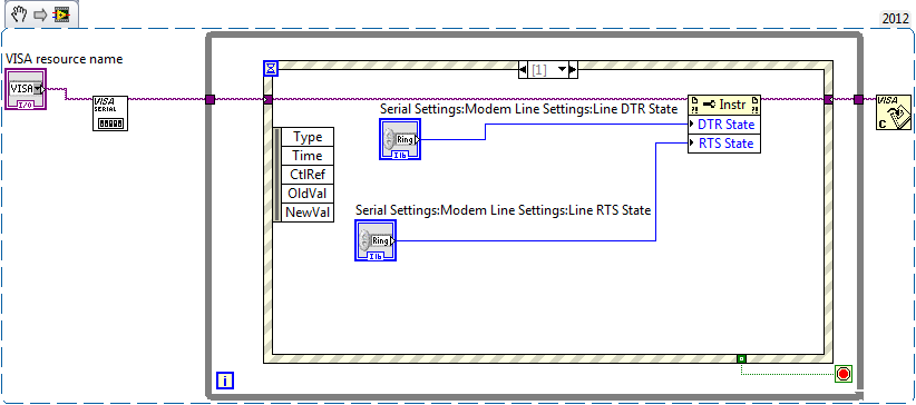
Now take a DMM and check the voltage levels on the line DTR and RTS of the COM port you

Should be 9 male pole D sub, careful of not to shortcut some ankles!
measure between pin 5 (GND) and PIN 4 (DTR) or 5 & 7 (RTS)
To light a LED, I would start with a LED of current low and a 10K resistor. If you have the LED's operating  replace by an optocoupler and resistance in order to limit your current below 5mA. (Say (12V_level - 1.8V_led) / 5mA-> ~ 2.2 kohms)
Tags: NI Hardware
Similar Questions
-
Implementation of multiple digital outputs with a box USB-6009
Hi all
I write the code to implement a USB-6009 multiple digital channels, digital outputs independent. I have configured the function of "DAQmx create Channel" to create 'a channel for each line', but I can't understand how to access and control these channels separately. Pointers would be greatly appreciated.
Thank you!
I thought about it. Never mind.
-
USB-6211 - digital output not supported?
Hi all
I can't use the USB6211 device port... I use daqmx with Delphi7 API functions.
First of all, I tried this:
DAQmxCreateTask('', @TaskDO);
DAQmxCreateDOChan (TaskDO, PChar('Dev1/port0'), ", DAQmx_Val_ChanForAllLines);
DAQmxWriteDigitalU8 (TaskDO, 1, 1, 1, DAQmx_Val_GroupByChannel, $FF, @written, nil);I had an error in the DAQmxWriteDigitalU8:-200012 (= digital output not supported). (???)
OK, I tried to disable autostart option based on DAQmxWriteDigitalU8 and insert a 'manual' start in the code:
DAQmxCreateTask('', @TaskDO);
DAQmxCreateDOChan (TaskDO, PChar('Dev1/port0'), ", DAQmx_Val_ChanForAllLines);
DAQmxStartTask (TaskDO);
DAQmxWriteDigitalU8 (TaskDO, 1, 0, 1, DAQmx_Val_GroupByChannel, $FF, @written, nil);
DAQmxStopTask (TaskDO);Now, I got the same error in DAQmxStartTask:-200012 (Digital Output not supported, once again). (?????)
I don't understand.. 'Digital output not supported "? USB-6211 has 4 lines! What is the problem?
I want to just turn on and off the lines from code...
-Cs George-
Well, finally I figured out...

Here is the solution:
DAQmxCreateTask('', @TaskDO);
DAQmxCreateDOChan (TaskDO, PChar('Dev1/port1'), ", DAQmx_Val_ChanForAllLines);
DAQmxWriteDigitalU8 (TaskDO, 1, @dummy, 1, DAQmx_Val_GroupByChannel, @bitmask, @written, nil);Digital output lines are on port1! Corrected parameter.
And the part of the interface of DAQmxWriteDigitalU8 had to be changed (in nidaqmx.pas).
I don't know why, but the AutoStart (dummy) parameter in the DAQmxWriteDigitalU8 function is ignored: function always starts task automatically, regardless of the value of autostart. But this isn't a problem for me.-Cs George-
-
digital output microsecond LED timer
Hey all,.
I'm doing a table of 10 LEDs in a row to form an analog timer to use to characterize the delay of the shutter on a digital SLR. We'll first stage shutter lag on the camera using a method different and well set the delay of the shutter for interior<1ms. i="" am="" trying="" to="" use="" labview="" alongside="" a="" ni="" usb="" 6251="" using="" an="" sc-2345="" for="" access="" to="" the="" digital="" outputs.="" im="" using="" a="" timed="" structure="" and="" a="" timed="" loop="" to="" ensure="" the="" timing="" between="" each="" led="" turning="" on="" corresponds="" to="" an="" actual="" time.="" however,="" i="" am="" not="" getting="" the="" results="" i="" thought="" i="" would.="" the="" timing="" does="" not="" seem="" to="" be="" what="" i="" thought="" it="" would="" be="" and="" i="" can="" not="" get="" the="" timed="" loop="" to="" work="" with="" all="" the="" channels="" at="" the="" desired="" frequency="" which="" would="" idealy="" be="" as="" high="" as="" possible.="" could="" someone="" take="" a="" look="" at="" my="" code="" and="" provide="" me="" with="" some="" insight="" where="" i="" may="" be="" getting="" issues?="" i="" apologize="" if="" i="" am="" overlooking="" important="" information="" that="" may="" be="" needed="" to="" help="" solve="">
~ Aaron
I have no DAQmx I can't be sure. I think that the 6251 has a maximum rate of 1 MHz in order to try to set the rate to 20 MHz should generate an error. For the purposes of test on the rate 1 Hz bit or less. Then you should be able to see the LEDs as turning on and off.
You may also need to set the number of samples to the size of the array. Referring to the size of the array fed to Scripture DAQmx, not the table on the front panel. With the number of samples set to 1, I would expect that he wrote that the first element of the array that is equal to zero. That does not produce a very interesting performance: he lets just all lights off the coast!
Lynn
-
Is it save to use the digital output as a digital input for another channel signal
Hi all
I know it's a stupid question, but I don't have another generator of signals by hand. What I want to know is, can I use the signal digital output of my USB-6001 as an input for the same signal device, but on other digital port? I wasn't directly because I don't want to burn the device...
Thank you
Done all the time. No problems.
-
take the digital output USB-6001 always high or low in c
Hi all
I am new to the NI DAQ interface. I have a USB-6001 and I am trying to use this device to control some flowchart in C. What I want to do is:
* set digital output lines with high and low intensity and change their status as needed (in C).
I tested the device NEITHER Max--> Test panels and found that the device is capable to do that. Then I try to do in C. I have checked hace examples and function I use is one called "DAQmxWriteDigitalU32". I have problem in the understanding of its input parameters. I tried something with my own knowledge, but it does not work as I expected. Here is a test I did:
data uInt32 = 1;
Int32 wrote;
TaskHandle taskHandle = 0;
DAQmxErrChk (DAQmxCreateTask("",&taskHandle));
DAQmxErrChk (DAQmxCreateDOChan (taskHandle, "Dev1/port0/line7", "", DAQmx_Val_ChanForAllLines));
DAQmxErrChk (DAQmxStartTask (taskHandle));
DAQmxErrChk (DAQmxWriteDigitalU32(taskHandle,1,1,10.0,DAQmx_Val_GroupByChannel,&data,&written,));taskHandle = 0;
DAQmxErrChk (DAQmxCreateTask("",&taskHandle));
DAQmxErrChk (DAQmxCreateDOChan (taskHandle, "Dev1/port0/$line0", "", DAQmx_Val_ChanForAllLines));
DAQmxErrChk (DAQmxStartTask (taskHandle));
DAQmxErrChk (DAQmxWriteDigitalU32(taskHandle,1,1,10.0,DAQmx_Val_GroupByChannel,&data,&written,));I just want to set ' Dev1/port0/line7' and ' Dev1/port0/$line0"at a high level, but only ' Dev1/port0/$line0' answer me. The second parameter of the DAQmxWriteDigitalU32 function is numSampsPerChan. If I replace (currently 1) with a higher value, such as 100, I see that "Dev1/port0/line7" sends a number of 1 output, then back to 0. So I guess that the problem is just that I understand not all parameters for the DAQmxWriteDigitalU32 function. Is someone can you please tell me how I can set up a line of digital output 1 or 0?
Thank you!
Hongkun
Hello
I finally find a way to do it! The feature works very well, and my problem was not set the data value to write correctly. It seems that if I want to write a 1 to the port0/line1, I put "data = 2 ^ 1" rather than "data = 1", because by default it is the second bit of the port.» Similarly, "data = 2 ^ 7 ' high level to port0/line7. I find that this setting is surprising when you want to control an individual line. It seems more reasonable when you control the whole port. In any case, is to solve the problem!
Thanks anyway!
Hongkun
-
NI USB-6501 digital output problem
Hello
I use DASYLab v.11 and I'm working on an interface with the NI USB-6501 where I'm putting a digital high on four ports.
With the module "NOR-DAQmx - digital input", I managed to read the digital inputs of the ' NI USB-6501 ".»
It's only the "NOR-DAQmx - digital output" I can't go to work.
Using 'NI MAX' of NOR I have easily can emmit my four LEDs in the way of my High/Low ports.
But not with DASYLab. When you use DASYLab tension on the ports remains unchanged.
Now, I have a switch module, generating 5/0, directly connected to the digital output module, which is assigned to my four output ports for my task.
I also tried with a module of relay between the two without success. I also tried to use 1.5 above instead of 5 without success.
I use the option 'Bus (0/5 supply) for the module "Digital output".
"NI Max", I configured the ports as "active drive.
Any suggestion of what I might be missing?
Thank you
Martin
Hmm, four ports, or four lines?
A port consists of eight lines. Each line can control an LED (ON / OFF ~ 0/5V).
If you have created a task to dig-out to control a port, 5V to this port sending sets all lines of this port to 'high '.
You need to 255 for each line one too high port (at the bit level: 128 + 64 + 32 + 16 + 8 + 4 + 2 + 1).<- eight="">
Or, you can create a dig out tasks to control four lines of a specific port.
Four lanes of the EEG DAQmx DigOut module.
Each of the channels of the modul will feed a single line of the task/device.
Four switches will then turn the lights, or turn off.
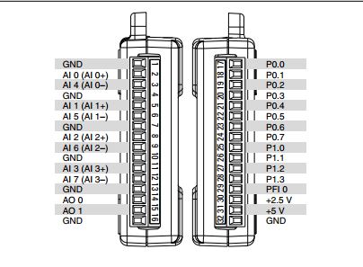
Make sure, that the 'bitposition' is the number of correct line (see picture).
-
Hello
I use the digital output to USB-6343.
Sometimes when I stop writing (clear the task) the rest at high output pin (I see it in the oscilloscope).
Is it possible to set that after earasing task output pin will always be low?
Thank you
Leonid
Thank you
-
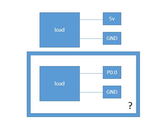
Digital I/o, the use of P0.0 for 5V output
On my data acquisition device (USB-6009), I already use the pinout + 5V and ground to control a sensor. I need to put another of the same sensor in my test set-up. Can I use the P0.0 as one + 5V out? and just ground the same pinout (32) of the load?
Why? You can wire the + 5 at several locations. If the detectors must be much more current, probably digital output will not source enough.
-
NI USB-6009 digital outputs are active when connected to a PC - I'm not that
I have a small problem:
All outputs digital NI USB-6009 module become active when the module is connected to a PC when no VI is running.
As soon as I start my VI, which controls the module, all the outputs are disabled (now inactive).
How can I achieve this, outputs are inactive if the module is connected to a PC with no program running?
johanneshoer wrote:
I have a small problem:
All outputs digital NI USB-6009 module become active when the module is connected to a PC when no VI is running.
As soon as I start my VI, which controls the module, all the outputs are disabled (now inactive).
How can I achieve this, outputs are inactive if the module is connected to a PC with no program running?
The USB-6008/6009 case has a pull-up internal (4.7 kOhm) resistance. This causes the outputs digital on the device to have a startup logic high State. t is not recommended to use some sort of resistance of menu drop-down. However, what you can do is add octal buffer like the 74HC541 stamp and a digital output to control the sorting of the 74hc541 state mode. Connect the OAS and CEO input signal. A Summit on the pins of the latter will be sorting the output of the buffer State. Therefore, no output signal will be present until you pull the stems of low control. The USB-6008/6009 case have a 5 volt output (200mA max), you can use the buffer.
-
Line of two-way digital for data asynchronous series using USB-6009?
Hello
I'm rather new to the LabVIEW environment, so I'm a little confused about this.
I have a signal conditioner chip (MAX1452), which I am trying to communicate with via the digital line.
The line is a bidirectional asynchronous, half-duplex serial.
I am currently trying to put up with a USB6009, and basically what I try to do is to write digital data (1 start bit, 8 bits, 1 stop bit, no parity, TTL logic) the smart and read the answer back. Is it possible to reconfigure a digital port on the USB-6009 case between an input and an output?
Or is there a better way for me to implement this?
Thank you.
Hi Gabriel,
It is not possible to simultaneously have a digital line on a product OR be out and a digital input. It is possible using the DAQmx controls, you can create a virtual channel that is a digital output, write data and disable the task. After that, you can try to create a new virtual channel which is a digital input, read the data and disable the task. However, the USB-6009 is a simple device, so it can not support this feature.
Hope this help to get you started,
-
Pull-up external USB-6009. digital output (open collector) allows onboard external + 2.5 V output?
Pull-up external USB-6009. digital output (open collector) allows onboard external + 2.5 V output?
Hello
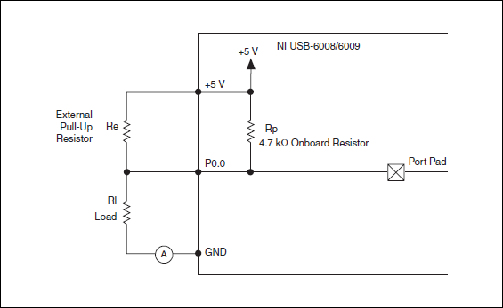
I want to config output digital USB-6009 to + 2.5 V above and 0 V digital output low. I know I can config USB-6009 digital output open collector with resistance to pull-up external, that can be applied with + 2.5 V power source.
My question is: can I use USB-6009 Board + 2.5 V output as the current source of resistance to pull-up? What resistance is a good number for the resistance to pull-up, if I can use this configuration?
Thank you much for the help.
Cathy
Hi Cathy,.
The digital USB 6008 front-end server looks like this:
So, there is actually an internal pullup to 5V 4.7 kOhm resistance when the device is configured to open collector.
If you want to display 0 to 2.5 V, I would look in a resistance of polarization of 4.7 kOhm between c and ground (according to the rest of your tour).
Best regards
-
USB-6008 to give the digital output
Hi all
I was wondering anyone at - it base an example of an exercise using USB 6008 to give a digital output of a VI in Labview.
I am very new to the use of the USB 6008 AND Assistant DAQ and so far I've had reading a temperature, next step is I want the USB-6008 to give a + 5v output when the temperature reaches a certain value, I built a Labview 2009 VI for the temperature reading, but now I'm stuck on this piece.
Any help is appreciated! or if there are examples of laboratory exercises that exist that I can perhaps draw.
Hi Marko
Please take a look at the link that has some interesting and intuitive video to use the USB-6008 housing and how to set up the device for several applications in LabVIEW below. Please take a look at the step by step videos and let me know how you go. They are under the tab '"virtual Demos.
-
Digital output of 6289 USB to the function generator
Hi ppl.

I have a DAQ USB-6289 card I use M series to interface with a programmable frequency AD 5932 generator (hope it's not breaking all the rules
 )
)In the datasheet of the http://www.analog.com/en/rfif-components/direct-digital-synthesis-dds/ad5932/products/product.html AD5932
It is the interface series (FSYNC, SCLK, SURLABASEDESDONNEESDUFABRICANTDUBALLAST).
I'm using LabVIEW to generate a digital output and help the Council 6289 to send the signal to the ad5932.
The problem is the following:
(1) I am an engineer in chemistry and new LabVIEW and electronics
(2) I don't understand how the digital signal and the FSYNC SCLK and SURLABASEDESDONNEESDUFABRICANTDUBALLAST are related... Sorry for the very basic question...

Hope that's not too much to ask, but if someone could suggest a tutorial or examples it would be EXTREMELLY appreciated...
Thanks for any input because I'm really stuck on this point.
See you soon
You need to find is the complete technical data on the A/D. Who will explain what each of these pins and the time served. It looks like an SPI interface. OR sell the 8451 for this programming. You can or perhaps are not able to use the 6289. I recommend a search of "SPI" to see if anyone has created a VI.
-
separation of two edges using a digital output
I am using a DAQ, PXI-6229 map and programming in c# .net.
I'm claiming a falling edge on PFI12 used as a digital output, and I need to measure the time between this edge and a second front on PFI8 used as a digital input. I have implemented the code using some examples I found. I don't know when to to argue the signal on PFI12 in order to be read at the right time. Playback must be put in place before the signal is asserted, but I do not know how to set it up it up properly.
Here is the code I have so far:
Public Sub MeasureAcquisitionTime()
{
DigitalSingleInputTask = new Task();
CIChannel counterSetup;
firstEdge = CITwoEdgeSeparationFirstEdge.Falling;
secondEdge = CITwoEdgeSeparationSecondEdge.Rising;
Double minTime = 10-3;
Double maxTime = 60F-3;
String auxCounterInput = "/" + CardName + ' / PFI12 ';
String gateCounterInput = "/" + CardName + ' / PFI8 ';
counterSetup = DigitalSingleInputTask.CIChannels.CreateTwoEdgeSeparationChannel)
CardName + ' / ctr1 ', 'counter',
minTime,
maxTime,
firstEdge, secondEdge, CITwoEdgeSeparationUnits.Seconds);
counterSetup.TwoEdgeSeparationFirstTerminal = auxCounterInput;
counterSetup.TwoEdgeSeparationSecondTerminal = gateCounterInput;
DigitalSingleInputTask.Control (TaskAction.Verify);
runningDigitalTask = DigitalSingleInputTask;
counterInReader = new CounterReader (DigitalSingleInputTask.Stream);
Double data = counterInReader.ReadSingleSampleDouble ();
}I'm glad to hear it.
paofthree wrote:
Is there a way to make a measure of separation of two edges on the analog inputs of the PXI-6229?
The only way would be to constantly acquire the analog input voltage and calculate the separation of the two edges in the software.
Best regards
Maybe you are looking for
-
new numbers does not open old documents
So when I have updated the computer my version of numbers updated. Now I have problem trying to open old documents & have to choose the version of numbers to use. Super irritating. Why have I not 2 versions of numbers instead of a updated version tha
-
Facebook does not have an option?
My facebook contacts are not appearing in the lists are available for synchronization, or to be added to my list of contacts xooms. Twitter contacts appear. Facebook contacts appear in my droid.
-
I have a laptop HP Windows 7. I tried to create a new folder in several locations photos and Documents, as well as on my Sandisk Flash Drive and it does not allow me too. I click the button new folder on top of the box of windows Explorer and nothi
-
picture of windows multipoint server premium edition 2011
Hello need urgent image of windows multipoint server premium edition 2011 I download the same support of https://www.microsoft.com/licensing/servicecenter/ download media is wrong (it's the image of windows server 2008 r2 edition) the name of the ima
-
solve the USB message is "unrecognized device".
has obtained the new cell phone... tried to load it on computer... would not load... got the support of the cellphone company and updates... can now cool phone however I get this message "one of the USB devices connected to computer has malfuntioned