digital output ARM nodes shipped
I MCB2300 and something more nodes digital output provided (LED 0-7). I have consulted for additional i/o elementary to the instructions here:
http://digital.NI.com/public.nsf/allkb/85DDB6218E7CEEBD8625756D007967CE
However, it only provides additional digital input nodes (even if the pins for these nodes are general-purpose digital input or output).
Is there a method to change these digital ouptut nodes?
Thank you
Hello
The generic MCB2300 target requires the following to access the outputs digital EIO:
- Add EIO of digital input of your project (as in your photo)
- Drop the EIO of digital input on your block diagram
- Click with the right button on the EIO node, and then select 'change to write '.
Tags: NI Products
Similar Questions
-
How can I more easily generate a pulse of digital output of finite length?
Hello
I need to open and close the two pneumatic valves using a TTL output (without load current or the output power) using a PCI-6280 or PCI-6601. The valves must open almost simultaneously and closing after different amounts of time elapsed (millisecond level timing, maybe 100 microseconds-level timing at worst). My current plan is as follows:
-Create a task with two digital outputs (type of waveform) and another task with a counter that generates a frequency set by the user (I know I can use the generator frequencies on one of these cards, but I would have preferred a counter - the best selection of frequencies).
-Wire the output of the counter at the entrance to clock two digital outputs.
-Output of the meter is digitally triggered by another digital channel which I use to control if the pulse goes out. Through its counter node, it is programmed to be redeclenchables.
-Two digital waveforms are drafted who have both consist of unique active high pulse (i.e. signals go ' down (for the amount of time user-defined) - low ".")
-These signals is written to their respective ports and their tasks have started, as is the task of the meter.
-Whenever the user wants to open taps, digital triggering is sent up and then back to low (this can be done with synchronization software, because it is not exactly when the fire valves). Whenever the user wants the valves open for a different period, different digital waveforms are generated and written in the buffers of the digital output channels.
My problem is that it looks like a lot of effort for me to go and I wonder if there is a much simpler solution, that I don't know everything. You can program a computer to produce a pulse of finite length? Is there a faster way to program a digital output for that channel?
Thanks to anyone who responds to their help.
It is certainly instructive. Thank you.
The thing is, I have only six total counters to work with and I have a lot of time to do things. To use these solutions, I would need to use 4 or 6 account counters required to my needs.also that I would need to synchronize their departures.
Overall, I stick to my method for now - less system resources and synchronization can be don by using the same meter of finished output clock and not to use a trigger to all.
Once again, thank you for your help so far.
-
Hello
Here's my problem: I want to generate digital samples (10-bit) whenever I get a digital external trigger.
This should be easy since I could still do it with the express DAQmxVI.
But the switch can go up to 120 Hz and 16Hz, the generation is not fast enough. It seems like the writing of digital output configuration takes too much time on each loop.
I don't know I'm missing something... can anyone help me on this or point me to some documents that I could use?
Which would be very appreciated.
Thank you
R
PS: I use a NI6351 USB card to get the external trigger on PFI0 and write the numeric data I want to send.
I found the answer and share the link here:
https://decibel.NI.com/content/docs/doc-25189
Thanks to Nathan-P!
Basically my USB6351 NOR is not redeclenchables, otherwise, you just add a property trigger Daqmx with redeclenchables true node. But with this thing, it works great!
R
-
audio output: optical digital output port (no sound!) macbook pro retina 15 mid 2015
My new recently Mbpr 15 inch has suddenly lost its sound, I went through the process of the toothpick etc but nothing. It worked perfectly fine earlier today, but I put in a mini jack into the headphone port and after to achieve 30 minutes later and taking the cable to THE that I had not his, then I had the red light coming out of the helmet but now its does not come in red and in the sound settings in system preferences its impasse on "optical digital output Port.
I now have to wait a week to wait until I can get seen at my apple store closet, I coming projects upward and in the middle of deadline and really using this Mbp to work, I literally only had a TI surly less than two months, I shouldn't have any problems. So if anyone knows anything I would appreciate it a lot! I need help to get this resolution as soon as possible! the last post I saw this was in 2006-2012 no new thread on this recently!
Thank you!
Jasonwaterz wrote:
I then had the red light coming out of the helmet but now its does not come in red and in the sound settings in system preferences its impasse on "optical digital output Port.
Try resetting the NVRAM/PRAM http://support.apple.com/kb/ht1379 memory
-
Realtek integrated sound card is stuck in digital output
I can't get this thing off the digital output mode. Now I have no sound because all analog ports do not work. Telling me that nothing is plugged. I can't reset the analog speaker because it is grayed in Vista. This problem seems to be very common with computers using Realtek and Vista, just do a google search and see for yourself.
I have a feeling it has software problem between Vista and Realtek. But I really think Realtek is just terrible to began with and should not be put in any period of the computer. If I can't get this thing works here tomorrow I will get a good real map.
Message edited by hn333 on 09/04/2009 21:02I had very similar problems and finally managed to solve it.
Something seems to be borked with drivers realtek about automatic jack detection.
After attempting to use the method described here (easier if you can) http://freeweelee.wordpress.com/2008/12/09/vista-and-realtek-front-panel-audio-not-working-solution/, I discovered that I was completely unable to cut jack detection in audio Manager Realtek (no folder icon).
For those of you who (like me) have no icon file, I managed to find another way to disable the detection of jack.
Using the registry editor, find all instances of ForceDisableJD and change the value from 00 to FF.
After making sure that I got all of them, I was able to reboot and everything works fine now.
-
No digital output on a Satellite P200
I just bought a Satellite P200 and am trying to put it to the test. Today I tried recording on a digital audio recorder (Edirol R-4) connected to the output digital output jack but can get no signal. I can get a signal from the analog headphone jack.
I have no problem with digital recording of my desktop PC which has an installed Sound Blaster card so it doesn't seem to be an incompatibility or a problem with the connecting cable.
I tried to set the default output to digital mode in the setup of REALtek but no difference.
Any suggestions gratefully received.
David
Anyone else had this problem?
David
-
Synchronization of analog and digital output with the external sample clock
Hello
First of all sorry for my English, I will try to explain what I want to do.
I want my PCIe-6321 to send two custom signals (modification sawtooths) on a mirror controller. I would also like to generate output with my card at the beginning of each tooth of saw. Everything must be synchronized with an external k-clock signal of 100 kHz. The idea is that whenever the PCI receives a trigger to external clock, it sends two analog output voltages and when he received 1024 clock ticks it will also send a pic of triggering TTL. What I do is first prepare the map and after that in a loop sending and modifing the output values of the two signals and at the same time send a digital signal Boolean in each arch, so when's done it 1024 iterations of the loop I send an event to the digital port. Attached you can see.
The problem is that I don't know how to synchronize both. Can I use the sample clock just to the analog output? I can use sample for the two outputs clock, or do I need to use the output of the meter? If don't know how to use it here.
If I do nothing else bad/wrong, I would be grateful for feedback.
Thanks in advance,
PabloI don't know how but I find the solution. I'm generating more than a positive value (as I was triggered maybe very fast the oscilloscope has been absent there). If I put the sample clock of digital output to use the sampling/ao/Dev1 clock that it doesn't, but if I put to use the same source as the OD (terminal where my external clock is connected), but the trigger to start the DO to be Dev1/ao/StartTrigger this works. I don't really know why, but it does.
Thank you for your patience and your help. I put here the final code.
-
redeclenchables strange behavior digital output
I created a redeclenchables digital dashboard task (finished) digital output as follows: (in DAQmx C)
DAQmxCreateTask("",&_taskHandle);
DAQmxCreateDOChan(_taskHandle,"/Dev2/port0/line6","",DAQmx_Val_ChanPerLine);
DAQmxCfgSampClkTiming (_taskHandle, "" / Dev2/Ctr0InternalOutput ", _clockRate, DAQmx_Val_Rising, DAQmx_Val_FiniteSamps, static_cast (_sampleCount)");
DAQmxCfgOutputBuffer (_taskHandle, static_cast (_sampleCount));
DAQmxCfgDigEdgeStartTrig (_taskHandle, "/ Dev2/PFI4", DAQmx_Val_Rising ");
DAQmxSetStartTrigRetriggerable (_taskHandle, true);
DAQmxWriteDigitalLines (_taskHandle, static_cast(_sampleCount), FALSE,-1, DAQmx_Val_GroupByChannel, _pDigital, NULL, NULL);
DAQmxStartTask (_taskHandle);sample clock:
DAQmxCreateTask ("", & _taskHandleCO);
DAQmxCreateCOPulseChanFreq (_taskHandleCO, "/ Dev2/ctr0","", DAQmx_Val_Hz, DAQmx_Val_Low, 0,0, _clockRate, 0.5 "");
DAQmxCfgImplicitTiming (_taskHandleCO, DAQmx_Val_ContSamps, _numSamples);
DAQmxStartTask (_taskHandleCO);When I run the task without redeclenchables parameter, it output a correct signal. However, if I run with redeclenchables it out almost exactly 2 times faster than normal. For example, a pulse whose width of 10 ms became 5 ms and repeats again to be 2 pulses of 5 ms. This is repeatable, no matter how much or how fast triggers provided.
My card is PCIe-6363. I do not know what causes this strange behavior, and I hope someone can help on this.
Thank you.
It disappears after reset configuration. Might be interesting for future reviews.
-
Is it save to use the digital output as a digital input for another channel signal
Hi all
I know it's a stupid question, but I don't have another generator of signals by hand. What I want to know is, can I use the signal digital output of my USB-6001 as an input for the same signal device, but on other digital port? I wasn't directly because I don't want to burn the device...
Thank you
Done all the time. No problems.
-
take the digital output USB-6001 always high or low in c
Hi all
I am new to the NI DAQ interface. I have a USB-6001 and I am trying to use this device to control some flowchart in C. What I want to do is:
* set digital output lines with high and low intensity and change their status as needed (in C).
I tested the device NEITHER Max--> Test panels and found that the device is capable to do that. Then I try to do in C. I have checked hace examples and function I use is one called "DAQmxWriteDigitalU32". I have problem in the understanding of its input parameters. I tried something with my own knowledge, but it does not work as I expected. Here is a test I did:
data uInt32 = 1;
Int32 wrote;
TaskHandle taskHandle = 0;
DAQmxErrChk (DAQmxCreateTask("",&taskHandle));
DAQmxErrChk (DAQmxCreateDOChan (taskHandle, "Dev1/port0/line7", "", DAQmx_Val_ChanForAllLines));
DAQmxErrChk (DAQmxStartTask (taskHandle));
DAQmxErrChk (DAQmxWriteDigitalU32(taskHandle,1,1,10.0,DAQmx_Val_GroupByChannel,&data,&written,));taskHandle = 0;
DAQmxErrChk (DAQmxCreateTask("",&taskHandle));
DAQmxErrChk (DAQmxCreateDOChan (taskHandle, "Dev1/port0/$line0", "", DAQmx_Val_ChanForAllLines));
DAQmxErrChk (DAQmxStartTask (taskHandle));
DAQmxErrChk (DAQmxWriteDigitalU32(taskHandle,1,1,10.0,DAQmx_Val_GroupByChannel,&data,&written,));I just want to set ' Dev1/port0/line7' and ' Dev1/port0/$line0"at a high level, but only ' Dev1/port0/$line0' answer me. The second parameter of the DAQmxWriteDigitalU32 function is numSampsPerChan. If I replace (currently 1) with a higher value, such as 100, I see that "Dev1/port0/line7" sends a number of 1 output, then back to 0. So I guess that the problem is just that I understand not all parameters for the DAQmxWriteDigitalU32 function. Is someone can you please tell me how I can set up a line of digital output 1 or 0?
Thank you!
Hongkun
Hello
I finally find a way to do it! The feature works very well, and my problem was not set the data value to write correctly. It seems that if I want to write a 1 to the port0/line1, I put "data = 2 ^ 1" rather than "data = 1", because by default it is the second bit of the port.» Similarly, "data = 2 ^ 7 ' high level to port0/line7. I find that this setting is surprising when you want to control an individual line. It seems more reasonable when you control the whole port. In any case, is to solve the problem!
Thanks anyway!
Hongkun
-
NI USB-6501 digital output problem
Hello
I use DASYLab v.11 and I'm working on an interface with the NI USB-6501 where I'm putting a digital high on four ports.
With the module "NOR-DAQmx - digital input", I managed to read the digital inputs of the ' NI USB-6501 ".»
It's only the "NOR-DAQmx - digital output" I can't go to work.
Using 'NI MAX' of NOR I have easily can emmit my four LEDs in the way of my High/Low ports.
But not with DASYLab. When you use DASYLab tension on the ports remains unchanged.
Now, I have a switch module, generating 5/0, directly connected to the digital output module, which is assigned to my four output ports for my task.
I also tried with a module of relay between the two without success. I also tried to use 1.5 above instead of 5 without success.
I use the option 'Bus (0/5 supply) for the module "Digital output".
"NI Max", I configured the ports as "active drive.
Any suggestion of what I might be missing?
Thank you
Martin
Hmm, four ports, or four lines?
A port consists of eight lines. Each line can control an LED (ON / OFF ~ 0/5V).
If you have created a task to dig-out to control a port, 5V to this port sending sets all lines of this port to 'high '.
You need to 255 for each line one too high port (at the bit level: 128 + 64 + 32 + 16 + 8 + 4 + 2 + 1).<- eight="">
Or, you can create a dig out tasks to control four lines of a specific port.
Four lanes of the EEG DAQmx DigOut module.
Each of the channels of the modul will feed a single line of the task/device.
Four switches will then turn the lights, or turn off.
Make sure, that the 'bitposition' is the number of correct line (see picture).
-
Hello
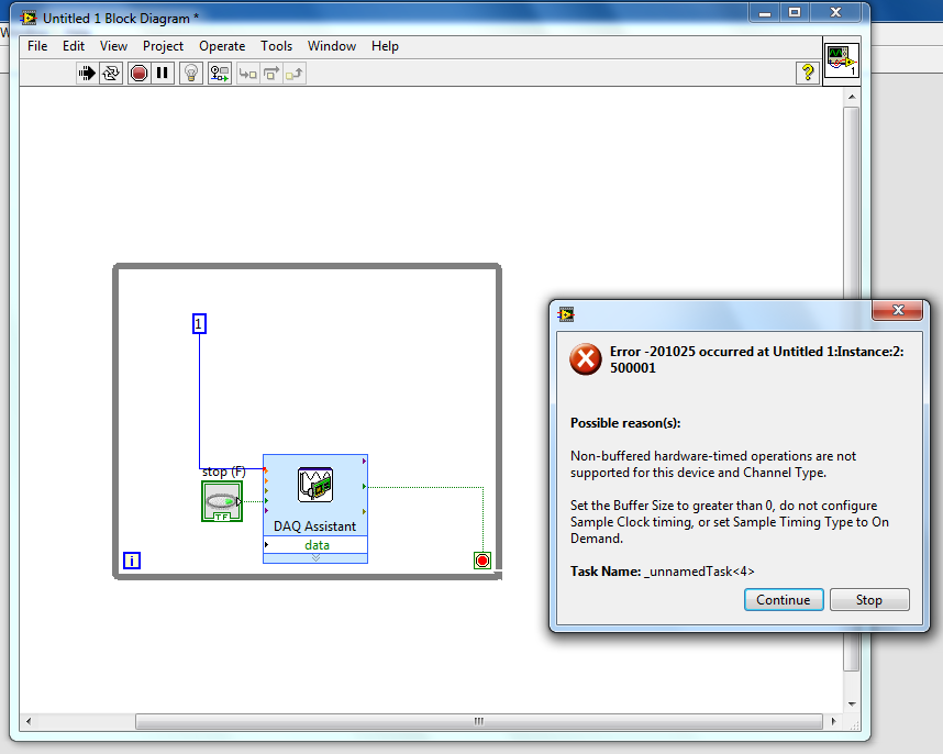
I'm playing with NI 9474 to learn how the outputs digital work with labview. However, I can't even the basic element down. I have a 9v battery connected to the unit and an element of resistance hung on one of the terminals of the device output. So, I just try to get labview to produce a digital output.
However, I get an error when I try to run the labview program. I tried to search my error on the knowledge base, but has been unable to find it. So if someone could help me understand how digital material output works with labview, it would be awesome!
I have attached my diagram!
Thank you
It's pretty basic. If you make an entry, you must specify the values to be written. For digital, values are true/false or 1/0.
-
CV 1457RT and VBAI: Double digital output
I have a problem with the CVS 1457RT and the VBAI.
I configured two steps with the VBAI for the CVS.
The first step: I've read about the digital input which should trigger my second step.
the second step: I acquire an image (with an ACE of the Basler) and then I measured 8 distances and count 2 edges. After this, I generate a pulse on the digital output once.
After that I did a VI in LabVIEW that measures the time between the IO.
In this VI and on the module which is connected to the digital output, I see that the putput pulses twice but only a few times.
I guess you get noise on your digital input and trigger twice, so that it works the inspection twice, giving you two pulse output.
You can implement a digital filter, where the value that comes out of the filter does not change until entry remained at the same value for the N samples.
Bruce
-
separation of two edges using a digital output
I am using a DAQ, PXI-6229 map and programming in c# .net.
I'm claiming a falling edge on PFI12 used as a digital output, and I need to measure the time between this edge and a second front on PFI8 used as a digital input. I have implemented the code using some examples I found. I don't know when to to argue the signal on PFI12 in order to be read at the right time. Playback must be put in place before the signal is asserted, but I do not know how to set it up it up properly.
Here is the code I have so far:
Public Sub MeasureAcquisitionTime()
{
DigitalSingleInputTask = new Task();
CIChannel counterSetup;
firstEdge = CITwoEdgeSeparationFirstEdge.Falling;
secondEdge = CITwoEdgeSeparationSecondEdge.Rising;
Double minTime = 10-3;
Double maxTime = 60F-3;
String auxCounterInput = "/" + CardName + ' / PFI12 ';
String gateCounterInput = "/" + CardName + ' / PFI8 ';
counterSetup = DigitalSingleInputTask.CIChannels.CreateTwoEdgeSeparationChannel)
CardName + ' / ctr1 ', 'counter',
minTime,
maxTime,
firstEdge, secondEdge, CITwoEdgeSeparationUnits.Seconds);
counterSetup.TwoEdgeSeparationFirstTerminal = auxCounterInput;
counterSetup.TwoEdgeSeparationSecondTerminal = gateCounterInput;
DigitalSingleInputTask.Control (TaskAction.Verify);
runningDigitalTask = DigitalSingleInputTask;
counterInReader = new CounterReader (DigitalSingleInputTask.Stream);
Double data = counterInReader.ReadSingleSampleDouble ();
}I'm glad to hear it.
paofthree wrote:
Is there a way to make a measure of separation of two edges on the analog inputs of the PXI-6229?
The only way would be to constantly acquire the analog input voltage and calculate the separation of the two edges in the software.
Best regards
-
Hello
I use the digital output to USB-6343.
Sometimes when I stop writing (clear the task) the rest at high output pin (I see it in the oscilloscope).
Is it possible to set that after earasing task output pin will always be low?
Thank you
Leonid
Thank you
Maybe you are looking for
-
This happened also with your support site!
-
Is a Macbook pro of the retina display 8 gb good for video editing?
I want to buy the Macbook with 8 GB memory pro retina display, speed 2.7 gigahertz and 256 GB Flash storage. I want to work with imovie and final cut pro, it would make for me. What should I expect?
-
Malfunction of the Structure of the event?
Apparently, an event structure keeps listening events even if the structure has to be inactive as it is located in the inactive case of a box structure. See the attached example. Explanations, comments or whatever? Is this yet another bug or a signif
-
Hello! HP ENVY Sleekbook 6 PC (Windows 8) I have reset to factory settings. Is it possible to recover data that has been delivered to? (Documents)Thank you!
-
print all-in-one Deskjet 3522nd: won't print black
I have a deskjet printer 3522 who don't print black ink. It becomes more low - where will the ink? I changed the cartridges which were all new HP ink. I cleaned the pinhead of many times. I tried a difficult start. Ideas - other than throw it out th