digital output microsecond LED timer
Hey all,.
I'm doing a table of 10 LEDs in a row to form an analog timer to use to characterize the delay of the shutter on a digital SLR. We'll first stage shutter lag on the camera using a method different and well set the delay of the shutter for interior<1ms. i="" am="" trying="" to="" use="" labview="" alongside="" a="" ni="" usb="" 6251="" using="" an="" sc-2345="" for="" access="" to="" the="" digital="" outputs.="" im="" using="" a="" timed="" structure="" and="" a="" timed="" loop="" to="" ensure="" the="" timing="" between="" each="" led="" turning="" on="" corresponds="" to="" an="" actual="" time.="" however,="" i="" am="" not="" getting="" the="" results="" i="" thought="" i="" would.="" the="" timing="" does="" not="" seem="" to="" be="" what="" i="" thought="" it="" would="" be="" and="" i="" can="" not="" get="" the="" timed="" loop="" to="" work="" with="" all="" the="" channels="" at="" the="" desired="" frequency="" which="" would="" idealy="" be="" as="" high="" as="" possible.="" could="" someone="" take="" a="" look="" at="" my="" code="" and="" provide="" me="" with="" some="" insight="" where="" i="" may="" be="" getting="" issues?="" i="" apologize="" if="" i="" am="" overlooking="" important="" information="" that="" may="" be="" needed="" to="" help="" solve="">
~ Aaron
I have no DAQmx I can't be sure. I think that the 6251 has a maximum rate of 1 MHz in order to try to set the rate to 20 MHz should generate an error. For the purposes of test on the rate 1 Hz bit or less. Then you should be able to see the LEDs as turning on and off.
You may also need to set the number of samples to the size of the array. Referring to the size of the array fed to Scripture DAQmx, not the table on the front panel. With the number of samples set to 1, I would expect that he wrote that the first element of the array that is equal to zero. That does not produce a very interesting performance: he lets just all lights off the coast!
Lynn
Tags: NI Software
Similar Questions
-
digital output ARM nodes shipped
I MCB2300 and something more nodes digital output provided (LED 0-7). I have consulted for additional i/o elementary to the instructions here:
http://digital.NI.com/public.nsf/allkb/85DDB6218E7CEEBD8625756D007967CE
However, it only provides additional digital input nodes (even if the pins for these nodes are general-purpose digital input or output).
Is there a method to change these digital ouptut nodes?
Thank you
Hello
The generic MCB2300 target requires the following to access the outputs digital EIO:
- Add EIO of digital input of your project (as in your photo)
- Drop the EIO of digital input on your block diagram
- Click with the right button on the EIO node, and then select 'change to write '.
-
Speakers and digital output device problem
So yesterday, I installed a new video card. A Nvidia Geforce GT220. After installing it I noticed that my speakers were not working. The default program I used was Realtek High Definition Audio. I checked in Device Manager and noticed that the Realtek HD Audio Driver/program had a small yellow triangle with an exclamation point and that there are 4 new options named Nvidia High Definition Audio. Whenever I tried to run Realtek it says that the program has been installed, but may not be installed correctly. He said it was a Code 10. So finally, I deleted Realtek but the Nvidia High Definition audio drivers did not work. So, I deleted the drivers from Nvidia High Definition audio and tried to reinstall Realtek. My computer says that I installed it but there is no program to access my different options.
Now when I check the sound folder, during playback it says peripheral digital output (HDMI) 4 times.
Although the sound does not work.
Im just trying to run her on my Logitech X 540 speakers. When I plug the speakers that they appear not yet as an option in the sound folder.I don't really know what I can do to make it work.
I have a HP with Windows Vista 32 bit a1730n.
Hello TheInnocentMan,
You can try the methods below to resolve this issue.
Method 1:
I suggest you follow the link below and run the fix. This will automatically diagnose and repair problems with sound and audio on your computer. Here is a link you can follow:
http://Windows.Microsoft.com/en-us/Windows-Vista/tips-for-fixing-common-sound-problems
Method 2:
Check whether the default playback device is activated and the default value. It must essentially be your Realtek audio device.
a. open peripheral Audio and sound themes by clicking the Start button, click Control Panel, hardware and sound, and then clicking sound.
b. click on the playback tab, click speakers and then click Properties.
c. Select the device as the default device.
Thank you
Irfan H, Engineer Support Microsoft Answers. Visit ourMicrosoft answers feedback Forum and let us know what you think. -
Digital output with timer (Simulation)
Hello everyone, I just found out how LabVIEW program a week ago. I try to do a simulation of digital output by LabVIEW (my attachment). In this simulation, I have a slider as an input (0-10 V), two digital controls (upper limit and lower limit), a waveform graph draw these 3 evaluates and two Boolean LED (P0.0 and P0.1) as indicator. In this simulation, you can fill any number (between 0 and 10) in numerical order as a limit for your entry cursor. If the entrance of a cursor exceeds these upper and lower limit, then the Boolean LED lights, P0.0 so exceeds the upper limit, and if P0.1 exceeds the lower limit. The problem is that I do not know how the timer for those Boolean LED. As an example:
(1) make an entry of cursor,
(2) if entry (1) exceeds the upper limit, P0.0 lights for 5 seconds, then turn to during 10 second.
(3) if only 10 seconds, you change the entry back to normal (between high and low limit) then P0.0 will stay turn of until the cursor entry exceeds the upper limit again,.
(4) If, in this second 10 you has not changed the entry (the stay exceeds the upper limit) then P0.0 repeats the process (2) until you the entrance to cursor back to normal.
(Same process for entries exceed the lower limit).
Can you help me do this timer? Thank you

Concerning
Juventom
Hello
If you don t mind I would just give you some advise to your code. To determine the data stream you can also use only the error wire connected to the loop. So Don t you really need, it's beter not not to use variables. For your solution, you can use something similar to what I tried for the upper limit in your program. It is added as an image.
Hope it helps
-
Hallo,
I use the following system:
- OR PXI-1044 with controller NI PXI-8109
- OR PXI-2564 switch module to turn on the monitor of my test device
- Data acquisition multifunction NI PXI-6259 to measure the signal that responded to the questionnaire jump
The two cards are the same - PXI trigger bus. For both, PXI-2564 and PXI-6259 I use DAQmx to set the reading and writing of the channels.
Now, I want to measure the time between the digital output, my unit turns and the analog input, which measures the response of my system.
I can't do work by myself, please help me!
I thank Ludwig.
Hi Ludwig,.
If you can't give us any VI we have difficulties with to help you.
Because I Donat knowledge how your program is mounted it is not easy to know where you should enter signals.
Here's a question similar to yours:
http://forums.NI.com/T5/LabVIEW/best-way-to-measure-time/TD-p/178704
and 2 external links:
http://www.ehow.com/how_8698983_measure-time-LabVIEW.html
http://objectmix.com/LabVIEW/385152-how-can-i-use-LabVIEW-measure-time-between-analog-pulses.html
-
Fortunately the cRIO merger two time real screws: analog and digital output
Howdy,
I need help with a cRIO code. The purpose of the code is to acquire an analog input from the NI 9234 c series module and be able to send a "signal of pulse" digital camera (first low for some time, t1, then high for some time, t2) from a NI9401. Separately, I wrote the code to perform both tasks. However, when I add the code of RT digital output pulse pulses to analog input RT code, the DMA FIFO overflows because of the way that my digital pulse output code works. Currently, there are two reasons which overflows of the FIFO:
- The digital output code is pending for a while loop (pending "Send Pulse" become a true), the loop I can't empty the buffer FIFO
- The FIFO is not enough, quickly emptied depending on how long the pulse (t1 and t2) times are. The way I keep the pin high or low for a defined period of time is by issuing a sleep command, which blocks the loop I empty the FIFO. (Is there a "best" way to sleep?)
I have attached photos of my codes FPGA and RT. Please give me a suggestion on how to marry my two loops of RT for the use of happy resources! Thank you.
I found a quick way to solve this problem. I moved the timing of the Digital pulse on the FPGA. So whenever I have a Boolean value, the FPGA generates a waveform with the settings I put (a pulse in my case). This works because the FPGA loops run in parallel, I think. That's why, when I run a pending order in the loop of FPGA digital output, it does not prevent the FPGA of analog input loop to run. I have attached a picture of the code.
-
How can I more easily generate a pulse of digital output of finite length?
Hello
I need to open and close the two pneumatic valves using a TTL output (without load current or the output power) using a PCI-6280 or PCI-6601. The valves must open almost simultaneously and closing after different amounts of time elapsed (millisecond level timing, maybe 100 microseconds-level timing at worst). My current plan is as follows:
-Create a task with two digital outputs (type of waveform) and another task with a counter that generates a frequency set by the user (I know I can use the generator frequencies on one of these cards, but I would have preferred a counter - the best selection of frequencies).
-Wire the output of the counter at the entrance to clock two digital outputs.
-Output of the meter is digitally triggered by another digital channel which I use to control if the pulse goes out. Through its counter node, it is programmed to be redeclenchables.
-Two digital waveforms are drafted who have both consist of unique active high pulse (i.e. signals go ' down (for the amount of time user-defined) - low ".")
-These signals is written to their respective ports and their tasks have started, as is the task of the meter.
-Whenever the user wants to open taps, digital triggering is sent up and then back to low (this can be done with synchronization software, because it is not exactly when the fire valves). Whenever the user wants the valves open for a different period, different digital waveforms are generated and written in the buffers of the digital output channels.
My problem is that it looks like a lot of effort for me to go and I wonder if there is a much simpler solution, that I don't know everything. You can program a computer to produce a pulse of finite length? Is there a faster way to program a digital output for that channel?
Thanks to anyone who responds to their help.
It is certainly instructive. Thank you.
The thing is, I have only six total counters to work with and I have a lot of time to do things. To use these solutions, I would need to use 4 or 6 account counters required to my needs.also that I would need to synchronize their departures.
Overall, I stick to my method for now - less system resources and synchronization can be don by using the same meter of finished output clock and not to use a trigger to all.
Once again, thank you for your help so far.
-
How to measure the digital output of the linear actuator on USB-6009?
Hello
I am a new user of Labview and need help to measure a digital input signal.
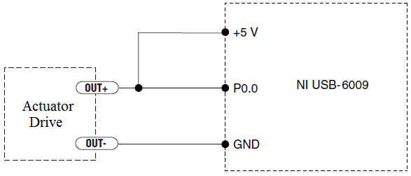
I have an actuator Bimba Original line electric with a motor continuous integrated with encoder, drive and the controller. The drive has a programmable digital output that I put as a tachometer output that emits pulses of square wave 100 per turn of the engine. I put the engine to make a total of 56 rev in 22 dry. I want to measure the speed of motor rotation labview real-time and synchronize it with a few other analog input signals. I wired the actuator for the USB-6009 case as shown below.
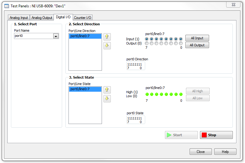
I opened the test i/o digital USB-6009 Panel and fix all the lines of port 0 as inputs. However, when I click on start and run the actuator, p0.0 led flashes, as indicated below.
Shouldn't the led blink in response to revolutions of engines?
I want basically to collect the drive pulse signals and convert them in rpm on labview.
ahsan2 wrote:
I have it wired correctly?
It would help if you do not attach the HIGH signal. Remove the + 5V in the circuit.
-
Control the Boolean commands and generate a corresponding digital output
Hi all
I'm working on a project of activation of the electrode, here, I thought that how could I order an electrode in a time and generate a digital output of it accordingly. I want to replace it with each electrode with a LED on the front panel and generate a numerical value to each LED on the block diagram.
If it can be divided into two parts
1 control the Boolean outputs
Here, my goal is that if I have 5 leds that are used as a Boolean control, must be ordered so that only one of them lights up at the same time and the rest goes off.
I mean for example if #3 was turned on and that the user pressed the #3 #2 should be turned off and only #2 lights.
2. generate the corresponding numerical value
Depending on the position of the LEDs I want to generate a corresponding numerical value, as previously released 3 coming and exit 2 then comes when the second LED illuminates.I ask all participants to this group to help me with this.
Concerning
Why don't you use the radio button control? You can replace the boxes if you want the buttons.
-
Synchronization of analog and digital output with the external sample clock
Hello
First of all sorry for my English, I will try to explain what I want to do.
I want my PCIe-6321 to send two custom signals (modification sawtooths) on a mirror controller. I would also like to generate output with my card at the beginning of each tooth of saw. Everything must be synchronized with an external k-clock signal of 100 kHz. The idea is that whenever the PCI receives a trigger to external clock, it sends two analog output voltages and when he received 1024 clock ticks it will also send a pic of triggering TTL. What I do is first prepare the map and after that in a loop sending and modifing the output values of the two signals and at the same time send a digital signal Boolean in each arch, so when's done it 1024 iterations of the loop I send an event to the digital port. Attached you can see.
The problem is that I don't know how to synchronize both. Can I use the sample clock just to the analog output? I can use sample for the two outputs clock, or do I need to use the output of the meter? If don't know how to use it here.
If I do nothing else bad/wrong, I would be grateful for feedback.
Thanks in advance,
PabloI don't know how but I find the solution. I'm generating more than a positive value (as I was triggered maybe very fast the oscilloscope has been absent there). If I put the sample clock of digital output to use the sampling/ao/Dev1 clock that it doesn't, but if I put to use the same source as the OD (terminal where my external clock is connected), but the trigger to start the DO to be Dev1/ao/StartTrigger this works. I don't really know why, but it does.
Thank you for your patience and your help. I put here the final code.
-
redeclenchables strange behavior digital output
I created a redeclenchables digital dashboard task (finished) digital output as follows: (in DAQmx C)
DAQmxCreateTask("",&_taskHandle);
DAQmxCreateDOChan(_taskHandle,"/Dev2/port0/line6","",DAQmx_Val_ChanPerLine);
DAQmxCfgSampClkTiming (_taskHandle, "" / Dev2/Ctr0InternalOutput ", _clockRate, DAQmx_Val_Rising, DAQmx_Val_FiniteSamps, static_cast (_sampleCount)");
DAQmxCfgOutputBuffer (_taskHandle, static_cast (_sampleCount));
DAQmxCfgDigEdgeStartTrig (_taskHandle, "/ Dev2/PFI4", DAQmx_Val_Rising ");
DAQmxSetStartTrigRetriggerable (_taskHandle, true);
DAQmxWriteDigitalLines (_taskHandle, static_cast(_sampleCount), FALSE,-1, DAQmx_Val_GroupByChannel, _pDigital, NULL, NULL);
DAQmxStartTask (_taskHandle);sample clock:
DAQmxCreateTask ("", & _taskHandleCO);
DAQmxCreateCOPulseChanFreq (_taskHandleCO, "/ Dev2/ctr0","", DAQmx_Val_Hz, DAQmx_Val_Low, 0,0, _clockRate, 0.5 "");
DAQmxCfgImplicitTiming (_taskHandleCO, DAQmx_Val_ContSamps, _numSamples);
DAQmxStartTask (_taskHandleCO);When I run the task without redeclenchables parameter, it output a correct signal. However, if I run with redeclenchables it out almost exactly 2 times faster than normal. For example, a pulse whose width of 10 ms became 5 ms and repeats again to be 2 pulses of 5 ms. This is repeatable, no matter how much or how fast triggers provided.
My card is PCIe-6363. I do not know what causes this strange behavior, and I hope someone can help on this.
Thank you.
It disappears after reset configuration. Might be interesting for future reviews.
-
Is it save to use the digital output as a digital input for another channel signal
Hi all
I know it's a stupid question, but I don't have another generator of signals by hand. What I want to know is, can I use the signal digital output of my USB-6001 as an input for the same signal device, but on other digital port? I wasn't directly because I don't want to burn the device...
Thank you
Done all the time. No problems.
-
NI USB-6501 digital output problem
Hello
I use DASYLab v.11 and I'm working on an interface with the NI USB-6501 where I'm putting a digital high on four ports.
With the module "NOR-DAQmx - digital input", I managed to read the digital inputs of the ' NI USB-6501 ".»
It's only the "NOR-DAQmx - digital output" I can't go to work.
Using 'NI MAX' of NOR I have easily can emmit my four LEDs in the way of my High/Low ports.
But not with DASYLab. When you use DASYLab tension on the ports remains unchanged.
Now, I have a switch module, generating 5/0, directly connected to the digital output module, which is assigned to my four output ports for my task.
I also tried with a module of relay between the two without success. I also tried to use 1.5 above instead of 5 without success.
I use the option 'Bus (0/5 supply) for the module "Digital output".
"NI Max", I configured the ports as "active drive.
Any suggestion of what I might be missing?
Thank you
Martin
Hmm, four ports, or four lines?
A port consists of eight lines. Each line can control an LED (ON / OFF ~ 0/5V).
If you have created a task to dig-out to control a port, 5V to this port sending sets all lines of this port to 'high '.
You need to 255 for each line one too high port (at the bit level: 128 + 64 + 32 + 16 + 8 + 4 + 2 + 1).<- eight="">
Or, you can create a dig out tasks to control four lines of a specific port.
Four lanes of the EEG DAQmx DigOut module.
Each of the channels of the modul will feed a single line of the task/device.
Four switches will then turn the lights, or turn off.
Make sure, that the 'bitposition' is the number of correct line (see picture).
-
CV 1457RT and VBAI: Double digital output
I have a problem with the CVS 1457RT and the VBAI.
I configured two steps with the VBAI for the CVS.
The first step: I've read about the digital input which should trigger my second step.
the second step: I acquire an image (with an ACE of the Basler) and then I measured 8 distances and count 2 edges. After this, I generate a pulse on the digital output once.
After that I did a VI in LabVIEW that measures the time between the IO.
In this VI and on the module which is connected to the digital output, I see that the putput pulses twice but only a few times.
I guess you get noise on your digital input and trigger twice, so that it works the inspection twice, giving you two pulse output.
You can implement a digital filter, where the value that comes out of the filter does not change until entry remained at the same value for the N samples.
Bruce
-
separation of two edges using a digital output
I am using a DAQ, PXI-6229 map and programming in c# .net.
I'm claiming a falling edge on PFI12 used as a digital output, and I need to measure the time between this edge and a second front on PFI8 used as a digital input. I have implemented the code using some examples I found. I don't know when to to argue the signal on PFI12 in order to be read at the right time. Playback must be put in place before the signal is asserted, but I do not know how to set it up it up properly.
Here is the code I have so far:
Public Sub MeasureAcquisitionTime()
{
DigitalSingleInputTask = new Task();
CIChannel counterSetup;
firstEdge = CITwoEdgeSeparationFirstEdge.Falling;
secondEdge = CITwoEdgeSeparationSecondEdge.Rising;
Double minTime = 10-3;
Double maxTime = 60F-3;
String auxCounterInput = "/" + CardName + ' / PFI12 ';
String gateCounterInput = "/" + CardName + ' / PFI8 ';
counterSetup = DigitalSingleInputTask.CIChannels.CreateTwoEdgeSeparationChannel)
CardName + ' / ctr1 ', 'counter',
minTime,
maxTime,
firstEdge, secondEdge, CITwoEdgeSeparationUnits.Seconds);
counterSetup.TwoEdgeSeparationFirstTerminal = auxCounterInput;
counterSetup.TwoEdgeSeparationSecondTerminal = gateCounterInput;
DigitalSingleInputTask.Control (TaskAction.Verify);
runningDigitalTask = DigitalSingleInputTask;
counterInReader = new CounterReader (DigitalSingleInputTask.Stream);
Double data = counterInReader.ReadSingleSampleDouble ();
}I'm glad to hear it.
paofthree wrote:
Is there a way to make a measure of separation of two edges on the analog inputs of the PXI-6229?
The only way would be to constantly acquire the analog input voltage and calculate the separation of the two edges in the software.
Best regards
Maybe you are looking for
-
How can I copy (or import) headings (and feet) of a Pages'09 document Pages 5.6.1 document? In addition, can I prevent 5.6.1 automatically removing the headers of records ' 09? Wrong
-
How do I get pictures of the PPA for laptop on my usb key?
-
Expression Encoder crash when connecing device direct source under Server 2012 video
I have install axis Streaming wizard like a video for Expression Encoder 4 device every time that I try and select any video device either this one or the source of screenshot, I get a window "has stopped working" and then it closes the expression en
-
volume button lost in the taskbar
I lost my volume button in the taskbar. How can I get that back?
-
the AMD FX 8350 eight Core CPU with a gigabyte 78LMT-USB3 motherboard capable of running windows 7 64 bit please