Digital output with NOR-9401 in cDAQ-9174
Hello
I have a cDAQ-9174 with an e/s digital NOR-9401 module. Now I want to output Digital signals on line0:3
$line0: Boolean 1 time = 10ms
Line1: Boolean variable 1 time = 20ms
row2: Boolean variable 1 time = 30ms
line 3:20 pulses (period = 250us, duty ratio = 0.5) after a time = 40ms
the value of line0:3 must be Boolean 0 after 45ms
Can someone let me know what I need to work to solve this please?
Thank you all for your help.
Concerning
Bing
Thank you Christian for your quick replay.
I have some experience in programming of microcontroller with C. I learned LABVIEW for about 1 month and followed a lot of demons in line and tutorials. I know that nodes DAQmx Data Acquisition screws and fundamental property.
As I said at the beginning on the $line0, lin1and line2, they serve to control the relay in my circuit. 10ms could be controlled with the OS clock. Pulse of line3 series is used for IGBT gate signals, which is the critical moment. I want to use the clock machine to accurately control line 3 and synchronize at the same time the pulse with analog inputs from an another two NI9206 modules in the same cDAQ chassis.
I just want to know more on the digital line demand signal relay output and a correlation between the line of analog input-synchronized finished pulse output. Waveform diagram is locked.
Thank you.
Bing
Tags: NI Hardware
Similar Questions
-
Encoder interfaced with NOR-9401
I bought a coder who has open collector and resistance to pull-up 3.3 kohm (TTL) logic output.
The encoder comes with four sons: power + 5V, GND, channel A and channel B. channel A and B are logic output.
Channel A and B are connected to the OID of NOR-9401 which is mounted on the cRIO.
A standard VI for encoder counting is used and compiled under the FPGA environment.
During the measurement, I have observed that there are number of significant loss in both directions encoder.
I don't think that there is a problem with VI like I used it several times on the encoders with output RS422.
Is there a problem with my current encoder with respect to its electrical interface with NOR-9401?
Thank you.
I don't think that there is a problem with pull-up resistance. Even if the digital IO ports have their own resistance to pull-up (usually of the order of 4.7kOhm - should be included in the manual), the power to be handled by the circuit of encoder output transistor is about 2mA. -Check your configuration for a correct connection GND. You must connect the encoder directly power GND to DGND to the printed circuit board Terminal.
-
Synchronization of analog and digital output with the external sample clock
Hello
First of all sorry for my English, I will try to explain what I want to do.
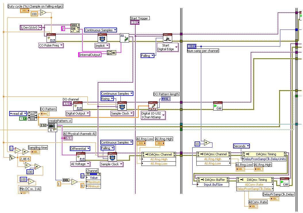
I want my PCIe-6321 to send two custom signals (modification sawtooths) on a mirror controller. I would also like to generate output with my card at the beginning of each tooth of saw. Everything must be synchronized with an external k-clock signal of 100 kHz. The idea is that whenever the PCI receives a trigger to external clock, it sends two analog output voltages and when he received 1024 clock ticks it will also send a pic of triggering TTL. What I do is first prepare the map and after that in a loop sending and modifing the output values of the two signals and at the same time send a digital signal Boolean in each arch, so when's done it 1024 iterations of the loop I send an event to the digital port. Attached you can see.
The problem is that I don't know how to synchronize both. Can I use the sample clock just to the analog output? I can use sample for the two outputs clock, or do I need to use the output of the meter? If don't know how to use it here.
If I do nothing else bad/wrong, I would be grateful for feedback.
Thanks in advance,
PabloI don't know how but I find the solution. I'm generating more than a positive value (as I was triggered maybe very fast the oscilloscope has been absent there). If I put the sample clock of digital output to use the sampling/ao/Dev1 clock that it doesn't, but if I put to use the same source as the OD (terminal where my external clock is connected), but the trigger to start the DO to be Dev1/ao/StartTrigger this works. I don't really know why, but it does.
Thank you for your patience and your help. I put here the final code.
-
Implementation of multiple digital outputs with a box USB-6009
Hi all
I write the code to implement a USB-6009 multiple digital channels, digital outputs independent. I have configured the function of "DAQmx create Channel" to create 'a channel for each line', but I can't understand how to access and control these channels separately. Pointers would be greatly appreciated.
Thank you!
I thought about it. Never mind.
-
Digital output with timer (Simulation)
Hello everyone, I just found out how LabVIEW program a week ago. I try to do a simulation of digital output by LabVIEW (my attachment). In this simulation, I have a slider as an input (0-10 V), two digital controls (upper limit and lower limit), a waveform graph draw these 3 evaluates and two Boolean LED (P0.0 and P0.1) as indicator. In this simulation, you can fill any number (between 0 and 10) in numerical order as a limit for your entry cursor. If the entrance of a cursor exceeds these upper and lower limit, then the Boolean LED lights, P0.0 so exceeds the upper limit, and if P0.1 exceeds the lower limit. The problem is that I do not know how the timer for those Boolean LED. As an example:
(1) make an entry of cursor,
(2) if entry (1) exceeds the upper limit, P0.0 lights for 5 seconds, then turn to during 10 second.
(3) if only 10 seconds, you change the entry back to normal (between high and low limit) then P0.0 will stay turn of until the cursor entry exceeds the upper limit again,.
(4) If, in this second 10 you has not changed the entry (the stay exceeds the upper limit) then P0.0 repeats the process (2) until you the entrance to cursor back to normal.
(Same process for entries exceed the lower limit).
Can you help me do this timer? Thank you

Concerning
Juventom
Hello
If you don t mind I would just give you some advise to your code. To determine the data stream you can also use only the error wire connected to the loop. So Don t you really need, it's beter not not to use variables. For your solution, you can use something similar to what I tried for the upper limit in your program. It is added as an image.
Hope it helps
-
Simultaneous analog inputs and one digital output (with NI6221M). Critical moment.
Hello!
Please excuse my bad English.
Idea:
I developed a device to measure the absorbance of light in the sample. The device will have 20 light emitting diodes (led) and 30 light sensitive photodiodes (DP). I have a PCI NI6221M card. As there are a lot of LEDS and PDs the device must use external multiplexing (MUX). The Assembly is shown in figure "DOAI System.JPG". "delta t" figure is not important. It may be zero, one or a few Americans. It is not essential for the operation of the device.
Opreation:
PD 1 will be multiplexed to the AI and the LEDs blinked (turned on and outside), one at a time. Then 2 PD will be multiplexed to the AI and again all LEDS flashing one at a time. The sequence continues with 3 PD, PD 4 and so on. Each blink a led should produce a sample of I. The sampling frequency of the AI should be about 12 kHz (so 80us for example).
Q: It will be possible to obtain from the Commission of NI6221M?
Problem:
I realize that there will be problems. When c generates an address on the MUXs there will be a delay until the LED driver, PD and input amplifier electronics of HAVE it settled. Q: Is it possible to delay the sample clock HAVE some 10 microseconds as to allow that to happen? (Perhaps use an internal counter operating on a basis of time much faster than 12 kHz sampling or use another for me still a feature is not known. May actually leave the sample clock HAVE be the 'master' and instead of delay clock.) Please see the "" calendar of GOT it. "" JPG ".
Q: Is it possible to control the time to settle for AI? That is to say that he can use the 6221, say, 30 US to settle before it reads the value. What these 30 arrive us before or after the flank of sample clock?All reviews are much appreciated,
Markus
Hello!
Just thought I should fill this thread by posting the code that we use now. The moment is as before, but we've added a few nodes property to coacha few parameters. In addition, 6221 has been replaced by a 6259Usb device that allows us to have the best insulation galvanic and more synchronized digital I/o lines.
-
Synchronize the pci-6254 and cDAQ-9174
Dear all,
I hope you enjoy!

I intend to synchronize two cDAQ-9174 chassis for an application where I need to acquire data of 8-Thermocouple, voltage 3, 1-Full bridge (strain gauge) and channel 2-meter at the same time. This enforcement action is based encoder (quadrature with 1024 ticks per round) and I need to acquire data very fast and synchronized in all channels!
I bought the material and I'm going to set up 3-voltage channels in NOR-9221, Thermocouples-4-NOR-9211, 1 strain of NOR-9237 and 2-meter gauge in NOR-9401 first cDAQ-9174 chassis Modules. I will then put remaining Thermocouples-4 in the second cDAQ-9174 chassis.
The question is whether it will work?
If Yes! Then, kindly help me on how to have synchronized it data from these two cDAQ-9174 chassis with all such modules as mentioned above?
I hope someone can help me with that and can guide me to do this task! I'm using Labview 2009 with NOR-DAQmx 2009
Kind regards!
Tajim!
A few comments after looking at your code:
I don't understand what you're doing with cancel in the task of counter.
You try to use the encoder as your sample clock? You can do it for the module 9221 and NI 9211, but it will not work with the NI 9237 as I mentioned above. You can move the NI 9237 in a separate task and from there, you have a few options depending on how you want to synchronize.
How many times you expect to get your clock on cDAQ2Mod3/PFI0?
-
What is a digital output (DO) good for?
Actually, I wanted to use the outputs digital to move from a 24 VDC circuit (to turn on/off other devices etc.).
But the current output outputs digital is so low that I have even impossible to pass an opto-coupler (opto isolator).
That's why I wonder you use outputs digital for if you cannot use them to change anything?
Of course, I can create a circuit MOSFETS or transistors to switch 24VDC power with the TTL 5V digital output signal. But I guess that most of you do not :-)
And of course, I know that I can buy OR relay modules/cards. In fact, I have many digital outputs available and do not want to buy new modules/cards.
Now, I can test and actually I get 10mA @ 5V on a digital output of NI 9401 (DIO), using the digital output to pass an opto-Coupler.
It seems that the information contained in the data sheet are supposed to mean something else...
-
Digital output to a different voltage?
Hi all
I finally finished my program of data acquisition for the laboratory, which made the acquisition of AI voltage multi-channel digital outputs with timed to control the gas valves. My post-doc asked an additional feature, however, which must be able to have the analog output... It turns out that what he really wants to do with the feature is to have output digital, but with a different voltage value (he never hears on the sending of information higher or lower in a simple experiment).
Now, the program is set up to run digital output now, it would be quite a bit of work to change in a zone of OCCUPATION. Is it possible to simply change the settings somewhere to have the ups to DO at a different voltage? I hope that this is the case from a card of 10 dollar Arduino can do 5V or 3, 3V. Our DAQ card is the NI PCIe-6353. I looked through the data sheet and found nothing.
Thank you.
p.s. I suggested using additional circuits to set the tension for a given experiment. The post-doc said it was possible, but inconvinient. :/
RaymondLo wrote:
p.s. I suggested using additional circuits to set the tension for a given experiment. The post-doc said it was possible, but inconvinient. :/
Well, it is just too bad for the post-doc. Maybe he should give you better requirements next time

OK without being in a bad mood, it is not a way to change the digital output voltage. When you talk about DIO cards really aims to communicate only high or low and have a voltage. The only other option would be to use 4 AO ports on the card and treat them programmatically as DO.
-
Hello
I'm working on a project that requires two outputs digital signals at different frequencies. Frequency of the phase 1 is about 1 kHz and is modulated on and off to a pace that will change during the execution of the program. Wave 2 passes from 1 kHz to about 6 kHz while needing to be pretty accurate to the tenth of a Hertz.
Initially, I tried to manage the simultaneous output of signals at different frequencies using a single task on a single 9477 daqmx in a cdaq-9174 chassis. As far as I know, the best way to get a specific frequency in a waveform output is to set the sampling frequency up to 2 times the frequency of the wave that is generated and generate a waveform that is given to each clock cycle. This works very well when it comes to a gesture, but I was unable to get the frequency of the modulated wave (wave 1) remains constant when the frequency of wave 2 modified or vice versa.
I have a few other modules lying around (another 9477, 9403 and 9476) and I thought I would try another task running on a separate module. I find myself receive error-50103 message if I add these modules to my cdaq chassis and run one of the waveforms of a task set to run on the add-on. Is there a way to bypass this error? I guess it would cause by running two digital output on the cdaq-9174 tasks at the same time, but it seems to me that this wouldn't be a problem with an additional module.
How can I have two outputs digital signals, running at the same time, maintaining their independent frequency frequency of the clock of the other sampling rate changes. In addition, because the wave 1 is enabled and disabled at a defined frequency, I use it to set the number of samples to write when you write a range of waveforms in the module (when generating these two waveforms on the same module).
I'm sorry if the explanation was difficult to understand. I've attached an example of error 50103 lifting. This isn't really a part of my project as a whole, but it is the easiest way to reproduce the error.
Thank you
Hi awol.
I have a follow up for you. You encounter the error because the cDAQ chassis has only a timing engine of. You will not be able to perform simultaneous tasks of the call by the hardware. Please see the following knowledge base: http://digital.ni.com/public.nsf/allkb/5E0B829E50ADE1BC86257AC50062B2D2
Mike
-
How to speed up loop DAQ triggered using NOR cDAQ-9174 with NOR-9215 and NOR-9402
Hello
I use LV2010 and NOR-DAQmx 9.2.2. I have a NOR cDAQ-9174 with a NEITHER-9215 4 channel 100 k simultaneous ADC and NOR-9402 4 channel DIO module trigger and reset.
We run WinXP sp3 on a Dell M4400 core 2 duo @2. 26 Ghz.
I used the code example NI DAQmx for acquisition of tension with trigger HW. My goal is to try all 4 channels on the 9215 simultaneously when a trigger is received on channel 0 of the 9402, after data is read, I use channel 1 on the 9402 to reset the trigger of the target material. I have a version of this work, however the maximum event rate is ~ 16/second. I have the Setup 9215 for finite samples / 10 samples per channel which is ~ 400uSec of conversion time and I realize he is above in the appeal of vi, but ~ 50mSeconds worth?
The target detector can put out up to 1 k / event triggers / seconds. Only, I received a rate of 8 per second and I added the NOR-DAQmx control vi driver and chose "commit" this did double the rate.
My question is what is the maximum rate of loop for these devices (trigger/conversion/reading device / reset) and start over? I noticed that just let free the 9215, carried out using the 'Acq & chart internal strain Clk' raised only the rate of events up to 20 Hz.
Thank you
normbo663
Hi normbo663,
You can get this works far better assuming you have an available counter (there are 4 on the backplane of the 9174).
DAQ Compact supports the tasks of meter output "redeclenchables" that can be used to generate a finite pulse train. You can set a task of finished meter redeclenchables output to be used as sample for your task of analog clock. The task of the meter output will be re-Army (less than 12, 5-25 ns) as soon as it's finished out the last pulse. The task of analog input would be configured to run continuously, but it would only sample based on the output of the meter triggered. For an example, see here.
You can reference the internal counters on the cDAQ without signals through a routing module using: cDAQ1/_ctr0 (right click on the chain counter control, then select i/o name of filtering and check channels internal to add these options to the drop down).
Thus, with the tips above, you should be able to immediately re - arming your analog acquisition on the 9215 using one background basket counters. It seems that the second half of the application is to use a second channel on the 9402 to reset the trigger of your DUT. You can deterministically generate this signal so by configuring a 2nd redeclenchables meter out task (single pulse, but this time). All you need to do is the initial delay on the appropriate value for your analog acquisition. Trigger this counter on the same PFI line that trigger you your analog task from.
Using counters to generate the signals you need in a deterministic way, the loop becomes is no longer a problem (as long as your input buffer does not overflow). You may need to re-read several triggers at the same time for the loop to keep (for example to read 1000 samples each, which would correspond to 100 triggers 10 samples).
Best regards
-
DASYLab w / support NOR-DAQmx NI 9227, NI 9229 & cDAQ 9174
I am trying to use DASYLab 11 w / NOR-DAQmx 8.5 to my configuration material of NI 9227, NOR 9229 & cDAQ-9174. After decommissioning of my PC Win7 for XP that takes in charge OR-DAQmx 8.5 (the OR-DAQmx last, supported by 11 DASYLab), I discovered that NEITHER-DAQmx 8.5 does not support the cDAQ 9174. Right now, looks like I'm watered except so use LABView. Is there any other way at this time to use this hardware configuration with DASYLab or any other application?
DASYLab V11 supports Windows 7 when you install the Service Pack (see www.dasylab.com).
Where are we going to say that it does support NOR-DAQmx 8.5? I installed the most recent NI.com last week, and it seems to work very well. I use only simulated devices so far, but DASYLab is data collection and display correctly.
-
Increase the frequency of sampling on the cdaq 9174 with neither 9212
Hi all!
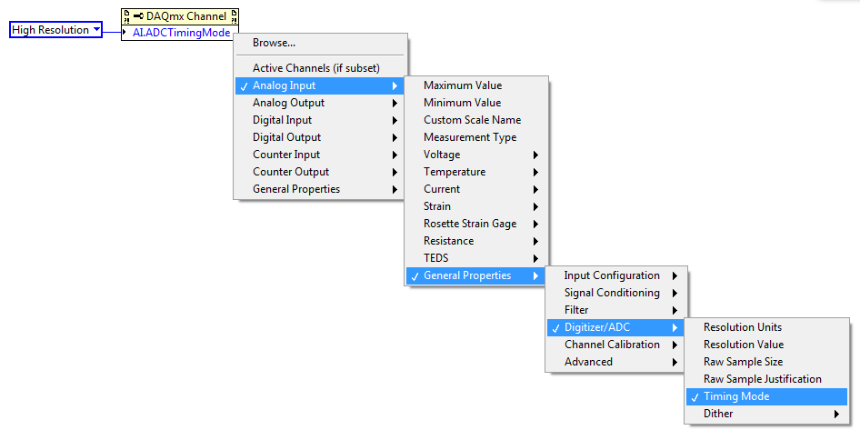
I am trying to increase my sampling rate on my nor 9212, that I use with a cdaq 9174 and LV 2015. Apparently, the sampling frequency depends on the time of conversion and can be changed between the high speed, the Best 60 Hz rejection, best 50 Hz rejection, and high resolution. (see http://www.ni.com/pdf/manuals/374358a_02.pdf, page 6). My maximum sampling frequency is 1.8 Hz, which indicates the use of the mode of synchronization of high resolution
I found this documentation explaining how to change with a crio:
http://zone.NI.com/reference/en-XX/help/373197D-01/criodevicehelp/cRIO-9212_rt/
However, I can't change it when the module is not in my project with my cdaq. My question is: How can I change the conversion without a crio time?
Thank you very much!
X0N0
Hi X0N0,
There is a DAQmx property for this:
You are welcome!
-
analog sync of input with the onset of the digital output
I'm trying out an analog signal to a file with a specified frequency samples. I also need a digital output to trigger a measurement at a frequency specified on a separate system. The frequency is controlled by the loop exits and timed when the iteration number divided by the period is exactly a whole number.
Both outputs work. The problem is that they are not synchronized. The analog output amounts to about 0.5 ms faster than the digital signal. (I checked with an oscilloscope) They both start in the 1 ms each loop runs for, but I really need them to start at the same instant. What can I do to synchronize? Also, if I'm going in the wrong direction complete, please indicate.
I use a card PCI-6723, which I think someone at some point, said not having a material sample clock. That's why I try to use a timed software loop.
Hi NEA.
You must use the 6723's built-in calendar to accomplish what you want. As the digital output subsystem is only clocked by the software, an appropriate solution should be to use one of the counters to the pulse output.
The attached code should show how. You can use the counter to output a pulse all samples of the AO N task. Material requires the initial delay to have a minimum of 2 ticks, so the meter will be behind the task of the AO by 2 samples in this case. There are different ways to work around this problem if you need (for example write two samples of 0 first).
Best regards
-
cDAQ-9174 with modules 9225 and 9239 for issue of power measurements...
Hello to one and all.
I do turn a cDAQ-9174 with modules 9225 and 9239 to measure the voltage (120, 208-240, 277 VAC) and current (via the clamp amp i400, Fluke - 10mA/exit A) respectively.
I have the set scale scale Differential No. (1:1 I guess) for 100: 1 for current and voltage. With the acquisition mode set to "N samples", 10 samples to read, at the rate of 500 m. This feeds into 'EPM_Power.vi' (polymorphic VI of the palette of EMP... can be downloaded here, http://sine.ni.com/nips/cds/view/p/lang/en/nid/209826)
I try to check my numbers with an Analyzer of power quality of 435 Fluke and supporting that upward is a Fluke 179 True RMS DMM with clamp amp i200 (for current playback)
Now, I'm running is my numbers I take data look like they're following a curve of fishing... the averages are on the right, but when my blood pressure is expected to be relatively stable, it's over the map... same story with my current readings. I tried several different filters without success. I would like to have relatively stable values for voltage and current so my other values are correct. Is there a signal conditioner or filter that will help with this?
As always, a point in the right direction would be greatly appreciated!
Thank you!
Chad
Hi, Will,
Your request for a screenshot actuall lead me to the solution. Not enough samples! I took little data too slowly and only seeing part of the wave of fishing AC each iteration. .. that became glaring when I tried to this graph. So I increased my sampling of 100 to 5 Hz and things seem to have settled things down a bit. Thank you for the good question!
SH?
C
Maybe you are looking for
-
Is it possible to install Android on Toshiba Journ.E touch?
Is it possible to install android on Toshiba Journ.E?If Yes, what and how? + The message has changed: the content has been translated.
-
I can't unlock my iPhone cell password?
I can't unlock my iPhone cell password?
-
Envelope is stuck in the printer
I tried to print envelopes of normal size and he is stuck somewhere in the HP Deskjet 5440. Can not see at all. Thanks for any help.
-
install Windows 7 on TX2-1020 - on Vista
Hey people My TX2-1020us really seems to be stifling lately, even on things simple (as only having explore open, alone). so I thought I would try to install Windows 7 Ultimate on it. for the moment, running Vista Home Premium, pre-installed (with all
-
I can't open a picture when I use photoshop.
Original title: C... Hi, I have a problem with my c... whenever I started to work with Photoshop, I can't even open a photo, he said that the scratch disk is full... clean your... I defragment and used CCleaner, releases its just some space and there