digital signals at the same time 16
Hello
I used a PXI-6254 adapter connected to the scb-68 and I try the digital output signal 16 on port 0 at the same time, so I chose to use the connector 1 port 0 line 8-23 but I can't outpul all the signal, he works for line 8-15, but for the rest, 16-23 does not work and I do not know the reason.i join 6254 board configuration and vi that I use
Hello bobogool,
I have taken a look at your code and noticed you write only FFFF, who would write only the first 16 lines, 0-15. Did you follow the first 8 lines of activity? If they work, I recommend that you add 8 extra bits, up to 23.
Tags: NI Hardware
Similar Questions
-
Hello!
My problem appeared when I tried to update my traditional NOR-DAQ legacy code to DAQmx.
I use 2 meter (meter 5 and 7 meter) on PCI-6602, to generate trains of pulses, as well as the lines of e/s digital port 0 (the form lines from 0 to 7). What I do in my request, it's that I'm starting to generate the pulse train on the output of 2 meters and after that I play with the State of digital lines.
Traditional, it was no problem to use the meters and digital lines at the same time, everything went perfectly, but in DAQmx, is not possible.
What's happening: I start generating train of pulses on the output of counters, no errors, but when I try to change the State of a line of digital port the generation of the pulse train is stopped. What happens when I start the task associated with the digital way.
My question is: is it possible to create a channel on digital lines without changing the channels created for meters?
Another thing that I managed to do with the panels 'Measurement and Automation Explorer' and Test for PCI-6602, is basically the same thing, I generate trains of pulses on the output of the 7 meter and try to start a job on the digital line, but I get an error:
"Error-200022 occurred in test Panel.
Possible reasons:
Measurements: Resource requested by this task has already been reserved by another task.
Device: Dev4
"Terminal: PFI8.On the contrary if I use the counter 0 or a counter 1 to generate trains of pulses I encounter the same problem.
What resources are used by 2 to 7 of the PCI-6602 card counters and the counters to 0 and 1 do not use?
Thanks in advance for any answer!
Ciprian
After doing some real tests on this device, I found that it is a normal behavior for the jury of 6602. This is because when you start a task digital all 32 lines are configured for digital i/o, so it replaces your meter operation. The article below the link explains a little more on this subject. You must start the digital task before the task of counter to use the features of both in your program.
2 meter and above will not work correctly when you perform digital i/o on NI 6601 or 6602
http://digital.NI.com/public.nsf/allkb/43F71527765EEC3886256E93006CD00C?OpenDocument
-
Why can't acquire data from strain and resistance at the same time with a NI 9219 module?
Hello
I use a chassis with a NI9219 module 9172 cDAQ to try to acquire the strain and resistance at the same time, with the Labview SignalExpress software. Is this possible? When I try to display two values of signal at the same time, I get an error of assistant DAQ 50103 'the specified resource is reserved. The operation could not be performed as indicated. I used to be able to acquire the strain and tension at the same time, but now even that gives me error 50103. I have hours trying to figure this out. Any help would be greatly appreciated.
Thank you
Justin
That's all! Thank you very much, now I can sleep tonight - seriously!
Thanks again,
Justin
-
Can I use USRP 2 channels at the same time to receive a signal?
Hello world
I want to do an implementation of the time difference of arrival between two receivers (antenna) estimate. I have a kit USRP, Remora and two antennas. There is only one signal source (it is transmitted in nowhere is not serious).
Can I use two channels at the same time the USRP to receive a signal?
I need the original source signal and the delayed signal version.
Thanks a lot for your help.
Sincerely yours.
Uysal.
Hello
I found this post on the forum that can be useful for you. Looks like you can not receive two antennas in the way you describe. I think that this would require a configuration USRP two.
-
I have a DAQ Assistant configured to read 2 channels at the same time. When I have a graphical indicator of wire to the output, I see 2 signals mixed together. How I divided them into separate signals?
When I wire any type of indicator, it is show that a release of a single channel.
I want 2 indicators showing 2 different signals as expected from 2 channels configured. How to do this?
I tried to use split signal but it end by showing that 1 out of 1 signal two indicators.
Thanks in advance.
Yes you are right. I tried, but I don't have the result.
I just find the path. When we launch the split signal, we should expand it (split signal icon) by top, not the bottom. It took me a while to understand this.
Thank you
-
Continuous 5V output and signal of Stimulation at the same time
Hello
I'm out a constant signal to 5V to power a testbed and output a signal of stimulation (create a small magnetic field, etc.) at the same time. I try to use DAQassistant with several output channels, but I can't fix an AO0 data set and the other set of data in AO1. Please notify; my code is up to this home.
Thank you!
Emily
Many DAQ cards provides a constant voltage of + 5V output. DAQ hardware do you use, and there a such output? If so, use instead. It will manage a current higher than an analog output. The analog output lines are not designed to power no matter what, they are purely for signalling.
-
Output signal analog two at the same time with the SCC-68. Is this possible?
Hello!
I plug in my SCC-68 two things. You're driving in the ao0 (22 screw terminals) and aoGND (55 terminal screw) and a speaker in ao1 (terminal screws 21) and aoGND (55 terminal screw).
I'm trying to generate a sugnal ao1 sine and a DC ao0 signal. Separately, they work, but at the same time they do not have...
I had try in Labview SignalExpress and also...
Any help?
Thanks: Koli
Hi Koli,
already use you it in your code. The vi s Express that you marked with ao0 ao1. :-)
Mike
-
acquisition of wireless signals and record the signal as text at the same time for 5 minutes
Hello
I'm wireless ECG signal and the display in waveform graph. And at the same time, I need to save it as text for 5 minutes. The problem I faced is for record of the signal, I use scripture to the extent file that saves the file as text... but everything by saving the trace speed decreases.
I'm very new to labview so please can someone me if Miss me something in it... Please help...
Why people always post photos of their screws rather than the screws themselves or at least excerpts? We can't tell from the picture what Version of LabVIEW, you use (so if we post code, you will not be able to open it), and we can not 'play' with your code and try without, ourselves, by hand, trying to recreate your diagram (sometimes very small). Please, help us help you!
This is in any case helps to familiarize yourself with the design of producer/consumer model.
- Open LabVIEW.
- Click on 'File', choose 'new '.... "(no new VI), then (in models) producer/consumer Design Pattern (data).
- Study the model and adapt it to your problem.
The producer would be anything that generates data. Once you have the data, you put on the queue and send to the consumer for the entire treatment. The idea is that the producer has an inherent calendar that he must answer, otherwise you lose data points. The consumer, on the other hand, just need to follow 'more or less' (in fact, the queue may / will develop, if the amount of data is not megabytes, so the consumer can really be quite slow, if you usually want to consumers, on average, to be at least as fast as the producer).
Bob Schor
-
Hello
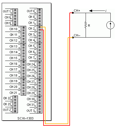
I'm trying to use two sensors of moisture Omega HX85BA and experience two CFI mass flowmeters in current loop. Humidity sensors have three outputs 0 - 10V, while flow meters have two outputs 4-20 Ma. Can I have all four sensors to wire to the same block of connection SCXI-1303 and read all the signals in the same VI? the block is connected to an SCXI 1102 b card and a 6052E DAQ of NI PCI card.
Thanks in advance!
Hello BBalmforth,
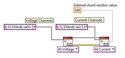
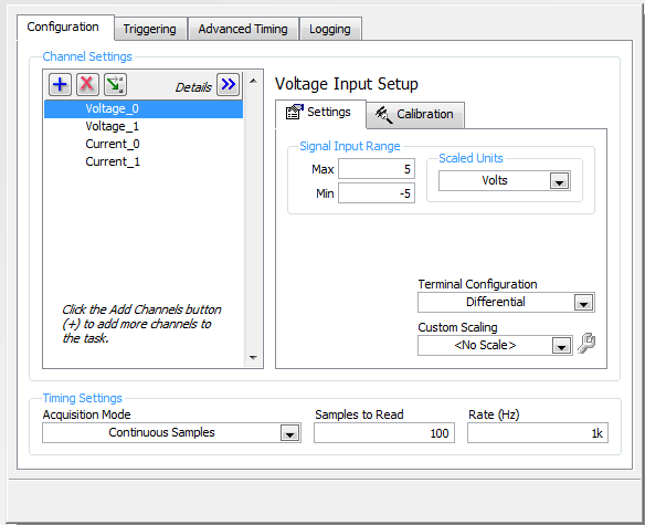
Yes it can. Although you will need external resistances (I recommend resistors precision for better accuracy) for current signals. The SCXI 1102 b is indirectly measuring the current by measuring the voltage drop across the resistance. The table below describes the current diagram and how it will seek in LabVIEW and DAQ assistant.
Wiring diagram
LabVIEW
DAQ Assistant
Kind regards
Izzy O.
Technical sales engineer
National Instruments
NI.com/support
-
At the same time entered into a local variable of a digital control while maintaining control.
Hello world
I'm quite new to Labview please bear with my lack of technical terms. I also want to apologize in advance if this topic has already been discussed somewhere in the forum.
I'll try to be as brief as possible - I will use Labview for controlling the speed of a DC by PWM motor and want to simultaneously have 1.) control button which allows me to vary the PWM (0-255), and 2.) be able to 'fix' the value of the command using the indexed values.
To better illustrate this point of view please the VI attached. When you run the code what I can do is change the value of the control by using the indexed values. So going back to my question - what changes should I make to the code in order to have the choice of using 1.) (and 2.) at the same time?
Any help would be greatly appreciated!
After extensive research on the structures of the event and property nodes, I finally found a solution.
Is attached the working version of a button control that can be further manipulated by a secondary control, but still maintain it's own control capabilities (IE not the substitution or the line of the error stream)
I hope that someone in the future will find this useful!
-
How to create impulses cause a pulse width Variable AND at the same time
Hi all
I have a NI PCI-6251 that comes with 2 counters, a FREQOUT port and then some DIO, DAC and ADC. I want to trigger a pulse of variable width (easy to do with two counters) and a frequency closed, exit at the same time. So, I want to end up with a line that will display TOP for some variable time, while the other exits a train of pulses for a time variable. It is easy to do if you have 4 counters but I don't have one. Does anyone have an idea to implement these two things AND making them trigger at the same time with the PCI-6251 card?
The line is high for as long as your pulse train controlled?
If so, set up the first counter as output pulse, configure the 2nd as output continuous meter but with the internal of the first counter output as its trigger to pause (pause when it is low). Start the 2nd meter before the first.
If not, you will need to use the digital output to replace at least one of the counters (max sampling rate is 10 MHz, so this would give less resolution compared to the time base of 80 MHz counters). So you would simply write the waveform predetermined in the buffer and he clock at the desired rate and the number of samples to give the signal that you want. You need to generate some other subsystem as FreqOut clock.
Best regards
-
How to collect data on the programs of LabView and VC ++ at the same time?
Hello
There are two programs in LabVIEW and another is in VC ++. The two programs to collect hardware data.
Therefore, for the experience, it is necessary to begin to collect data at the same time and lag must be
less than millisecond (it is essential for the experience). How can this be achieved? BTW, I'm new to LabView.
I think on the use of network socket to get the message for both applications.
I was wondering if there is a better way.
Thank you.
MARK002-MAB wrote:
Hello
There are two programs in LabVIEW and another is in VC ++. The two programs to collect hardware data.
Therefore, for the experience, it is necessary to begin to collect data at the same time and lag must be
less than millisecond (it is essential for the experience). How can this be achieved? BTW, I'm new to LabView.
I think on the use of network socket to get the message for both applications.
I was wondering if there is a better way.
Thank you.
You do not say if two programs access the same material, but I guess not. Because if they did, you probably get conflicts when the two programs try to access the same material at the same time.
In either case, the only really reliable way to ensure that your needs of< 1ms="" would="" be="" hardware="" triggering.="" one="" hardware="" unit="" is="" programmed="" to="" provide="" a="" hardware="" trigger,="" typically="" a="" digital="" signal="" and="" the="" other="" is="" programmed="" previous="" to="" the="" desired="" start="" point,="" to="" wait="" for="" that="" trigger="" and="" start="" automatically="" when="" it="" is="" received.="" if="" both="" hardware="" units="" are="" ni="" daq="" cards="" you="" can="" do="" that="" fairly="" easily="" using="" the="" rtsi="" bus="" or="" in="" case="" of="" pxi="" the="" pxi="" trigger="" lines.="" if="" they="" are="" different="" hardware="" then="" it="" can="" get="" more="" complicated="" to="">
-
How can I delete all text messages from my watch at the same time
Can how I delete all messages at once on my Apple Watch?
Hello
It is not possible to delete all the messages in your Apple Watch at the same time.
To delete messages:
-On your watch, open messages (via the home screen, accessible via a simple press on the digital Crown) > when you view the list of conversation, by sweeping left on a conversation > tap Delete / Trash.
-
USBOTG and Charge at the same time on Stream 8
To keep this thread as productive as possible and efficient for those who find it useful to:
Unless you have under your eyes
1. a schematic representation of the 8 Stream USB port (USB port and battery electric circuit etc.)
2 source code for the firmware BIOS and kernel that controls the material
Please DO NOT respond or say "is not possible". In view of the above is true, you do not have enough information to say '' not possible. ''
If no one replys with a solution, what he calls not possible by default.
Also please do not answer to say ' I don't know how "or" but I know how to do anything else that ' is also not that useful.
An update of the BIOS or other software update may be required by HP, Microsoft or both to offer this feature really intuitive and quite possible.
And I hope that this thread can be an effort consolidated by all who have the 8 flow to make the necessary changes. The majority of the other tablet PCs are capable of it. It seems that only the 8 Stream and a few others have trouble with her.
~~~~
I want the ability to use a simple, inexpensive cable and perhaps standard (with electronic active minimum inside) which allows me to host and to use one or more USB devices on the Stream via its USB port B microphone 8 while this cable can also be connected to a charger standard and charge 8 flow simultaneously. This means that the cable has a minimum of three connectors. One of the possible configurations are as follows (apart from the normal charging cable):
1 cable Micro USB B Male - connect to the stream 8
2 USB male A - connect to the AC charger (IE one that came with the 8 Stream)
3. USB A female - one or several connectors to plug into the key of USB data, keyboard, mouse or even a hub.
Connector # 2. above shall provide a power supply to recharge the 8 Stream via conn. #1 and the power supply for external USB devices via conn. #3 so that they are in use - all at the same time.
A and if the same cable can act as a normal OTG no charger for when no external power supply is available. This may necessitate a switch or an electrontics active inside.
The last part of this goal is unimportant for various reasons. I wish that HP, the manufacturer of 8 flow, to State in writing good mode necessary to do this, so that other manufacturers or even-it yourself can make maximum use of their tablet HP equipment.
~~~~
The neat thing it will alow a person to do with their tablet, it is to work at home using the Tablet as a desktop PC by connecting a keyboard, mouse, perhaps external screen (with USB to the display adapter) and knit for a long time without time limit prescribed by the battery life because the charger provides energy to all involved.
If there is only a single connector on the cable #3, then an additional node of coarse had to provide support for these multiple USB devices at the same time. However, it would be better if there were several #3 connectors integrated in the cable itself. This would be better as a suitable USB hub also requires its own power. That an adapter is necessary if the whole thing were integrated into one.
~~~~
I really want answers from anyone who has already accomplished USB OTG delivered with simultaneous load with flow 8. (independent of any published 'proper' way is also welcome)
Today's date is 2015-01-16. If in 2015-02-16 (one month), nobody has posted a solution and then starts to bug HP and Microsoft on it's us?
~~~~
Technical training:
I understand the possibility the tablet software and firmware must take a decision on the manner in which power flows on the power port USB microphone B pins.
I know that with a proper design of the electronic circuit carring these signals of power inside the Tablet could be sensitive to what is connected and without risk to decide for himself what to do without needing to control software. For example by testing/detecting periodically differential voltage or current management to see what sides of the connector can supply.
But this is only one of the many "could bes".
In addition, this can be no standard regarding the standard USB. What seems to be actually the case with a lot of cables OTG + fresh, is that physical clues embedded in the cable or charger are used to signal to the Tablet what the situation is. Then the signal of software/firmware of the Tablet, interprets what the situation is intelligently and responds by flipping the bits of correct hardware control to activate, or deactivate the power flow in the port and also control its direction in or out.
I'm not familiar with the standard USB. Maybe I could do more research, if I believed that HP followed with 8 Stream or even the standard covered this situation explicitly.
But to a certain extent, it seems I'll have to invent something that should be intuitively just like it does with other tablets. Isn't it? Maybe I'm overthinking, but I can't find any USB OTG + cables load that specify compatibility with 8 HP flow.
In any case, I was familiar with both methods other use of tablets to send the highest mentioned signal to the hardware/firmware/software of the tablet to the idea that it's time to load / time of OTG or both.
The first method is a 0 Ohm to 200 ohms short between pin USB A 2 and 3. This is the bidirectional data differential lines D - and D + respectively. In data mode, all the data passes back and forth on those lines. When you load with a cable, it's the charger module that puts this short, not on the cable. I measured the short on three different Chargers. It is 0 Ohms on two of them, one of those who are the charger that came with the 8 HP flow. The others 0 ohms was generic. The third was for an apple iPad and it measured on 53KOhms. It's probably not the resistance ohms 0-200, but probably it is impedance termination indicating that there is some intelligent serial port communication in the charger itself. Leave it to Apple to be different.
This method is somewhat questionable, as this signaling mode would prevent OTG + fee because it seems unlikely that you will be able to OTG when the data lines are shorted each and overloaded with such low impedance. I could be wrong on this subject...
The other method I have seen suggested to work with some tablets and phones other than the 8 stream is too short the USB microphone B pin 5 to Terminal 4 with 0 Ohms to 100 000 Ohms.
USB B has 5 pins. USB has only 4. The extra pin on B moves the GND pin 4 pin 5 pin to and makes pin 4 PIN ID.
If this signal applies to a drop in the ID pin (4) or in some cases, I saw that she proposed, he runs down with 0 Ohms.
Dead shorting things always makes me nervous. If ID is a simple normally high impedance high input, resistance could be used to make voltage well below the low or zero threshold while also preventing the risk of damage when cheat on him with a device that you do not have the diagram for.
Yet, 100K is a bit high for a 'pull down' in most of the situations that I'm used to. Even a 10K would be uncertain. A 1 K or 2 K seems reliable enough, but then things are weaker and in know more nowadays low... All but a dead short but if possible.
So, it seems possible that the device might be able to "indicate" by the specific value of the resistance, which can be found here. In other words the resistance is not a pull down but in fact a signature analog ID, in which case the exact value will be crucial. So if this is the case, a guess is not going to work.
Obviously in such a system as described above, a chip inside the Stream 8 should be responsible to support this information. I hope the 8 Stream has such a chip.
Probably a register inside this chip would be at all times what the State of the pin ID is a binary number. All that is needed is for the BIOS to the chip and the registry in it and read this number via the bus to determine what happens to the port. Finally, he would use that signals of info to send the order of material to the electrontics of power set the appropriate direction to take etc. (and change the State of the icon on the screen of the rude)
I don't know if the PIN ID method described is a standard USB or not either.
Eventually, there may be a third way. But I do not suspect that it would be possible with a non-active external device. In any case too complicated for the novice DIY for sure.
The device would need to act is a kind of extension of bus. As an active hub. But she would use the negotiation of data USB serial lines and in addition to reproduce one or more additional USB ports, intelligently inform the tablet to get with the program which is "now we're going to otg and recharge at the same time."
This requires a smart external device with a processor Inside, no doubt.
It seems to me that many other tablets have been able achieve avecjoint here the need for a smart external device and thus the flow must also be able to do.
There is a device that claims to be able to work with the HP Jet 7 and 8 and provides same ethernet and USB and big DVI ports so loads the data stream. But its expensive because it is active. Se here:
It's called a "Docking Station".
A reference to a product that does exactly what I want (possibly without active electronic components) is here:
It's by Kirin and it is a device of type squid with four USB ports. Precisely, which is my goal. But read in the comments stream 7 user indicated that he would not be OTG and load, not really clear if it worked as a hub USB OTG or not. Another evaluator stated that she would not support even a single USB device much less fees of 8 Stream. This device has a switch.
I forgot to mention that some 'hackers' have claimed success with other tablets to deceive their devices by using a multi-step process to plug things in. Usually in general they would get connected Tablet and load first, then they would return a switch or something remove some resistance or the signal was introduced by the first position of the switch. For some reason any Tablet would continue to require. Then the data lines would be free and they would plug in a usb key and it mounts correctly even if the tablet was always in charge.
It's like the power circuit has a lock which does not allow it to return to the mode "power flow" as long as he still feels the power flows inward regardless of what software it is telling. Full proposal here.
These tips seem dubious to me. Changes in the BIOS could change the way it works. Also you can not be sure what actually happens if you do not have a schematic representation. You could damage your tablet. Many people will support icon in the operating system whether the Tablet is in charge. But I'm sort of a low-risk guy and my policy is generally indicators of intereperet not to have meaning at all once a device is functioning in a non-standard setting. Especially when it's something that I did not built and could not fix if I FRY.
Hypothetical reasoning: tell me what data sensory discs really the State of the charging light screen? This reflect the bit of hardware control programs actually feeding management and status on the port? Or does it measure the direction of the flow of power, said in the section of the circuit battery monitoring? Point - none of us have a schema because it's owner. To really be sure according to the smart electronic hardware, the port must be mode flow under advisement "of power. If it's in a "power flow out" mode and power will be delivered externally as well you wind upward with both power supplies the same power at the wheel nets. In this case, the two opposing regulators attempting both to drive 5 V can have slightly different voltage calibrations. That could lead to fighting between them, with more than 100% of their capacity. For example if you try to regulate 4.95 real V and the other and other attempts to regulate 5.05 V. Current then flows to the tune of 100 mV / a few milliohms in the cables linking the two. This may be several amperes. (many) In other words, like I said: you want the tablet to know that power is coming in don't go out and automatically hitting the internal switches needed for that to happen. Probably the icon should indicate this with precision, but in some wacky situation, he could not. There may be a chance that the icon could indicate the load and still be burning or focusing on some circuits of the tablet or the charger.
Another thing, I could see that happening is if you play with these reported resistance types enough you might find a resistance value that winds up place the device in an intermittent condition. In other words it keeps flipping back and forth quickly between OTG and fresh. It can give the illusion that it works. You can have marginal communication with your USB devices and battery could even load. But will still be a lot of stress on the power circuit.
It is difficult for me to risk a Tablet perfectly well if I don't know exactly what I'm doing.
If a brave individual makes their own experimentation and verifies that it charges and OTGs and you tell the rest of us, you're a hero.
Maybe one of you has a good knowledge on the USB standard to have more confidence in such an experience... like what the ID pin 4 REALLY supposed to work for example?
That's what I know so far. If you think you can help, thanks in advance, or if this helped you, then your quite welcome.
It works
Evidence
http://targusblog.com/2014/11/25/how-to-turn-a-99-Tablet-into-a-workstation/
But it's 4 x the price in Europe
Have fun
-
Satellite Pro P300 keypad at the same time as the alphabetical keyboard?
Hello
I'm new here, and English is not my mother tongue, so be indulgent ;-)
I have a problem with my keypad.
It is not possible to make it work at the same time as the alphabetic keyboard.When I press NumLock to make it work, there also change the alphabetical keyboard into digital.
Example: numlock on uiojklnm, = 456123n0,
I have a QWERTZ keyboard.
Thanks for your help
see you soon
ValWhat model of laptop do you have?
You update the BIOS?If not, try most of the problems can be solved by the BIOS updated!
Maybe you are looking for
-
I have my email is tiny I didn't adjust my computer settings how concrete this action
I was checking my email I went to compose a letter everything went really small, I don't know what was going on.as I continued to write my letter to someone he still smaller, please can I have help with this thanks is there a way to investigate with
-
Do not load Web sites. Only blue title bar appears.
Often, site Web doesn't completely load the first time. Only the band thin blue title appears at the top of the page. The rest of the page is blank. Usually, the page will load if I re-click on the link, but it's a gene. What is the problem?
-
ProBook 4740 s: HDD Test failed
The system says there is a failure on the hard disk check and I think that is the problem of battery who told me that it must be calibrated. Any expert can help? Failure ID: 9GDXGM-71P82A-QFPJW1-60QJ03
-
Graph of a table, but not all of the ranks of it?
I'm graphic of a data table so that several waveforms appear on my graph of the waveform. The table has 500 lines, but I will not draw everyone, only the first row, 20th, 40th, 60th,..., 500th row. I was thinking of using a loop for to extract the li
-
Is there a totally free utility to free up space on my computer?
I am trying to find a way to clean old unnecessary files to free up space without using disk cleanup. I used it and it does not all at the same time.