digital triggering of stop/start of analog data acquisition
I want to use a signal from a digital line to start and stop analog data acquisition. The signal can change levels several times during a race of the VI so I have to start and stop several times data acquisition and store each session data in a different file.
I tried to play with the following screw: digital triggering of break, DigitalStartandStopTrigger and ContAcq_DigTrig. None of them doesn't seem to work for my configuration. I also do continuous data acquisition so I can't use a reference. I use PCI 6259 DAQ.
I used the "P0" pins rather than PFI pin on the grid BNC-2090. I know... stupid enough.
Tags: NI Software
Similar Questions
-
LeCroy Waverunner 640Zi - Data Acquisition
Hello... I'm trying to set up my oscilloscope waverunner with LabVIEW SignalExpress for data acquisition.
I took the steps so far:
1 pulse generator hooked to scope of signal generation
2 USB scope to the installed computer with LabView
3 downloaded lecroyscope driver 3.2.9 - x 64
I turn on the scope and plug in the USB to the computer and SignalExpress begins.
a. start by using data acquisition
b. Add step/aquire signal / IVI aquire / IVI brought aquire
c. create new IVI session... resources descriptor (I choose my USB device ' USB0::0x05FF:0 x 1023: 2812N61507:INSTR '), I select the right driver (lcscope), and I do not click enable simulation data, press ok
d. I still receive configuration errorse. did the research... some forum said goto MAX, find drivers and uncheck the Cache and the exchange of check
f. attempt to initialize... always get config errors.
g. return to MAX... change to simulate with specific driver.
h. initialization works... NO errors, BUT no data are acquired.
Help, please!
Hello
Sorry to jump in if I was out of the country for a while and am still catching things in my office.
I think you are looking for someone to say yes, "you can connect to the scope with NOR-MAX and VISA, and here's how interactive tool do"
A few things:
LabVIEW for XStream extended driver is the right one. It works with all the TeledyneLeCroy Windows based scopes.
As I see has already been noted. (I'll give Kudos soon), the scope of application must be configured to use interface USBTMC. To do this, go to the drop down Utitlites on the scope menu and select "utilities configuration... '. "in the tabs that appear at the bottom of the screen, select the 'Remote' tab and make sure that the interface type is set to USBTMC. This will also show you the VISA resource (I see it in the title of the image of VISA interactive tool indicated in a previous post).
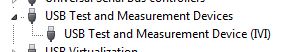
Once this field is selected, the PC should detect the USB connection and install the device. (you can see in your device manager as a Test of USB and the measurement device):
Once this is done, you can then enter the NOT-MAX and it will detect and display resources. You can now communicate with the device:
If you have problems, do not hesitate to give me a call and I'm happy to walk through it over the phone.
Kind regards
Leonard Brown
Technical sales engineer
Teledyne LeCroy
1-800-553-2769 -
extend the display time in data acquisition for more than 10 sec
I have create a vi of analog data acquisition. Everything works fine. However, no matter what I increase sampling # and rates; maximum display time is always 10 sec. I need to display the longer period time, but don't know how. Can anyone help?
Not a good VI. Where did you go?
The properties VI/execution has the checkbox next to unchecked the Autmatic error handling. And you don't have an error on your DAQ assistant indicator, or sons of the error at all. Fix them, and I bet you will see that you got a timeout error. Also, the while loop had uncontrolled Autogrow which means Add constants or change the display of the Express VI to disappear outside of the loop rather than more and more to their housing.
You do not have a timeout constant cable to the DAQ assistant, which means that it will use its default value of 10 seconds. This will cause a time-out error that you won't see because the VI property is unchecked and you don't have another handling error in its place.
-
simulateneous of analog and digital triggering
Hello
I have an experience that is very similar to this announcement:
As in the display, I need trigger out of logic AND low frequency (3 Hz) and a signal of high frequency (100 Hz). However, my experience is different because my low-frequency signal is an analog of entry (AI0) and I need experience to trigger off each edge of the signal change high frequency, while the analog input is high. To do this, I created a trigger to HAVE that starts a counter whose state high and low are similar to that of my analog input signal. I then export the output event from the meter to a port (PFI8) and pass this signal and the other signal high frequency through a door AND as in the posting linked above.
So far, everything works. I've included a VI that is just this part.
However, I then connect the output of this gate AND a PFI0 port and use it as a digital triggering to read an AI0, 1 channel. When I perform this final step, my whole system stops working, but gives no error. To troubleshoot, I measured the output of the meter to the port of PFI8 has stopped working and the port of PFI8 remains in the low state. For some reason any when I add the channel HAVE additional (AI0 or AI1, whatever) with digital trigger (PFI0), everything grinds to stop. I have also included the VI for this case.
Any ideas?
Thank you very much!
Hi Jared,
I use indeed a door AND external as described in the thread. Further research actually led me to discover that "you can't have two analog input tasks at the same time" of this thread:
So I had to build a circuit to convert my analog signal into TTL signals (for the release). I then AND'ed the two signals in the same was as described in the thread mentioned above.
-Clinton
-
Error 50103 - simultaneous analog Vout and wine with start of analog triggering
Hello
I'm stuck error 50103. I looked on the Web site of NOR and worked through the 7 cases and think that my problem is the 6 case - although I'm not sure - and have no idea how to fix this. Basically, what I would do is out my signal and have receive side save after it passes through a noisy channel. To start, I have attached a trigger control so that the transmission or recording start before the input trigger exceeds a certain value (in my case, 3V).
Could someone please look at my code (attached, called 'Optical_DPPM_V3.vi')) and try to give me an indication as to what I'm doing wrong? Thank you!
Furthermore, I use examples of OR that I have also included in the .zip for reference file.
SP
P.S. hardware: LabView 8.2, NI PCI-6070E
Hi gt3000,.
Thanks for your reply. I actually solved the problem I called one of your offices directly and spoke with someone last night.
Indeed, the problem was "case 6" as it is stated on the page you gave. "." When I spole with one of your colleagues, I was directed to an example that does most of what I wanted. If anyone is interested, you can follow this path to find:
Help--> find examples--> material input and output--> DAQmx--> synchronization--> multifunction--> multi-function Synch AI - AO.vi
It seems that the trick is to use an internal digital triggering to synchronize the CLK for VI and VO.
If people are interested, I can send my final code around for a differential pulse modulator, triggered by an external analog voltage which the receiver registers and stores the values in a worksheet. My next goal is actually write the code for the receiver to demodulate information... here go us!
Thanks again,
SP
-
Hi all
I'm new to LabVIEW
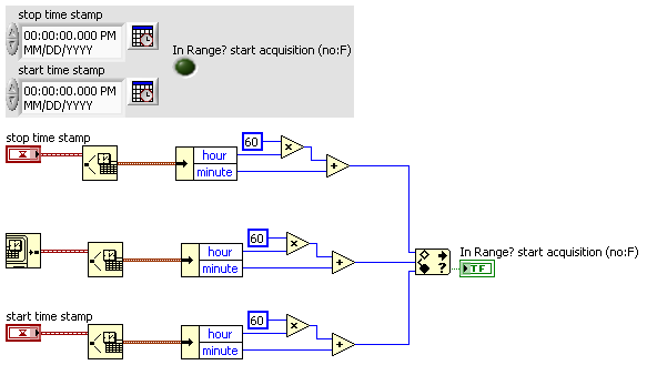
I want to create a program that can start acquiring data at 05:00 and stop at 19:00 and restart at 05:00 in the next day and so on
The ilustration is as below:
05:00 September 20, 2012 beginning of data acquisition
19:00 September 20, 2012, stop data acquisition
05:00 September 21, 2012 beginning of data acquisition
19:00 September 21, 2012 stop data acquisition
and so on...
Can someone help me on this please?
I have attached the VI below
Thanks in advance

OK, ok... im just a padawan! BTW, take care of your stress points...

-
I created a program that reads analog data and draw a waveform, but I need to stop the program when the voltage drops to a certain tension. When I tried the analog edge trigger it showed the error in the subject:
Reason: The requested value is not supported for this property value. The value of the property may be invalid because it is in conflict with another property.
Property: Trig startup type
Requested value: analog edge
You can select: Digital Edge, no
I understand what the analog trigger is not available for my DAQmx version, without again getting equiptment, can I use a trigger to stop reading data at a specific voltage?
How to start and stop a similar read digital triggering?
Thanks in advance!
Ah! Well, then the Boolean value of status would be connected to the State of the thread of the unbundled error, Boolean stop to the stop button and the Boolean value to the right would be the stop for loop itself... so something like this (see image). This is an excerpt from LabVIEW 2014, so it can not easily fall in your version, but I hope it's clear enough on how you can wire it to the top.
-
Outbreak of the AO tasks with digital triggering
I'm triggering an analog using a digital triggering (PFI0) task on a NOR-6343 (USB), but don't see the behavior desired of my VI (see screenshot).
* When I shoot digital triggering (digitalTrigger = False), the AO signals appear planned (except that... they do not fire).
* When I turn on the trigger (digitalTrigger = True), however, there is no signal on the channels of the AO.
* I tried two different sources: PFI0 and the clock internal (set both rising edge). For the PFI0 channel, I connected a function with a wave generator square 5 v (the PFI0 had a slow rise... time "I think I could solve this problem by adding a small circuit of buffering). However, I expect it should work correctly using the internal clock as a trigger.
What's wrong with my code / setup?
A few follow-up questions:
* This will trigger the installation program not start indicator AO once? Or the trigger will cause the task to start whenever the finished AO signal and the trigger goes high? (I wish that it behaves like the latter)
* Just to check: the response rate of the AO task to the digital trigger should be of the order of 1 MHz?Hello kllurie,
What do you use the trigger for? The way you have the task to put in place now, it will run continuously until you press the STOP button and ignore any input trigger. If you want to be able to have the task to complete and start over with a digital triggering, you make the task two finishes and Retriggerable. You can configure the task to be finished by replacing the constant continuous samples on the Timing.vi with finished samples and giving him a number of samples to be taken before stopping. Then you can do the task Retriggerable using the property trigger DAQmx node and choosing Start > more > Retriggerable sometime before the Start.vi.
As to what it should be used as your relaxation, you'll want something with a fast rise time (so that it is detected as a numerical advantage) and is not as fast as the sample clock. If you use the sample as your trigger clock, there would be essentially no difference between your redeclenchables task and a continuous. It would end the collection of samples and then immediately redeclenchee.
Let me know if that answers your questions!
-
Slope of digital triggering NI SCOPE
I have a problem, try to use a digital triggering with a USB-5133 digitizer. I use NO-scope (3.5) and C. My software doesn't seem to be able to change the slope of the trigger (using niScope_ConfigureTriggerDigital()). There is no problem if I use an analog trigger.
The problem is not related to my code. I see the same behavior with the NOR-SCOPE Soft Front Panel (version 2.9). In this application, if I connect the trigger PFI 1 entry and select digital triggering, then the selection of the slope has no effect. However, by selecting briefly "edge" trigger, change of slope in this mode and back to digital triggering, I find that the trigger is now working according to the slope in the edge, trigger mode.
Although niScope_ConfigureTriggerEdge() seems to work o.k. (using an analog input) and is not niScope_ConfigureTriggerDigital(), the following sequence does not provide a work around:
niScope_ConfigureTriggerEdge (...);
niScope_ConfigureTriggerDigital (...);
The entrance of IFP 1 seems OK, even though at the start I had been feeding it straight V CMOS 5 door. Adding a separator line at the entrance to the tensions between 0 and 2.8 V had no effect on the behavior.
Hello Bmetz,
It is a known problem that has been fixed in version 3.5.1 OR-scope. You can download and install the update through the page drivers and updates here:http://joule.ni.com/nidu/cds/fn/p/sn/n23:3465.40/lang/en
You will find a list of bug fixes in the readme, including the following:
123308: Fixed problem
with incompatible trigger when to change the edge of triggering on the NC
USB-5132/5133.Hope this helps,
Jennifer O.
Product Support Engineer: scanners high speed
-
Digital triggering Vs software relaxation.
I'm running a DAQ USB-FS1608 of MCC to measure multiple channels of analog voltage. I also have a digital camera from a regulator of frequency MTS 407 TTL. Inside my VI, I read a signal rising TTL of the Multilateral trading system, send a signal to activate the digital output, then I start my acquisition of data. 1 Hz, it would be better to control my digital output, (which sends a command to execute for the Multilateral trading system, which then operates a hydraulic piston) with a hardware trigger?
Yes, you must connect the signal you want as digital input on the TRIG_IN channel, and then keep the same wiring to your digital output.
-
Digital triggering PFI on a cDAQ-9188
I use a Campell data recorder to send a pulse of 5mV to my daq to trigger the recording of some accelerometers. I also have the code to stop acquisition when another pulse is sent, the code has currently a predefined sampling time how I would change.
Thank you very much
I'm glad that it worked. You get with the other examples?
There is a slight difference between the former and the latter. The one you posted just checks for the trigger of the judgment in software rather than in hardware, so you will be limited to verification of the digital line as you take more analog samples. If it works for you, but then that's fine.
One thing I would recommend is a stop button, so you can stop the loop if you want, without having to give up the program. It will ensure that you clear resources etc.
-
Acquisition of data stops at data acquisition
Hello
See the attached VI. Data acquisition acquires data without problem for a few minutes, and then suddenly the event structure does nothing but the timeout. I'm deliberately ignore the 200279 error that is generated when two triggers are too close to each other, because I want to just ignore these triggers, but perhaps which also prevents tasks at a certain time? I also tried to start and stop the task again in the case of timeout events, but it does not help (it causes an error). Is there a way to prevent either the DAQ card (I use the box USB-6251) of the judgment of the data collection or a better way to ignore triggers that are too close together?
I hope that I am making some sense here :-)
Thank you
Jeremy
Jeremy,
Thanks for letting me know about the 99% CPU usage. It is definitely the cause of your accident and can be avoided by putting a funtion waiting with maybe 10 milliseconds in your timing loop. However, if you want to keep avoiding strict with no node blocking, you will need to restructure your VI to use the Express VI of time elapsed since the range of Timing. You will find examples of the use of this VI in detailed at the bottom help.
Hope this helps, have a great weekend!
-
Digital input to Toshiba 46TL-> no analog audio output to amplifier
Hi all
When I connect a video source (e.g. computer laptop via DLNA) to my 46TL, output TV audio analog (red/white taken connected to an amplifier) does not work.
It does, however, watching television.
Is it possible to configure the TV to read the audio data from digital input (HDMI/DLNA) to the analog output?
Thank you for the help
Not quite what series of TLxxx you have, but for example the TL938 supports a digital (optical) audio output port that provides a digital audio signal.
Why n t connect the amplifier to the TV using this Jack?Connectors for component video / audio to the rear of the TV are the ports of ENTRY and not the OUTPUT ports. So, you can send an audio signal to the TV and not the amplifier output.
-
data acquisition stops automatically
I want to stop assistant DAQ automatically after a period of time, so I created this VI.
When I start the program, it work and after reaching the value of time specific 50, the graphical indicator ' looks like "stop, but wait after 9999 second, the graphical indicator suddenly see a lot of data that seems to be taken for the 9999 seconds, what is happening? After that, it gives an error saying:
Possible reasons:
Attempted to read samples that are no longer available. The requested sample was already available, but has since been replaced.
Increase in the size of buffer, most frequently the reading of data or by specifying a fixed number of samples to read instead of reading all available samples would correct the problem.
Property: RelativeTo
Corresponding value: current playback Position
Property: Offset
Corresponding value: 0Task name: _unnamedTask<100>
Data acquisition cannot be stopped like that?

Thank you
Not quite. Like this.

-
Photosmart C6180 problem of Power-Up/Power-Down - loops on/stop/start/stop etc.
I had the C6180 Photosmart wireless connected to a Mac OS X 10.5.6 laptop Macbook Intel and IBM PC XP SP 2 for more than 2 years. I did have major problems with the printer.
Recently, I have known a couple of electric in my house. Since then the printer has turned off randomly once or twice. Today the printer began to turn off/on/off/on/turned off/turned on etc.
It lights up and shows the HP logo and process bar animation for one minute, followed by the message: "abnormal termination. To avoid damage on the button to turn off the printer. Do not use a wall or the band switch to close. Press OK. Then he stops and leaves upward.
I tried to enter batch Mfg mode by organizing the * and # keys. It flashes "Mfg commands - enter special Key Combo" for the second of two, then stops and makes a loop on/stop/start/stop again and again.
I have disconnected all data cables, installs the printer in another room, closes the wifi on both computers and connected directly to the wall on a different circuit to eliminate problems of low power as the culprit. I swapped the power cable between the wall and the block of the AC adapter with the same exact type of cord of another piece of equipment with the same results.
I wonder if it is a symptom of a surfboard logic damaged in the printer, or a problem with the AC adapter?
If it is the logic board, does pay to get it fixed? An equivalent printer for Mac would cost about $200. Not to mention that I came just to have stored on cartridges.
What is a likely indication of a problem of brick AC adapter? If so, should I spring for a replacement block AC adapter for $30?
I was not able to find this question in a post on the forum and I was wondering if it's 'Au revoir' to the C6180?
Thank you for your contribution to this number
Try this:
1. If the printer is still on, unplug all rigid and flexible cables at the back of the printer.
2 unplug the power cord also from the wall...
3. wait for two minutes.
4 reconnect the power cord to a wall outlet first.
5. hold the pound (#) and six 6 buttons.
6. all by pressing the two buttons, reconnect the power cord to the back of the printer and at the end of two seconds, exit book and six buttons.
7. turn on the printer if it goes out...
Let me know the results.

Maybe you are looking for
-
Printing problem on deskjet 4510 with windows 8.1
I bought a new deskjet 4510 and have installed via usb on my desktop running windows 8.1. This isn't the impression through products of ms office word, excel etc. and either through wordpad. I can print Notepad files and pdf via adobe reader software
-
I have synced my iCloud and a new iPadAir account an iPhone 4. Contact data on the iPhone disappeared. No idea how to get it back?
-
No BIOS for USB support? Can't boot from USB HDD
Hello I was trying to install two operating systems (Linux, Windows Vista CTP) on my external hard drive (USB 2.0, Firewire). And I can't seem to-because he doesn't seem to be a way to specify the support of USB devices in your boot sequence. It seem
-
Generate 2 Trains of pulses with different frequencies and Heavy duty with a PCI-MIO-16XE-10
Hello I use a Board PEAK-MIO-16XE-10 DAQmx with LabView 8.6 to run a door for a piece of equipment controller. I need to create 2 separate, all pulse trains both trigger simultaneously, each with their own cycle frequency and duty. So far, I can crea
-
"Limited or no connectivity" error when you try to connect to the internet
Original title: loss of LAN connection I can connect to my counter top. But when I plug the line in my IBM Thinkpad T42 I have limited to no connectivity. I am running Windows XP home.