Digitization and adaptation of impedance of the signal source entries
I'm trying to measure the voltage difference and the time between the two entrances of a USB-5132 digitizer. The switching interval that I try to capture is ~ 150uS and I intend to acquire ~ 25K samples (50MS/s for 500, although it is an overdose of sampling frequency). The digitizer is 1 M ohms entered and I wanted to use the 100 SMA 50 ohm cables to connect to the source of the signals which in addition to several kohm impedance. My knowledge of RF is low and I am concerned about the impedance matching between the digitizer inputs, impedance source and wiring. What kind of considerations to I need to avoid degrading the signal? The switching signal is pulse-like and is rich in harmonics and on a sample of 500K samples/s scope is represented accurately. Should what kind of considerations I do about the impedance?
Hi William,.
There will be some problems if you try to use a source that has an impedance of several kohms. You will probably get the reflections of signals. What is the source of your signal has several kohm impedance? I'd take a peek through the following article Developer area that describes some of the considerations when it comes from impedance matching. Specifically, I would check the last section corresponding resistive. This should give you a better idea of what to worry about your application.
http://zone.NI.com/DevZone/CDA/tut/p/ID/3475#toc4
Here are also a couple more developer area articles that you might be interested in what concerns your situation.
http://zone.NI.com/DevZone/CDA/tut/p/ID/5779
http://zone.NI.com/DevZone/CDA/tut/p/ID/2892
Chris W
Tags: NI Products
Similar Questions
-
I use an analog input on a PCI-6224 and are having problems with the clock source
I use an analog input on a PCI-6224 and are having problems with the clock source. I'm trying samples of 16 different analog inputs very quickly. I have the sample mode: Timed Single Point material. The rate, that I am running is the maximum (250 kHz (15625Hz per channel)). I left the default clock source and trying to taste several times. The analogue input works for a short time (2-3 seconds) and then everything stops. I'm doing something wrong or is there something I'm missing? Any advice would be great.
That's how you samples using the sample clock clock. If you see a delay then something is wrong with how you track/data visualization.
Single point NI the hardware is for PID control with a real-time operating system.
-
How about using labview vi of the filter and multiply vi to replace the analog filter and amplifier
Hi all
I use a data acquisition system to acquire a weak signal, it seems to a voltage amplifier and low-pass filter before the acquisition of data. I was wondering, if I use low-pass of the labview vi of the filter and multiply vi to process the signal picked up by DAQ, can I get the same effect as the analog low-pass filter and amp?
Thank you!
No!
1. any system of sampled data must be band including prior to sampling in order to avoid aliasing. It is impossible to remove aliasing after collection.
2. the resolution of the DAQ system will be so low that you'll very 'fat' scanning and you will lose a large part of the information in your signal.
Sorry, but you need to amplify and filter in the material before the data acquisition device for best results.
Lynn
-
Connecting two routers WRT54G2 to extend the signal
I have available two routers wireless broadband Linksys G (WRT54G2), given to me by a family member. We use one of the routers by itself for some time, but have no adequate signal throughout our House. I decided it would be easier to design the floor plan of the House for you to see his situation compared with the rest of the House on the walls that do not. We have the HughesNet satellite internet which is on the roof just about the location of the modem and router at the bottom right of the image.
What do you think would be the best location of the main router? I read it would be more centrally located, because the signal travels horizontally and vertically. I just bought a 100' Ethernet cable being the only one that we had what the HughesNet Installer provided us with which is about 4'. I initially thought I would be the cable from main router to the basement where the second router is placed since the signal there is about 1 in 3 bars on my iPhone. The signal on the floor in the ranges of the main room (room at the top in the middle of the image) of 3-5 off 5 bars on my laptop.
I wanted to just put a post sooner rather than later to see what your views were on the location of the main router and I have to increase the signal.
Let me know if you have any questions to a better response.
I have updated the firmware on the main router.
If you want to configure the router as an access point 2 then the connection will be LAN to LAN which means the LAN port of the router port main o the 2nd router's LAN... But before you connect to the main router.
You should first connect the 2nd router to your laptop, go to the configuration page. Configure wireless settings it is firstly, ethier you set up another name and password is all up to you. Then change the IP address to a number of 192.168.1.x(any fera l'affaire) and disable DHCP... then after that connect to the main router.
-
I need to install Microsoft silverlight to watch films from netflix, but it is impossible to install it; but in my programs, I have microsoft silverlight (old), I think that if I remove the old program, the new microsoft silverlight will be possible to insall it. The problem is when I try to remove the old silverlight (add or remove programs) do not remove and displays this dialog box "the installation source for this product is not available. Verify that the source exists and that you can access. I like you would help me in this matter. Thank you very much. Manuel Ortega.
Hello
I recommend you to ask your question in the Microsoft's Silverlight Installation and Setup forum for better support.
-
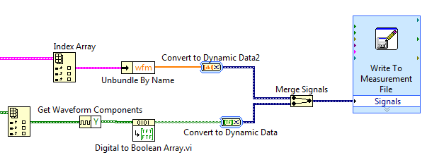
Save the digitizer and DIO waveforms in a single spreadsheet file
I use mixedsignalscopeusingtclk.vi attached data acquisition and want to acquire 4 channels of data. My system PXI-1042 PXI-5122 and PXI-6552, and I use 2-channel digitizer and 2 digital i/o channels. I'm using Labview 2010 SP1. The VI generated table 1 d of the cluster for an analog waveform and table 1 d of digital waveforms. How to save the two waveforms on a worksheet?
Hello
You can use a write file express VI measure. Note that this is the easiest but not the most effective way to write to a file.
Since you have the extraction screws inside loops, your output is a table 1 d of waveforms. You will need to obtain the wave form and convert it to a type that can read the express VI. If ungroup you the waveform and retrieve only the data and connect directly to the express VI, LabVIEW will automatically place a block of "Convert to Dynamic Data" online to make it compatible. This also applies when you connect the Boolean matrix at the entrance of signals express VI. And if you connect more than one signal to this entry, LabVIEW will automatically place a block of "merge signals."
If you reproduce the code below, you should be able to write both channels in the same measurement file. If you have more than one channel of each type, you can enter multiple items using the same table Index block and take them through the same process shown below.
I hope this helps.
-
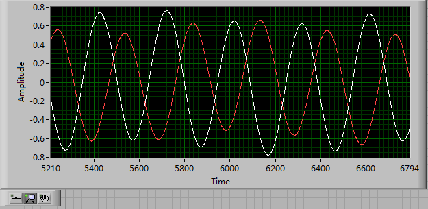
Distortion of the signal caused by the channels # sampled and sampling frequency
I am using an acquisition of data USB-6211 (250 ksps / s) and looking at the sample channels 3s 80kS. (Labview 2012)
When I taste one channel, it looks fine (1 Channel_Sampled First_250kS), but when I add another channel to be sampled, the signal is driven down and that it depends on which channel is sampled (2 channels (Different) _Sampled First_40kS and 2 Channels_Sampled First_30kS). Addition of channel 3, it pulls down even more. I also noticed that the sampling rate also distorts the signal the higher the sampling rate, the more the signal is driven down.
The acquisition of data IS sampling of signals "correctly" when I run my Labview VI my external hardware begins to read in correctly based on the distortion of the signal.
What is the cause and is there a way to fix this?
I have attached the waveform above captures and can post some if necessary.
Thanks in advance,
WBrenneman
That's exactly what ghosts means. The measurement signals later is affected by other signals. It happens usually if you have a high impedance input signal. Adding pads like you can help solve this problem by making the signal to a lower impedance.
Ghosting would probably look worse to the frequency sampling rates higher, just as you said that you had problems, as it provides less time between samples of the amplifier set new voltage level when the multiplexer allows to switch between input signals.
-
acquisition of wireless signals and record the signal as text at the same time for 5 minutes
Hello
I'm wireless ECG signal and the display in waveform graph. And at the same time, I need to save it as text for 5 minutes. The problem I faced is for record of the signal, I use scripture to the extent file that saves the file as text... but everything by saving the trace speed decreases.
I'm very new to labview so please can someone me if Miss me something in it... Please help...
Why people always post photos of their screws rather than the screws themselves or at least excerpts? We can't tell from the picture what Version of LabVIEW, you use (so if we post code, you will not be able to open it), and we can not 'play' with your code and try without, ourselves, by hand, trying to recreate your diagram (sometimes very small). Please, help us help you!
This is in any case helps to familiarize yourself with the design of producer/consumer model.
- Open LabVIEW.
- Click on 'File', choose 'new '.... "(no new VI), then (in models) producer/consumer Design Pattern (data).
- Study the model and adapt it to your problem.
The producer would be anything that generates data. Once you have the data, you put on the queue and send to the consumer for the entire treatment. The idea is that the producer has an inherent calendar that he must answer, otherwise you lose data points. The consumer, on the other hand, just need to follow 'more or less' (in fact, the queue may / will develop, if the amount of data is not megabytes, so the consumer can really be quite slow, if you usually want to consumers, on average, to be at least as fast as the producer).
Bob Schor
-
How to increase the power of the signal microsoft virtual wifi adapter
How to increase the power of the signal microsoft virtual wifi adapter? How change the virtual wifi for my external usb wireless adapter and make it work the same?
Hello
I suggest the following methods and check if it helps.
Method 01:10 tips to help improve your wireless network
http://www.Microsoft.com/athome/Setup/wirelesstips.aspx#fBid=poyhbeDlRAP
Method 2:
(a) plug your modem wireless on one of the USB ports on your laptop computer and if necessary, turn on the modem.
(b) right click on the "Network" icon in the lower right of the desktop and select "Connect to a network." Wireless modem will now be recognized as a network card.
(c) right click on the name of your wireless modem and choose "connect".
(d) enter the user name and password of the account that you put in place with the wireless modem provider.
(e) specify whether you want the wireless modem to automatically connect to Internet or not. You can choose to have the modem connects automatically, unless you are in a roaming area.
(f) press "Continue" to complete the configuration of the wireless modem and start using it as a wireless adapter.
-
my wireless adapter does not pick up all the signals... I don't know why... Please help!
I'm not sure why I can't my wireless dlink adapter cannot pick up all signals?
anyone enlighten us?Hello
1. what exactly happens when you try to connect to the Internet?
2. you get any error message?
3 have there been recent changes to the computer before the show?
I suggest you to try the steps mentioned in the link and check if this may help.
Method 1: Wi - Fi and in Windows network connection issues:
Check this link for more information:
Why can't I connect to the Internet?
http://Windows.Microsoft.com/en-us/Windows7/why-can-t-I-connect-to-the-InternetHope this information is useful.
-
Is it possible to plug a USB to my new iPad Pro, to transfer PDF files and some Jpeg files from the USB key with an adapter of lightning? If there is NO adapter, how can I get these files on the USB key and my iPad pro? I need these PDF files transferred my I touch pro. Any suggestions? Please
Thank you
Mike Tingey
The iPad does not support USB keys. There are some wireless flash drives that can be used, but not the classical records. I suggest you transfer files to a computer and their synchronization then back to the iPad via iTunes.
-
I have a good Wi - fi network at home using an Airport Extreme and Airport Express, but am moving my office on the other side of the House. The walls are plaster that inhibit the signal. Can I connect another Express to my extreme via an Ethernet cable for the office. I still maintain the wireless network. Thanks for your help.
Yes, it's the right way to do things.
Only the express will not extend the wireless... you create a wireless network of the same name and security settings... This is called roaming network.
-
Hello
We need power RF amplifier with a function generator to create plasma in an ion source. The signal pulse duration must be 1ms long, repeated twice per second.
Today, we work in the following way: we spend the RF with f0 (aprox 1,995 MHz) frequency. After 20, we send a trigger signal passing frequency f1 (aprox 2.005 MHz). We keep this frequency for the rest of the pulse. However, the plasma that we generate is not 'constant' or stable during the whole impulse. If we smoothly change the frequency during the pulse we could improve.
We would like to do: use the frequency sweep: rather than use this frequency hopping, we would like to move smoothly f0 f1 (frequency scanning). Then F1 to f2.
As we have a PXI for data analysis, we believe using the arbitrary function generator of NOR: 5406 of NEITHER allowing the frequency sweep. However, in the book loads, it is not very clear, and I have a few questions:
-We can create a "list of frequencies. In the site OR below, it shows that the "minimum of Step' is 1.28us, which would be ok for us (I understand that the"minimum duration of Step"is the minimum time between 2 frequencies). However, the manual of the device "NI PXI/PCI-5402/5406 specifications" said the frequency list has a time step of 1 ms to 21s. What is the good?
-It is also said that the "duration of minimum list" is 1 s. For us, need us a shorter list that 0.5 seconds (we need to repeat the same pulse twice per second.). Is it possible to do what we want?
-At the end of the day, we would like to implement a control loop which modifies the list of frequencies in real-time.
http://zone.NI.com/reference/en-XX/help/370524L-01/nisignal_generators_help/features_by_device_smc/
Thanks for your help.
Best regards
Jose.Hi Jose,
You're right about the inconsistencies of the documentation. The minimum step was of 1 ms, but was changed to 1.28 µs to driver version 2.6. The help document has been modified to reflect that, but the specifications were not. I'll make sure that attaches.
The length of the minimum list is not listed in the book loads, and the latest version of the help the signal generators OR (driver version 2.9) lists the minimum list than the 1 step length. Aid has changed to the driver version 2.6.1 to clarify that the 1s meant 1 step. I've attached a screenshot of the help of the most recent.
There is an example that is installed with the NOR-FGEN driver called "Fgen Sweep Generator.vi". I would recommend from this for your application.
I hope that some of the inconsistencies in our documentation brightened. Please let us know if you have any other questions.
Elizabeth K.
Generators of signal produced technical support engineer
-
Hello world!
First of all, I use a USRP as a transmitter to emit a sine wave (the signal is exp(j2*pi*f*t)), and then I use the external clock to synchronize the two USRPs (Ref as PPS in are connected to the clock) as receivers. Receivers are in sync, and they are at the same distance from the transmitter, I thought that the signal they receive should have a nearly the same phase. However, in practice, the phase shift is big enough, and this problem really confuses me.
It's the received signals of 2 receivers.
Yes. What you observe is expected.
Near the bottof of this document read the area 'alignment Phase vs Phase coherence '.
http://www.NI.com/white-paper/14311/en/
And also, for the alignment phase, see the following 'Angle of arrival detection with NI USRP '.
https://decibel.NI.com/content/docs/doc-25716
Erik
-
Hello
We use the DMM and SMU-6363 map to test a hardware device. We will also use a PXI-2530 b switching matrix. We will use the digital multimeter to perform the measurements of voltage, DC and AC, measurements of impedance (2-wire and 4-wire), frequency and waveform acquisition. Can the PXI-4071 left be 4 wire connected (black jacks taken connected and red connected) mode and still be used to perform all other measures (including 2 impedance of the cable). This would simplify the switch connections.
Current measures use the son + and LO, but the HI and S-can remain connected. The problem you are having is if you have an active device the digital multimeter and take you a 4-wire resistance and the measurement of voltage with all 4 wires connected and then change to a current... When you do this, short-circuit you the terminals of the DUT, on that you just take the measurement of the resistance. If the terminal HAD, say, a power supply 10V, then you have just shorted out. Of course, this isn't a problem if your Instrument is a passive device, or if you change just the unused two lead whenever there is an active device of low impedance.
If you want to make voltage, current and 4-wire resistance, you need all 4 wires. If you want to do the voltage and current, you will need 3 wires, but you could connect the s + Hi and then just do the two wires. I vote running every 4 son to your DUT for maximum flexibility.
2-wire resistance is a must if you are measuring resistance above 10 MOhm. Alternatively, you can use 4-wire for all measures.

Maybe you are looking for
-
Audio crackles occasionally on Satellite Pro C660 - 21 d
I just bought a new Satellite Pro C660 - 21(d), and the sound crackles sometimes without apparent reason. This occurs both when you use headphones or speakers to the laptop. Any advice would be greatly appreciated!
-
Hello everyone, I am totally new to this area. I'm having a problem with a card PCI-6503, which runs in a PC with W98. I instaled the driver NOR - DAQmx7.0 and I have developed a very simple application to test the sending of any signal by the ports
-
I can't open my webcam
-
DVD will not work, Audio CD works fine
Hi, people. Help please! I have a Dell OptiPlex 745 running Windows 7. I use this computer to the Church and have used it for about a year. When I tried to show a DVD he would not play it. The activity light would flash for about 20 seconds and nothi
-
Sync of Smartphones blackBerry with outlook 2007
I'm able to sync with Outlook 2007. If I add a number to my phone, it will be added to my contacts in outlook. However, this is only one way. If I add contacts in outlook (addresses, phone numbers or e-mail address) that they won't sync to my phon