DIO signal
Hello
I would check if my digital input will be created out of the mask as described in the Interface "Client", my problem that I can not see my DI on the chart.
I will be grateful if someone help me
Thanks in advance
My sincere regards
You have only 1 point. Of course, you won't see it. You must save your values of Y in a shift register and build your table. Or use a loop TO read X SAMPLES and then display the waveform.
Tags: NI Software
Similar Questions
-
How can I get the USB-Quad08 with Dasylab encoder channel data
Hello
I'm reading the pulse signal of USB-Quad08 with Dasylab V10, but every time I got the error message "this Committee has no meter 9513.
I have configured the jury with Instacal and the test hardware is ok. I used the module 'Entry meter' (Modules--> inputs / outputs--> MCC - DAQ--> Counter Input) to read the signal of the channel meter. "Entry 9513 counter" displayed and I na not change settings. After connecting a graphic recorder module I run the application. The error message appeared.
I noticed that USB-Quad08 Council has counter 9513. But why the error occurs? How can I get his channel encoder signal?
PS. I can get with Dasylab DIO signals, but I can't any signal with TracerDAQ, even I can't find USB-Quad08 in his list of DAQ devices.
Please contact Measurement Computing.
-
Hi all
I use the CARD of PROTOTYPING NI ELVIS for the next task. I want to design a test of ICS (IC) application by writing and reading the digital signals for each chip. For example, if a chip 7808 (Quad gate AND 2 entries) is tested, I would like to SEND the input signals to the pins 1, 2, 4, 5, 8, 9, 11, 12 and RECEIVE the output signals of pines 3, 6, 10, 13. However, if a chip 7411 (triple 3-input AND gate) is tested, I would like to SEND the input signals to the pins 1, 2, 3, 4, 5, 9, 10, 11, 13 and RECEIVE the output signals of pines 6, 8, 12. All the chips would have 16 pins, which means that I must control 14 digital lines because the power and mass pins do NOT change. In short, I have to be able to control two-way digital 14 so that I can specify which lines would be entered and lines of what would be output for each chip. I'm using LabVIEW 8.0 and the MAP of PROTOTYPING NI ELVIS could come from a lot that came out with the DI and DO the lines reversed since he is old enough.
So far, I couldn't work with the channel. If a set of OUTPUT DIGITAL lines 0:7 output become. However, if a set of DIGITAL INPUT lines 0:7 entry become as well. I thought that the latter would allow me to use the channel of DI, but it changes just the lines at the entrances. I already looked at examples of ELVIS in LabVIEW (i.e. write in Channel.vi of digging and reading to dig Channel.vi) and they work fine individually. However, when I copy the block diagram of a VI and paste it into the block diagram of another VI, he said that the resources that I am using are already used.
Is it possible to work with all 16 digital lines in both feel so that I can WRITE/read of the different signals for each chip? Is there a better way to approach this problem?
ANY HELP IS GREATLY APPRECIATED! Thank you...
You are right, that the PCI-MIO-16-1 has only 8 cards of DIO. It may be possible to create a front-end for multiplex your DIO signals, but it can be difficult to control that. If go you ahead and a new acquisition card, ensure that it has enough DIO lines
Chris K
-
Hi guys!
I'm working on a project where I want to control a motor dc with VirtualBench and LabView.
I have the engine connected to a H-Bridge motor, so I need to send 3 digital signals from the DIO VirtualBench to H-bridge.
With respect to management, I figured out, but now I need help to get a PWM signal to one of the DIO pins.
I can generate a PWM of the FGEN but do not know how to export to a DIO PIN.
I can also generate a PWM with the Express-> entry-> function Generate signal in Labview. But I get an error when you try to write this signal to pin.
Or is there a way smarter or easier?
Help, please!
/ Christian
The digital i/o pins are supported as the SPI, I2C, static DIO (timed by the software) and exports of MSO Trigger or FGEN signals start. There isn't any feature PWM/meter.
It is not a way to generate a PWM signal real on the DIO pins, nor can you give a digital waveform to dig write. From the FGEN might be your best option here.
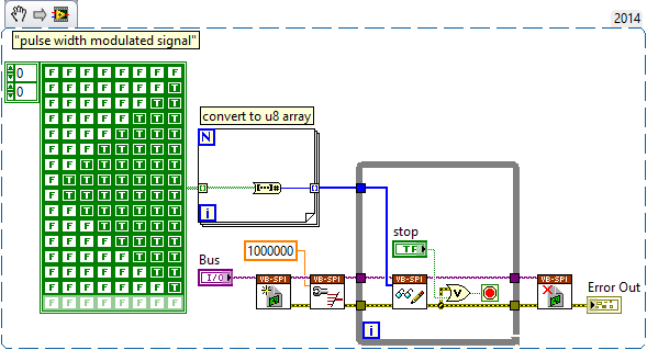
Another possibility might be to use (ab) the functionality of mastering of SPI. The following VI generates a modulated signal of pulse on dig/1 (MOSI) width. It will also generate signals on dig/0 (CLK) and dig/3 (CS), which may not be desirable, and you will have "gaps" between each call to read write of SPI.
-
How do I configure other digital ports except port 0 of daq 6351 acquisition of digital signals
Mr President.
I can acquire digital signals using 8 lines of port 0, but I have to get the waveform Digital 24-bit. So please tell me how to configure other DIO ports so that I acquired digital signals using these DIO line also
You should be able to create a task DAQmx to read Port0, Port1 Port2. When you read the DAQmx data, you must combine the port if necessary data table.
-
USB-6501 open collector signal generation
Hi all
I have carefully read the manual for this product, and I think that's what I'm looking for, but I was hoping just to get confirmation from someone who knows a bit more about it as I do. I have a stepper motor command that accepts control impulses. The differential voltage between the 2 input pins must be between 2.5 and 5 V DC. The control pulses can be RS422 or open collector type signals. The maximum heart rate is 250 kHz, pulse length must be greater than or equal to 2 microseconds and the time between two pulses must not be greater than 40 milliseconds. The engine must operate continuously for an extended period of time. Yet once, seeking confirmation that DIO can produce the signal I need. Thanks for any help.
It seems to me that this module can be adapted to be connected to your driver module. Output configuration you need is called "open-drain output" in the data sheet.
It is possible to drive a stepper motor driver with a generalist module e/s. But (in most cases), it is NOT possible to drive of a driver of motor Stepper with a constant pulse. You will need a rate of acceleration, i.e. it must increase the frequency of the pulses of zero to the desired speed of the engine.
-
HS tutorials - DIO / guides / examples? SMU-6544
Hi all
Is a repository for examples of HS-DIO VI available? Are there tutorials? I use a HS SMU-6544-RIO and want to use the generation of static and dynamic signals. So far, I've had a few basic features, but often I'm stuck. For the RIO or DAQ system it seems to be a lot more available resources. Also I couldn't find examples installed with HS-DIO drivers on the local computer. What is a good starting point? Any help is appreciated. Thank you!
Thank you for your patience. I talked to my friend of NOR who pointed me to the right direction.
Examples can be found here:
Open-> examples and navigate to hardware input and output->-> NOR-HSDIO modular instruments and devices
Source:
http://zone.NI.com/reference/en-XX/help/370520K-01/HSDIO/using_ni_hsdio_in_labview/
Hope this can help others in the future.
-
myRIO differential LVDS signaling
The myRIO can be configured to read or write songs by LVDS signaling?
Hi hkhalili,
The myRIO-1900 and myRIO-1950 only have single-ended DIO. Currently, if you have need of LVDS signaling and have a background in hardware design, the sbRIO-9651 has two LVDS input and output capacity. The sbRIO-9651 is a system on Module (SOM) and requires the development of a carrier Board of things like supplying electricity but also out the requested OID for your request.
The sbRIO-9651 is definitely a notch above in the flexibility and the configuratbility of a product of RIO, but it also comes with a learning curve and more steep development.
-
synchronization of signals HAVE, AO and c on 6014.
I want to achieve synchronization of signals, AO and c on 6014. Here's a 200077 road th sample clock error when I use a signal CO as the soure.
How can I solve the error?
Hi swinhaibo,
DIO in PCI-6014 lines are timed by the software, so you can connect to any clock signal to control. That's why you get an error. Unfortunately it is impossible around him other than the use of a different material.
-
Dear community,
I am trying to implement a background basket (software) PXI trigger on a chassis NI SMU-1082 with LabView 2015 (32-bit) running on an SMU-8135:
HS-DIO (SMU-6544) in slot 2,
-Acquisition of data (SMU-6363) into the Groove 4,
-Flex RIO (SMU-7962R + OR-6583) in the Groove 3.
The trigger schema is explained in the attached file ' LV-PXItrig-HSDIO-DAQ - overview.jpg ".
Scenario 1: written DAQ analog signal and sends signals trigger HS-DIO (software) through bottom of basket, after East of waveform of the complete signals to DAQ for acquisition.
Scenario 2: logical impulse on an external port HS-DIO triggers signals HS-DIO, after HS-DIO waveform is complete DAQ triggered for the acquisition of the ADC by the backplane.
In principle this breaks down to send a trigger of module A to B by PXI backplane. The SMU-1082 chassis has a bus trip with 8 lines (PXI_trigX, X = 0,..., 7) more a trigger in Star controlled the slot 2.
I've linked to implement a software trigger, but I can't access the refreshing resource and execution, see the attachment. Other ways of implementation including the DAQmx Terminal / routine disconnect Terminal have not worked for me either. I am aware about the connection of trigger using the node property VISA but I can't make a trigger.
Tips, comments or solutions are appreciated. Thank you!
For scenario 1, you want to trigger the HSDIO acquisition to begin as soon as the analog output DAQ starts? You can use
DAQmx Export Signalto send the trigger for the start of one of the lines from the Trig PXI backplane. Then, you need to configure your HSDIO acquisition to use a trigger digital beginning on the same line of trigger. Take a look at the example of the "Dynamic hardware generation start trigger" in the Finder of the example (help > find examples)For scenario 2, looks like you do a dynamic unit HSDIO generation when a digital trigger arrives on one of the PFI lines. Once the build is complete, you want to send a trigger for the DAQ hardware to begin sampling. If this is the case, you again use a trigger to start material in your task of NOR-HSDIO, as you did for scenario 1, but use external trig line as the source, rather than the bottom of basket. There is no case of material when the build is finished, but you can use a marker in script mode event instead. The example of the Generation with dynamic event marker' in the example Finder gives a good starting point for this type of operation. You'll want to set the output terminal for the event to be a line of backplane trig, and then tap the DAQmx to start on the same line trig trigger.
-
Hello friends, I have a question because I need to know what I need to buy the equipment.
I have a PCI1424 with a camera of DALSA CA - D1 256bis acquisition card, it really works very well and fast.
But I need to trigger the acquisition of images with an optical sensor activation.
I have the optical sensor, and I can install the IMAQ software to wait for a signal in the RTSI bus launch acquisition.
My question is:
Should what hardware I buy to connect the optical sensor (object in front of the sensor) signal into the computer?
I guess that some card DIO with RTSI bus, then I would plug the bus RTSI from the DIO card with the acquisition card RTSI bus to redirect the signal via the RTSI 1424 bus.
Should what hardware I buy that can redirect the signal from the sensor to the acquisition card 1424 RTSI bus?
Thanks to you all.
Frank
Hi frank_1424
In fact, you can trigger the acquisition in the way you describe without buying anything at all. 1424 has four lines of triggering on the connector 100-pin. If you look at page 3-2 of the Manual user , you can see that these are pins to 95-98. You should be able to relax out of these lines. If you do not want to dig your cable then yes a DIO card work for you. If you can give me a little more information, I can make a recommendation for you. What else could use you this card for in addition to any outbreak of your acquisition or is all that you can from the plug?
-
Why do I get error "20019 ADC conversion failed" with my pci-6143, when I try to use the DIO lines?
I am tyring to use one of the digital input lines on my PIC-6143 to go to the connection "enable" on the "write to file measure" vi. I have two cards PCI-6143 acquiring analog signals of 8 channels per step, plus I have a digital DAQ assistant to the sample line of DIO 2 on one of the cards. Normally I can start and stop recording using a signal of 5V to the DIO port several times until I get the error.
Strangely, when I use a simple Boolean "Record" button at the port of the 'writing on a file as' enable vi, I never get this ADC error no matter how many times I press the button.
I am including a screenshot of the error.
Thank you
Chris
Please ignore this message. The whole issue has been resolved by copying and pasting the VI in a new file in VI. The new file ran perfectly. Must have been a compilation of LabView or something error.
-
Generate a single pulse on several channels of an external trigger high-speed DIO
Hello
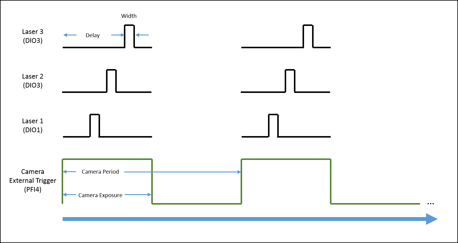
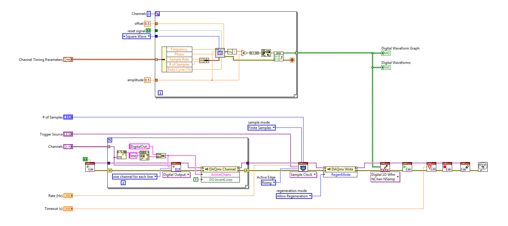
I'm trying to implement a system using a PCIe-6535 b connected to a high speed of SMB-2163 DIO. The system must be configured to work with a camera send a trigger (at the beginning of each show) to the PFI4 which in turn sends a single pulse on three digital output channels to lasers. Each output has its own specific deadline and the width. There is no counter on the SMB-2163, so I think I need to use Pulse Width Modulation (PWM). I saw this example and adapted to my system:
https://decibel.NI.com/content/docs/doc-8010
However, when the source to enter the DAQmx VI of sample clock is set to PFI4 (instead of the on-board clock) to receive input from the camera, changes in behaviour. The rate of sampling in the sample clock VI is ignored, and each element of the digital waveform is triggered. I need the sequence to complete each after trigger.
I am attaching a quick diagram of the sequence. Any suggestions on how I can get this kind of events triggered? (With the help of LabVIEW 2013)
Thank you
Mike
PLATES
The external signal must be configured as a trigger for digital startup rather than the sample clock. I do not think the 6535 redeclenchables supports digital output, so you don't have to restart the task after receipt of each trigger (something like this, however you can improve performance by committing to the task by using the task of control DAQmx before entering the loop).
Best regards
-
SBRIO DIO still available with 9693 mezzanine card?
Hello!
I intend to use a SBRIO (9626) and a map of mezzanine 9693 for plugging a 9853E module CAN.
However, I would also need interfacing #20 DIO, 4AI and 4AO. The signals will be be wired on J502 and J503 connectors.
Using 9693 mezzanine card, always will I be able to get/check status of DIOs/AIOs using the FPGA?
Hi zyl7,
The NOR sbRIO-9626 has only 4 asymmetrical on the J503 connector DIO lines as the sbRIO-9626 isn't a J502 connector. Using the 9693 OR prevents access to the CMR for anything other than the two C series connectors.
The J503 connector has 16 HAVE and AO 4 so that will work best for your needs that you can access IDC connectors and RMC connector at the same time in LabVIEW.
The isue with the sbRIO-9626 and the 9693 OR in your application, is that you will only access the DIO 4. If you need 20 DIO, you probably a DIO module in the second location of the 9693 OR add at least 16 DIO for your application. You can then use the 4 DIO embarked on the connector J503 IDC and the DIO on the C Series module to meet the needs of your application.
You could also add support on your daughter card circuits to multiplex your DIO 20 up to 4 lines DIO the sbRIO-9626 puts at your disposal. That depends entirely on the requirements of DIO, however.
-
entry of the FPGA 9402 trigger cRIO 9064 on DIO does not read
Hello
I have a cRIO 9064 using the Module C 9402 as a quick DIO in a SCTL. I use it in a (GPDD) digital delay pulse generator.
I've successfully the GPDD, triggered by a square wave generated internal, clocked at 1 MHz.
and I measure the pulse output perfect on an oscillascope.
My implementation is actually a clone of in: http://www.ni.com/example/31131/en/
However, when I try to trigger from an external 1 MHz, 6 Volt amplitude; duty_cycle 50%, square entering the DIO3 wave
There is no trigger, as seen on the Ticks_Between_Trig - which should be around 40, when it is correct release.
I used the method "Check status" to make sure that the 9402 is ready before the SCTL.
(Note: although it is labled Mod3 in the screenshot, it is actaully Mod1 and it simple namign incompatibility - which, once set doesn't change anything.)
I see not all digital HIGH when the input trigger control, what I do when you use the internal trigger.
The LED flashes, quite often even if actually at 1 MHz.
My question is what thing I must have the DIO 9402 read the input signal.
I followed the instructions here:
http://zone.NI.com/reference/en-XX/help/370984R-01/criodevicehelp/cRIO-9402/
but maybe I missed something.
Thank you
Michael
Resolved,
I had a bad input pulse generator which was flacky.
When I check the amplitude of the pulses on an oscilascope but a day later, when I corrected my code to include the ready method of Module C.
the amplitude of impulse was not working, but I've always tried to test with her.
Finally I double checked on the oscillascope again the trigger signal to find not suffecient.
Old eqiupment... then the warm-up does not.
Michael
Maybe you are looking for
-
I've been using browser Firefox 31 and now have a problem with the Extensions I can't remove enformation 1.1 0.95.19 by marketing company 1.1 improve navigation Version 27 that puts advertising on web pages. I used Firefox suggestion it goes then rea
-
High level VI execution control... What don't get me?
Hello all- I am writing an app that has controls on the front panel to access the calibration routines or collection of two subsets of channels on my data acquisition hardware (USB-6211)... called A Bank and Bank B. The problem is that, once I calle
-
2nd HARD drive internal for e9180f
Hi, I want to add a second internal hdd to my e9180f for the purpose of a backup drive. In my view, there is a spare Bay and a connection SATA spare available in the wardrobe, however there is no power cord. I notice that the power for the primary dr
-
Windows 7, problem driver ethernet... seriously need help!
Hi my names chris & My problem is that Windows 7 will not update my drivers ethernet and coprocessor. I do not have the cd that came with the office, and I don't know the name of the ethernet inbuild manufacturer. so I can't find the driver. It is a
-
Hello everyone around to answer this question?