Double plot mutual
Hi all
I'm doing a double reciprocal trace (Lopez Burk) for a study of the enzymatic activity. I've seen the plot on Excel but am not able to find
a similar solution in number. I tried to use the forecast function and also tried to get my bar tend to reach an estimate of values in my columns
in the negative numbers. No chance for many. How can I get the trendline to cross the y-axis? I don't know the technical steps to create a diagram.
I use numbers 3.6.1. and have a MacBook Pro from 2012.
Thanks for your help.
Kind regards
Jonelle

Maybe this will help you?

You can map all in simple X and Y, then get the best line made with a linear equation

Tags: iWork
Similar Questions
-
Lopez Burk field (Double reciprocal plot)
Hi all
I'm doing a double reciprocal plot of my data of the enzyme. I don't know how to go from a basic scatter chart plot to a double reciprocal plot.
I got my macbook in 2014 and the software is: OS X 10.9.5 (13F1603)
Thank you much in advance.
Kind regards
J

Hello j,
Weber State University in Ogden, Utah, of a set of instruction has do a lot of Lopez Burk in MS Excel, that you can find here. Formulas to convert the data pairs are reversed, and the graph itself is a scatterplot with a linear trend line 'better to' added. Creating a table similar in number should be pretty simple by following the instructions in Excel.
Kind regards
Barry
-
Graph plot legend colors Signal not updated when mixed with the property node
Hello
We try to put the colors of the trace of a graph of Mixed Signal using a property node. Although we can change the color of the data in the field correctly, the colours of the plot in the legend do not change until some apparently unrelated operator action is performed (for example, to resize the window or by double-clicking a field name). Waveform to XY charts don't seem to have this problem.
Anyone know a work around? I think I saw a similar topic on the forums earlier, but I'm sorry that I am unable to find it now

See attached vi.
Thank you
-john
I should probably have joined the last post of VI, but I have has been a thread of error between the two loops. I also deleted the text you had so I could see the I need to press the button.
-
Hello
I have 2 data in Labview, we're a couple time and Temperatura x time x. I want to put this in a report in a way I'm havo two pieces of information in the same chart, but without going through the plot. My idea is to make the bones of color temperature curve x acodding time change to the value of the couple at the same time. So when the torque curve will be red and when the couple is low the curve will be gree, and between the maximum and minimum values, I have a range of colours...
What is an easy way to do it?
Thnx
Hi Marcus,
You must double-click the 3D graph and check the legend box in the lower left corner of the dialog box to display the legend. After that, you can click on the 'Settings' button to the right of the "Legend" box to change the appearance of the legend.
Brad Turpin
Tiara Product Support Engineer
National Instruments
-
Problems with listbox - double click
Hello community,
I'm doing a program in which I'm building a dialog box by using the tab control and the user can double-click on one of the folders/files and this file must be read in the program and graphics need to be plotted.
To do this, I use a Boolean control, if I activate it, I call a tab control with a ListBox in which I use the function of list folder to view all the files/folders in the directory I put. I was able to get the double click event to work and give me the correct path to play the file using the function "read from the spreadsheet. The part of the plot is now over, but I have problems when I try to run the program.
The program was supposed to read the name of the cell that the user double click and only after that he reads the name I have change for a path access and then read. Which under its weight reads the file ListBox begins selected, as if I run the program once and double click on any file in the next run it will show the last selected file. The problem is that I am creating a node to invoke to reset the list box, but when I do this the program opens a dialog box to select the file to read.
So what I need is to figure out how to do the program only runs after the user to double-click a cell, should not read the file already selected in previous executions. But I don't know what to do. Can you help me please?
Thank you for your attention
Lucas
Faquim wrote:
Well, I'm pretty new to Labview, barely a month to use it. As English is not my first language, so I do not understand some of the terms you used, like "cut upwards" or "conditions of competition" or how to clear indicators in the beginning of the program?
...
The stacked sequence is to make actions happen in that order, that's how I learned. Local variables are also here because I don't know how to use the same variable twice or several times during a VI. Well, I'm still young enough for that.
Well, you break the data flow by copying in indicators invisible only to re-read a nanosecond later. Indicators are for the user, not to store data. If you eliminate the structure of the sequence, you can wire things together directly. Data flow automatically determines the exact execution order. No required sequence.
Faquim wrote:
The stacked sequence is to make actions happen in that order, that's how I learned. Local variables are also here because I don't know how to use the same variable twice or several times during a VI. Well, I'm still young enough for that.
indicators and variable local are NOT the 'variables', they are user interface elements.
Joined a quick attempt at a code cleanup.
All your operations of chain cable paths are still quite fragile. You should really exploited to the way datatypes. There are probably a few broken things because I can't test. However, it should give you some ideas.
-
remove the plot of graphic origin
Hey
I represent graphically a set of x and y values with the style line connected points. On the graph, the data are drawn, but there is also a line that goes back to (0,0). Is having graphs CVI anyway just my values and not connected to the original back? Thank you!
ICB does not connect the last point in a series of measures with the origin. When this usually happens, it means that you have stored your measurements in the larger tables that you actually need and you draw more points you have, so that the additional points with coordinates (0,0) are plotted.
For example, assuming you have these tables:
Double X [] = {1.0, 2.0, 3.0, 4.0, 5.0, 6.0, 7.0, 0.0, 0.0, 0.0, 0.0}
Double Y [] = {1.0, 2.0, 3.0, 4.0, 5.0, 5.0, 5.0, 0.0, 0.0, 0.0, 0.0}
If you draw only 7 steps you will have a regular route, if you draw steps 8 to 11, you will see the additional line initially.
I suggest you to set a breakpoint right before you PlotXY statement and examine your data tables with regard to the number of samples to draw.
-
Chart how many plots with wpf chart
This is probably a very basic question, but I can't understand how the chart more than a set of data with the chart WPF in VS2010. There is a DataSource property on the chart, but I don't see the same on each class of land. I can't find any documentation on the source property of the chart data. Can I pass an array of doubles and he plots very well but now I need to draw two sets of data. Can anyone help?
The
DataSourceproperty is documented in the how: map and graphic subject and on theGraphBaseclass (which is the type that defines the property). However, it seems that these issues do not directly address your question multiple plot; I put in a request to improve this.To answer your question, if you use
DataSourceto pass an array ofdoublevalues in a plot, you can use a collection to pass data to multiple locations (for example adouble[][], aList, or aObservableCollection).Otherwise, you could use the
Datacollection to provide each parcel with data; for example:graph.Data[0] = /* double[] for plot 0 */;
graph.Data[1] = /* double[] for plot 1 */;~ Paul
-
The plot required is a polar plot to draw the objectives is to identify a radar detector. I traced a XY Chart with coordinates obtained remotely and measures of angles.
I want to draw this positions X and Y in the polar plot. Source to the XY graph is a cluster of 2 elements while the connection to the Polar curve needs a picture 1 d of the cluster. The individual data are table 1 d of double and make a bundle does not solve the problem.
Please let me know how to build the polar plot with distance and angle data.
Kind regards
-
is it possible:
I have a chart, there several scales there... many on the left side of the graph and many on the right, I show only 2 at a time, it is essentially a plot of scale are double with y-selectable scales... I do using nodes of property and it works fine. I have drop down menus with plots different, and these plots will be display on the graph when selected... ok, here's my problem/question
is it possible to associate a conspiracy with a scale more there?
I need to associate patches with 2 ladders, one on the left and the other on the right side of my plots
because it is basically a graph with 2 drop down menus, drop-down menus has groups of plots in it... each 2 drop down menus contains the same plots and each is associated with either the y - balance right side or left side y-scales... This makes it possible for various different combinations of field vs trace on the graph... but being able to associate a conspiracy with two parties limit myself
for now, I can do
plot1 vs plot2
Plot3 vs plot4
but can not do
plot1 vs plot3... because I can't join plot3 y-scales on both sides of the graph
I hope this makes sense.
Thank you very much!
I don't know exactly what you're asking, but all the following statements are true. They answer your question?
- A field must always be linked to a single scale
- Many parcels can be related to a scale
- A parcel cannot be bound to a scale more
- A conspiracy may be visible, while its scale is invisible
- A conspiracy can be invisible while its scale is visible
- You can still have additional scales that are not related to plots
-
data is plotted on the graph of absolute time delay
Hi all
I'm plot data on a graph of absolute time and I find 2 hours difference between the data displayed by the debugger (left) and data on the graph (X - SCALE AUTO).
The time saved in ptTime, was acquired by using the function 'time' and the PC has Amsterdam, Berlin, Rome as time zone.
Here, under a screen shot that implemented the code, the debugger and the result.
The debugger is also showing the version in good time!
Can anyone suggest me how to process data in order to have the same result on the debugger window and on the graph?
A big thank you and best regards
Sergio
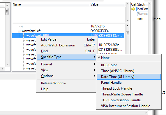
Question: in the CVI debugger show you, the time_t variable appears as a double, while its definition in 'time.h' is ' typedef unsigned int time_t; "so I am a little confused.
Response: I did something nonsense in this screenshot: I took a variable of type double (it happened to be a UIDateTime, actually) and configured the debugger to format as if it were a time_t variable. The formatted values that the debugger shows me, therefore, are not valid, of course. But I just wanted to show the time_t format, because it corresponds to what you have in your screenshot, and I was already suspicious that you use time_t variable to pass to the curve.
Furthermore, if you are not familiar with the way in which you can change the formatting in the debugger, this is how you do it:
Usually, the debugger can automatically pick the best format to use, based on the data type of the variable (for example, with variables of time_t). But in this case, what the debugger calls a variable "Date Time" is all just a double. The debugger cannot assume that you want to display all your double variables as a 'Date Time', and so you need to replace yourself.
Question: I was not able to find UIDateTime using the ICB type, this is the value returned by GetCurrentDateTime(double *)?
Response: There is really no such thing as a type of data "UIDateTime". I've been a bit remiss with my terminology. Unfortunately, when you're dealing with dates and hours, there are several possible representations of these quantities in the world of C, and it is important that you use the correct the intended variant you use for. In this case, the chart controls expect that you pass the time format used by the library of user interface, that is, one that is returned by the GetCurrentDateTime or MakeDateTime functions. The underlying C for this representation of the time data type is simply twice, and so it is not a good name to refer to it. That is why I used UIDateTime, but I should have been clearer than that.
Question: Y at - it a function to convert time_t values UIDateTime values
Response: Yes. You can use the functions of the programmer's Toolbox following two, in exactly this order:
CVIAbsoluteTimeFromCVIANSITime (time_t ansiTime, CVIAbsoluteTime * absTime);
CVIAbsoluteTimeToCVIUILTime (CVIAbsoluteTime absTime, double * uilTime);
-
Hi all
I am doing a project in LabWindows/CVI, where I have to post 16 tracks.
I did it with a StripChart, but I had to reboot with graphic, because I wanted to use the zoom feature.
Now, I can show my 16 tracks on the chart, but I have a problem with SetPlotAttribute. Here are some of my code (Simplified):
for (int k = 0; k)<16 ;="">
Plot (panelHandle, PANEL_GRAPH, time, k + 1, time + delaiCommande [i], k + 1, VAL_GREEN);
SetPlotAttribute (panelHandle, PANEL_GRAPH, intrigue, ATTR_LINE_STYLE, VAL_SOLID);
SetPlotAttribute (panelHandle, PANEL_GRAPH, plot, ATTR_PLOT_THICKNESS, 4);}
It compiles, but it crashes. I warnings: "incompatible pointer to integer conversion from ' int (int, int, double, double, double, double, int) __attribute__ ((stdcall))' to 'int' type parameter»
I'm sure that's no big deal, but I don't really know what to do now...
Thanks for any help!
Kind regards
jerome_gab.
Plot returns a handle thet you use during subsequent calls to set the attributes of the plot:
for(int k=0 ; k<16 ; k++){
        plotH = PlotLine (panelHandle, PANEL_GRAPH, tempsEcoule, k+1, tempsEcoule+delaiCommande[i], k+1, VAL_GREEN);
        SetPlotAttribute (panelHandle, PANEL_GRAPH, plotH, ATTR_LINE_STYLE, VAL_SOLID);
        SetPlotAttribute (panelHandle, PANEL_GRAPH, plotH, ATTR_PLOT_THICKNESS, 4);
}
You use a function instead, definition where the error you get.
-
How to plot the graph control scattergraph mulitple?
Hello
I have two double arrays declared and I'd draw x and y and x x. I can do one at a time, how can I add so that x, y and x, x points are displayed. I tried to use the plotXYmulitple command, but it requires a 2D array. What I need to convert my 2D table data or there is an easier option? any help would be greatly appreciated.
You are absolutely right! That's what happens you encode two o'clock in the morning. I'm writing my own solution below in the case where any other interested person. But you know it will be nice if you can make mulitple conspire like matlab function plot(x,y,x,y) etc.
Thanks again!
Kashif
double[] xValues = new double[5] { 1, 2, 3, 4, 5 }; double[] y1Values = new double[5] { 1, 2, 3, 4, 5 }; double[] y2Values = new double[5] { 1, 4, 9, 16, 25 }; scatterGraph1.DefaultDataOrientation = DataOrientation.DataInColumns; double[,] yValues = new double[xValues.Length, 2]; for (int i = 0; i < xValues.Length; i++) { yValues[i, 0] = y1Values[i]; yValues[i, 1] = y2Values[i]; } scatterGraph1.PlotXYMultiple(xValues,yValues); -
How to save the Agilent E4446A spectrum analyser plots
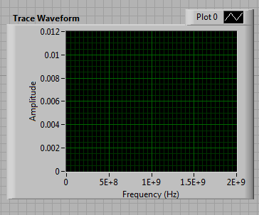
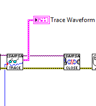
Hi all, I am a newbie to LabView. Now, I'm trying to store data (plots) of the Analyzer of spectrum of Agilent E4446A (SA). I was modifying the sample program (called Agilent PSA series ESA acquire Trace) of the driver of VISA. But I got stuck at the end of the program (I have attached the photos). When the SA have the plot of exact spectrum shown in the window "Waveform of the Trace" in the front panel, I don't know how to set up the program so that it stores the plot of the screen in format worksheet automatically. What I'm doing at the moment is manually, right-click in the waveform trace window and select "export". It's too slow to follow a few quick evolution results of SA. I was also trying to change the output of the function "Mark read" in his library of drivers. The production cluster (pink line) consists of the flow of three initial data (double) X, X increment (double) and Trace (table 1). I can not connect this cluster of data to 'Write in a file as' vi more, it's about the only life-saving method, that I worked with... I really want to learn how to automatically save the data in the format spreadsheet out of the plot.
Thanks a lot for your help!
-
How to customize the context menu in the legend of plotting the graph of wave?
I am currently on the creation of a simulation of various control loops as educational objectives. Here, I have a chart in waveform to different signals. Now my question, how to customize the context menu in the track of the Waveform graph legend => when I click on 'image' behind the Plotnames one menu to open options where you can customize the color etc. or plotwidth. But students should not have access to these settings. How can I change or disable this menu? The context menu for the waveform graph, I've already customized by right click on table of waveform-Advanced online-online menu, but for the legend of conspiracy, I have not found this setting...
Thanks for your answers... I tried different things, but I don't see a solution yet :-(
See you soon
DCP
Hi, STC,
There have been a number of suggestions for change or disable the table , right-click menu, but I see that this does not affect the context menu of legend , which is what you ask for help with.
To prevent completely the menu right-click to work, you must disable the chart control entirely. You can do this by double-clicking on the chart and select Advanced Options > active state > disabled. This will prevent the operator to be able to generate a menu right click on the chart control.
If however you still wanted the table, make a right click menu to work, but the legend made a right-click menu will be disabled, I see two options:
1. draw a classic decoration square on the legend and the transparent color. This will prevent the mouse clicks to achieve the legend, and transparent it will not interfere with your user interface appearance.
2 use a Structure of the event to capture the event filter Popup Menu of Activation? for the chart control. You can then use the Coords property to determine if the mouse is over the legend or not. If this is the case, send faithful away? right Terminal. It will refuse the context menu when the user clicks on the legend of the plot.
-
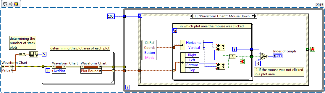
Determine the sub-plot clicked in a stacked chart
I would like to use the mouse upward (Mods
 double click) to detect what plot of a stacked graph of waveform area was clicked. It doesn't seem to be a property that actually said 'Clicked in field zone n '. A few properties that identify the coordinates compared to a reference which I can't find in the help of labView (of the locations stacked).
Is there a property or a common method of calculation of the selected plot area?
Thank you
XL600
AYanez wrote:
If I have understood correctly, this could help you.
It's more complicated than that. The limits of the land gives the value of the active parcel boundaries. Locations stacked, the default value is drawn 0. If this gives you the limits for the first plot area. You need get the number of plots and activate to get the values limits for each plot area. When the mouse is clicked you find if it coordinates are included in one of the plot area.
Here how to do it. I leave to the OP to change mouse double click event.
Ben64

Maybe you are looking for
-
Desktop PC: I think I have a virus which can do?
How will I know if I have a virus? What should I do? How can I prevent them in the future? Bill
-
What are some good resources for learning on the internet?
original title: use of the internet How could I make a positive use of the INTERNET?
-
Error code 8E5E05FA for update KB972270
The only "help" offered by Windows help had to accept the license. I did that and still nothing. The given next step is contacting this forum to see if someone else has thought of it.
-
CD or DVD drive is missing or is not recognized by Windows or other programs
How can I solve this problem withot having to reinstall the operating system?
-
Switch the Shift + del function with led?
When I press the button on a selected file he invites me to move to the trash. But generally, I want to delete it without moving it to the trash. To do this, press SHIFT + DELETE. I want to do with just the del key. I can't disable the Recycle Bi