Economy of periodic waveform
Hello
I'm working on the attached VI for the acquisition of the temperature. The program displays the data acquired on the two graphs in real-time and save it in a file when the user click on the dedicated button.
I want to add a feature which save the data in the file automatically every # measure (user-defined) and reset the graphics. I tried to do (see the lower right in the second while loop), but all previously recorded data is deleted and replaced. How can I write the new data after the old man? I don't know if I explained, I can give you more details if you need.
Thank you!
Your Subvi file writing have an entry called Append? By default, they are fake and will create a new file when you do not have a constant connected to it.
You must connect a real constant to these inputs, so it will add the new data in the file.
Is there a reason that you have two while loops? Why do you use of so many local variables? You can have race conditions seriouis past that might lead you to duplicate data, or data loss.
Tags: NI Software
Similar Questions
-
periodic waveform generation complex FPGA (PXI-7852R)
I would like to create a complex periodic wave (digital) with my PXI-7852R.
After checking the article here on the generation of periodic waveform with cRIO and then for a few hours trying to get this software to work on my fpga (PXI-7852R) I'm not much closer to making it a reality.
I bet that someone with more experience could some conversion not fast enough... Notice to lovers?
Thanks in advance!
-
How to get tilted periodic waveform in labVIEW?
Hello
I want to draw a waveform that has range of 0 to 360 and have a frequency of 50 Hz. the logic that I used in my code is like:
50 HZ = 0.02 seconds.
360/0.02 = 18000 (means multiply each sample to 18000 to get inclined wave that offers an amplitude in the range 0 to 360)
values go from 0 to 0.02, not accurate, and I multiply each step with 18000 to get the desired line.
1. take the current stage.
2. If step is > 0.02
then start from scratch
3. other (less then or equal to 0.02 seconds, then)
Multiply step with 18000
but I do not get the desired response. kindly help me, I'll be very grateful to you
Kind regards
Brassart ahmed
Why not use the function of the ramp signal? Check the range of signal generation.
Also, looks like you're wanting to generate an output signal. If so, you need to put your data in the buffer and to let the jury AO manage the timing of release. Windows has too much jitter timing to do what you want.
Mike...
-
I hope someone can point me in the right direction and also to clarify some concepts!
Background: I am currently using the box USB-6009 and labview on a laptop to output 2 analog waves. It acts as a waveform(0.5-2Hz) of speed (periodic) for an engine step by step (with a driver) to execute a loop of traffic, and the other waveform acts as a signal short 5V to trigger some imaging equipment. The ability to move or to delay the start time of the wave of 'trigger' compared to the waveform of speed in steps of hail (ms) became a requirement for my experiments. Given the time where the USB-6009 case, software based accuracy was not good enough because I need, and the way I wrote the VI limits my delay/travel at the speed of wave deltaT(30-40ms). I started to look at the USB - M series (portability is an obligation) since some have calendar based on the material, and I could send the signal to a buffer rather than iteratively having read every value of the wave in. It also seems that a digital short "pulse" works better than an analog wave form creating any. Where I ran into some confusion is to determine the requirements of a deterministic way sync the two. I am looking for new hardware. I started by looking at the box USB-6211. However, I ran across a few posts talking about the digital I/o correlated being required to perform vaguely similar configurations, which would require something more like the USB-6221. Since I have probably to the digital output to be on a time scale different analog output, is i/o digital correlated required? If not, would the 6211 work?
Just to be clear, I need the periodic waveform and relaxation to be constantly in phase (anywhere, 10 minutes to several hours). Then be able to move the pulse +/-1ms (minimum) and repeat. I can justify the most expensive device if necessary, but I don't want to get something I don't need.
I have attached a figure (not not to scale) of what I am after, in the likely event that my explanation was not too clear.
Thank you
Gabe
Hi Gabe,
The 6211 did not buffer IO digital as some of our other devices. However, there are two complete meters on the 6211 which can be used to perform a generation of pulses (pulse or continuous pulse train - you can output a pulse train using two counters finished). You can take a look at the section Applications of meter output x 621 manual for more information.
What it sounds like, the 6211 will do what you need for the following reasons:
1. the AO of the 6211 lines are buffered and can be clocked up to 250 kHz per channel (in contrast to the 6009 using AO NI by SW).
2 the 6211 counters can be used to generate two pulse based on a basis of time of 80 MHz (12.5 ns pulse width and resolution time). The 6009 does not output meter.
(a) if the two pulses must be on the same line, you must configure a task of generation of pulses finished' (this example uses two meters behind the scenes).
(b) if both impulses are on separate lines, then you can use a task to counter separated for each line with a different initial delay.
The 6211 does not supported clocked generation of digital signals (e.g. 100010101110100) but if you just need to generate impulses so that's precisely what the counters can be used to. I think that's where all the confusion, but seems like the generation of digital signals should not be necessary for your application. Trigger the counter outputs out of the trigger to start AO and adjusting the parameter 'Initial period' should give you what you are looking for. Don't forget to start the tasks of meter in the software before the tasks of the AO (if they are armed and ready to go before the start AO is sent).
I hope this helps, don't forget to post if you have any questions!
Best regards
-
Hello
I need to know about the economy of a waveform in JPEG or Excel or any other format.
If you want an image, then you can use the Get Image of a graph method and feed the image data to a JPEG file write VI.
If you want numeric data, you can use the write to VI file worksheet. This does not create an Excel file. It creates a text file with delimited columns, but you can open it with Excel. If you absolutely want to Excel so you use ActiveX. Examples are provided with LabVIEW, and more can be found in the thread Excel.
-
generation of functions to create channels of AO
I'm trying out a sinusoidal signal through a USB-6211 using this task Create Channel. I can't find a single example of using this function once the task has been created. All the 17 examples provided by OR use the adjustment of the tension of the AO create and must use an external function generator. Examples exist on how to use this thing? List of specifications of USB - 6211 BTW ' AO waveform modes:
"Non-periodic waveform.
"Periodic regeneration mode waveform of FIFO aboard"
'Regeneration of periodic signals of buffer host, including the dynamic update'
I don't know what the previous alternatives that seem to indicate that it is capable of producing waveforms, unlike other queries that came during my search for previous question.
Hi walter donovan,.
Only two devices support .vi DAQmx Create Channel (AO-FuncGen): NI ELVIS II and NI ELVIS II +, which have a function dedicated to the hardware level generator. You cannot use the channel type of the generation of AO functions with any other device. Sorry for the confusion.
Brad
-
That's what I'm trying to do. I have a file periodic_chan3.bin which is sampled values of three channels of periodic signals in interlaced format. The data is stored in binary format (long of floating point of the double procession) DBL and big-endian representation. I am reading the file and draw all the three waveforms on the graph of a waveform. The data has been saved from time zero, with a sampling frequency of 100 samples per second. Then I scale the x-axis of your waveform graph so it displays the time in seconds.
So I try, on the wave of the chart to create three sets of cursors and cursors to display the average value of each of the three waveforms. The color of the cursor Y for a given signal average must match the color of the display of the waveform on the chart. For example if the graph of the signal is displayed in red the cursor there shows the average of this signal must be red.
What happens when I do not open the file I see a white contour mesh a sine graph, a graphical square and sawtooth chart. I can't seem to trace the three waveforms seen clearly with the three above-mentioned distinct colors. I can't seem to sort correctly and represented as mentioned above.
I would also help with the calculation of the average or expected from each of the three periodic waveforms.
Attached are the files please help. Pgm4 is the VI, and periodic_chan3 contains the data that needs to be sorted. I'd be very happy if somene were able to fix the and submit the changes so I can see how it works. Thank you.
Edit: I get an error that says periodic_chan4.bin "is not a valid extension of an attachment" so I'm not able to uplad it. Is there a way to othe I could download it?
Xtasy26,
In your post you mention that you try to view 3 averages of waveform, however your code is showing that you are broadcast 4 values. This might be the reason why your getting the different forms of data. Instead of an array of all the waveforms 1, then a table of all 2 waveforms and a waveform table 3, you get a mix of all three in each of your waveforms.
To calculate a moving average or mean that it is actually an integrated in the example in BT sound finder called "running Avereage.vi calculation"
You can also view the attachment to see Multiple waveforms channel displayed on a single chart.
-
Why labview programmers use 10.1 the default frequency instead of a same 10.0 Hz?
It was an issue that was raised during the lab class and no one has an answer for. Any ideas?
I call it the wagon wheel effect.
In the old westerns, whenever a wagon with a Ferris wheel to rays rode by the camera, sometimes the wheel would look like it rolls slowly forward, sometimes slowly propagated backwards, sometimes it would look as if it was stopped.
It is a function of the frame rate of the camera over the period of the cycle of the spokes of the wheel. If we spoke (or more) offers exactly the right distance between a frame of the movie and the next, it would look like the wheel had not moved at all. If he moved a little further than the distance from rotation of we talked, it would look like it rolls slowly forward. If the cart is a little slower, then it would move only less than the distance of a spoke and he would look like the wheel rolls backward.
Same thing with having a periodic waveform (every bump of the sine wave is a spoke of the wheel) and a number of acquisition of samples and data rate equal to a whole number of this period (essentially the frame rate of the camera.) Wagon wheel always rolls forward. The sine wave is still oscillating. But according to the rate of acquisition compared to the wave sinusoidal frequency gives a different appearance to the appearance of this sine wave on the chart.
Experiment and give it a 9.9 Hz sinusoid, you will see that it seems to move backward.
So I think (and this is only a guess) is that whoever designed the express VI gave it a default value of 10.1 Hz to visually simulate on the graph of the sine wave motion.
It doesn't really matter what they chose by default as it is to you that the programmer LabVIEW to change this default setting (whether in the express VI or the wiring in a value) to something that makes sense for your application.
-
Data for the graph economy waveform
Hello
I'm trying to collect the data of temperature with the attached VI. Everything works fine until I open the exported file that contains only the last point of the chart. I already had this problem and I think that it is quite common, but I can't find how to solve it.
Thank you very much for your help!
Here's what you do. The central loop is where you get several waveforms. You want to write each waveform in the output file, which means you want the wave form to write to the worksheet in the Central loop. Look at its inputs and outputs - put three of them, the file Path/New path, add to the file? and the header? on the shift registers. Initialize (wants to say wire the register shift outside the While loop) the path of the file to "data\test" (as you've already done), with the new path towards the "output" Shift Register Terminal. False (the default) of thread to add to the file? and true (if you want headers) to headers? On the side of the "output" of these two SHIFT registers, wire to 'Add to the file?' "True" and "False" to "Headers?
For the first time you run the intermediate loop, the file will be opened in a new file (since add to the file? is false) and a possibly written header. All subsequent calls will add data in the same file (because you wired "True" to add to the file on the output terminal) and no header.
And to get rid of the unnecessary frame at the end – data flow will be responsible for sequencing.
Bob Schor
-
Add the delay between periods of a waveform
Hey all,.
I have used Labview to implement a generator of signals using the 'base FuncGen' VI, (WF-Gen.png) and I'm looking to make a change to the waveform. Currently I have my VI, set up to generate a square signal to a specified frequency and number of cycles. For example, a waveform of 1000 Hz for 1000 cycles would go for a second. My question is: how would I go put some points of zero V between each cycle? I've attached a picture to show what I mean (Signal.png).
Thank you.
GE
You need generate multiple signals and use Add a waveform.
-
generate the output waveform on 6259
Hello
I would like to generate signals of "simple" digital square output 3 6259 NI Board of Directors of 80 Hz.
Because of the wiring of my test tool driven 6259 Board, I can't use the output of the meter, but I need to plug into 3 output lines.
I re-used an existing vi and made by a subcontractor, but the generated waveform on my DUT does not have the expected frequencies (although it seems OK on the generated graph). Indeed, there are some forms of square waves, but not continuously. A sort of "pomade" and "elected" frequency does not match the measured frequency. If someone has an idea to help me, I have not experience on labview yet!
Thank you!
You have 4 unique digital States aimed at bike. Each cycle produces 1 full period of each of your square waves. If you want the output to 80 Hz, you must set the sample to run 4 * 80 = 320 Hz clock.
The other thing you see on the scope is that there are short bursts of pulses with parent long time between bursts. The calendar during the bursts are what control tasks. The time between bursts is caused by using the button "run continuously. Also that according to them, you complete vi almost immediately rather than waiting until they run awhile. Put an end to the execution of vi initiates self-cleaning of LabVIEW. These things represent the time brief burst and the ISH between bursts.
-Kevin P
-
waveform, with an average of results using labview to O-scope
Hello fellow engineers! I'm a first-yeargraduatestudent in CHEE at the University of Houston. Basically, I know nothing about labview. I am trying to program an application that looks like this - I collect a waveform of the signal of O-scope. This waveform does not change its characteristic shape. I need to find the wave form average of waveforms of N (100 for example). Thus, the slight changes (or noise) in the feature of form during the period mustbeaveraged out and I need to have a resultant waveform that represents the average waveform over a period. So, basically, I'm collecting the wave several times (for example 100) on a single period. The O-scope that I use now is Tektronix TDS 2024 B. It communicates with the computer via USB. The version of labview is 8.5. For now, I am able to communicate with the computer using our o-scope through labview. I already downloaded the driver of instruments of your Web site. It turns out that the program can give me only the average result I can get directly from o-scope manually. I need to have more say on average (100) using labview. I wrote a program that relies on the instrument driver that is downloaded on your website (for loop part is average, the waveform). The program that I modified and an instrument driver are attached. The program cannot be fully open, if the driver is not put in the right place in the labview (under lib inst.) When I run the program, the average waveform does not appear on the front panal and signal waveform file is not saved correctly. Is there someone can find where I did wrong and it develop for me? Because I barely know Labview, it will be even better if you can add an image or program that you have changed. I'm waiting for your creative ideas.
With the best regards,.
--
Weiye
-
Measure the period and the peak value at crest of a sine wave
Hello
I am new to Veristand and Labview and I was wondering if there is the possibility to do the following:
I would like to measure the period of a sine wave that I capture from analog input of my data acquisition (SMU-6363). Apart from that, I also want to measure the value of crete to crete (Vpp) of the sine wave.
I hope you can help out me.
Thank you.
If the sine wave is of significantly higher frequency than the primary control loop can run... The best way to do it would be to put the DAQ hardware in waveform input mode and use a custom device to read the waveform and perform analyses.
an example is here: requires some labview skills
\examples\NI VeriStand\Custom analysis Devices\waveform -
delay between the identical waveforms generated
Hello world. I want to generate tension by the use of the NI USB - 6353 X. When I tried to use the vi 'Voltage - finished output.vi' example, I realized that there is a period of time between two generated waveforms. It is an undesirable situation for our application. Why is this delay happens? How to generate at the same time?
VI of function generator based on there is an entry called Signal of Reset. Than the true value. What is happening is that your second wave comes to be a continuation of the first. As the first waveform settings say he needs a little more time, you get this time dead at the beginning of your second waveform.
-
tables of fixed size in FPGA compilation error - how to implement a waveform control in an FPGA?
Hello
After being stuck for two days, please let me briefly describe my project and the problem:
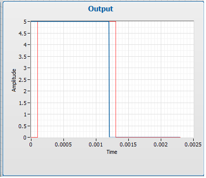
I want to use the cRIO FPGA for iterative control of waveforms. I want to capture a full period of the waveform, subtracting a reference waveform period and apply control algorithms on this. Subsequently the new period of correction must be sent again for the output module OR. If it does not work, the captured waveform will look like the one reference after several iterations.
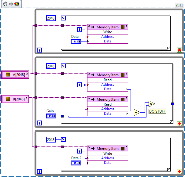
I am planing to create an array of size fixed for the capture and the reference waveform (each around 2,000 items for a given period). I use so 2 paintings of each elements of 2000. I use the function 'replace the subset of table' to update each element captured in the loop sampling and a feedback for each table node to keep in memory (I also tried shift registers, but then the berries do not have a fixed size any more and I can't start the compilation process).
If I try to compile the FPGA vi, I get the following error:
Details:
ERROR ortability:3 - Xilinx this application runs out of memory or met a memory conflict. Use of current memory is 4167696 KB. You can try to increase physical or virtual memory of your system. If you are using a Win32 system, you can increase your application from 2 GB to 3 GB memory using the 3 G switch in your boot.ini file. For more information, please visit Xilinx answer Record #14932. For technical support on this issue, you can open a WebCase with this project attached to http://www.xilinx.com/support.
"Synthesize - XST" process failedBefore I added berries to my code I could compile the FPGA without problems. So, it seems that the tables are too big for the FPGA. :-(
Therefore, I would like to ask if there is perhaps a better method to implement my problem in LabVIEW FPGA? How could avoid the tables to save my waveforms on a period?
Thanks a lot for your help in advance.
Best regards
Andreas
Unfortunately, the LabVIEW FPGA compiler cannot deduct stores shipped from berries (yet). When you create these two large paintings, you are creating essentially several registers very, very large. Just by looking at your picture, I guess that there are at least 4 copies of each of the tables.
You want to use LabVIEW FPGA memories instead. You can create memories outside the loop and then read/write them where you are currently referencing the berries. The only change that you really need to do is to break down your treatment in scalar operations. I have attached a simplified version of your plan, I hope it helps. Let us know if you have any other questions.
Maybe you are looking for
-
Non-administrator iTunes install
Hi all I am a network administrator and all our users have no administrator rights. Also, it is not possible to give them Admin rights. With the latest version of iTunes, the installation seems to require a little final configuration at the start of
-
Motorola Droid A855 device will not appear
When connecting to my computer via usb, it doesn't appear so I can browse the files.
-
Location of files that do not appear on the desktop
Yesterday I had problems connecting to my computer and when I finally got on my desktop items and favorites were missing. I did some work and saved a PDF file, but also an office document. Today, I have a lot on as usual and my old desktop items were
-
I upgraded my OS 9360 recently of OS 7.0 to v 7.1.0.336, 9.6.0.51 platform. Since the upgrade I have more the possibility to delete email messages on handheld only or on the server as well. I really enjoyed having the option to delete totally or just
-
solution to get the upgrade windows 7 to windows 8
Help me convert my windows7 home edition 64-bit windows 8 with any format or remove data from my laptop.