equation of solar cell
I implement the ideal mathematical model of a solar cell, with the equation of the solar cell as my base. It is to be part of a simulation of a PV system which includes a solar cell, an MPPT algorithm and a converter DC / DC. I am familiar with the toolkit OR for the characterization of cells PV I - V, and I use the * files lvm for voltage as input for my VI. However, it seems that I'm incorrect values in the XY graph, especially to the value axis. Can somebody proficient with PV cells take a look at my VI? I've included the VI and the * lvm file I used. Thanks in advance.
Have you tried to use the screws supplied by the box for tools without modification to compare the values you receive?
You receive the correct values when you manually enter the equation constants?
I found a tutorial that may be useful on the toolkit of I to V relating to photovoltaic cells.
http://zone.NI.com/DevZone/CDA/tut/p/ID/7230
I hope this helps!
Tags: NI Software
Similar Questions
-
Hello
IAM using assistant vision 8.5, labview 8.6, my requirement is
to find the cracks in the solar cell, can someone suggest me a solution, iam
sending the sample imageYour first task is to get a picture with a difference however between crack and surface of the 'good '. Did you fix an image? He was not part.
Depending on the construction of your solar cells and the step in the manufacturing process, that you're there, it might be interesting to explore what the IR lighting can do for you.
-
Feedback loops for the algorithm of peak power of solar cell
Hello. I have some experience with Labview but I am struggling with the structures and feedback. I have an instrument that defines a load power voltage and measures. It will be connected to a solar cell that has a peak power (see the trace on the photo). I need a simple program that will make the instrument to oscillate around the point of maximum power. He must set the voltage, power, add a voltage increase, measure power, then add or subtract the voltage according to the question of whether the power has increased or decreased from previous measure. I am attaching a schema. Start V and delta V will be given and fixed. I don't know how to implement with Labview code. Thanks for any help!
Hello
Search here for a simulated a simple peak loop
It allows to store the previous registry data at offset
e time delay without the processor and also to simulate the transfer of communication with instrument
concerning
Tinnitus
-
How to detect solar cells of the image
Hi all
Sorry, I posted this question on the other forum but received no response. Please help me in this task. Actually, trying to detect the solar cell off image and I thought of making a histogram of the image could be a first step, but I'm not the case now. Could you please provide me with an example of similar task which can be useful. Thank you
Concerning
Your original thread is not dead. I propose to close this thread and stuck with the original.
Hell! Meanwhile the other thread made reference to this. It seems that you now have to maintain two threads for a question...
-
How to open the solar kit in LabView 8.5
I'll build a test system of solar cell as a student project. I have access to labview 8.5 and I wan't to run the kit solar vi on the link below. The Toolbox is written for version 8.6 and does not open. Is there a way I can get a compatible version 8.5?
http://zone.NI.com/DevZone/CDA/EPD/p/ID/5918
Thank you if possible.
Hello
I saved all of these files in LabVIEW 8.5. Please let me know if everything works correctly.
-
Matrix of pixel intensity, success or failure
I'm having issues creating a VI that inspects the threatened pixtel in a given rectangle.
One of the problems I have is that there is a wire that appears black in SWIR imaging between solar cells (see attached photo). So I would need two rectangles to inspect the system, and I was not able to succeed in creating this program.
The second question, I have, I need a VI that controls the intensity of the pixel within the region of the specified rectangles. If there is a number of pixels which is not in this region (broken solar cell), assign an inspection of the failure. (see attachment).
Any help would be appreciated
Thank you
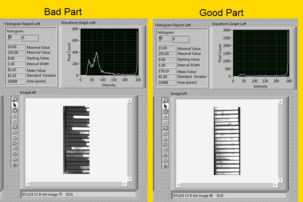
You should look into the Histogram tool. I have attached a VI for example. This does not solve your issue of KING, but it shows how to cut in the box as a rectangle.
Here is a picture of the results of the histogram. You can use the value "means" as a good/bad.
-
Hello everyone,
Can someone help to find a way of how any image to the right. If there is an image whose orientaion is completely out of phase comapred to reference the image so how to the right of the image. IMAQ rotation and symmetry IMAQ may do, but they work manually (you must change the angles yourself) but I want the labview to recognize the image and the right for me. Is this possible. ? I enclose my VI of base which consists only how directly the image and an image that may explain everything himself. Thanks for help
Best wishes
Lazer
Hello lazer.
Go to research on your forum of the previous messages, specifically one used:
The last program you posted ("detect the form 2.vi') sounds like you have an angle that comes out of your cluster of vi IMAQ detect forms . What you want to do to straighten a picture, is to take a reference to the desired shape, you make in this program, see its angle of offset vertical or horizontal, you also exit a function of unbundling by name and then apply this angle to rotate your image in the opposite direction to get it "right". I would take this angle and power in your function IMAQ turn you 'right of the image.vi' and see the results of it there.
-
measured LabVIEW frm data to record in a database
Hello again... I hope I am in the right forum to ask this... Im working on another project which requires me to use LabView software (apart from the other project on the welding process)...
This project is a solar cell of combat that will give me some current and voltage values according to some irradiation... So far, the measured data are presented and saved as excel file...
However, I need to do another concept of backup, to ensure that the measured data are saved in another way to ensure it is not lost... (I hope my explanation makes sense...:-s)...
My question is, is it possible to save the data measured in a LabView database?
Thank you...
Is there a way? Yes, but it requires you to create the database, set the tables in the database, and then download the data. There is no way of auto-la magic to convert Excel workbooks in a database. The database connectivity Toolkit (or LabSQL) is used to load the data into the database, but the database must be defined and created by you. If you don't know how to do this, you can either learn how do, or you can hire someone to do the work fo you.
Can do you it yourself? Perhaps. You really need to sit down with some primers on the databases first in order to understand the concept, purpose and uses of their. You must also decide what system of database to use. Using Microsoft Access, or something like SQL Server (or MySQL)? Anyway, that you would need to sit down with some tutorials.
-
Problem between Labview and Melanie 2602
Hello world
I think my question is a bit silly, but I really don't know what the problem is. I just want to read my current solar cell by changing the level of my blood to get an IV curve, which is normally pretty easy. So, I created a loop, where I increase my voltage step by step, and used a function named VI from Labview library that connects the Keithley and Labview together, "Keithley 2600 Series.lvlib: Source Level.vi. I start at 0 and increase by 0.01 volt each time. If I use execution of climax, I see clearly the value is correct, and if I go inside the SourceLevel VI, I clearly see the command string: "smub.source.levelv = 1.6," for example, if I want to put my voltage at 1.6V. The attached picture shows a part of my code.
Despite all this, it is clear that the Keithley does not react properly. It only works v of v 1V, 2V, 3V, etc... but never the values between. My IV curves are ok to read the Isc, but no VOCS. Never happened to any of you? I would be really happy to understand what I'm doing wrong, because it seems easy enough to solve. :/
Thank you very much!
It is quite difficult to debug a picture of a tiny part of the code.
But I'll take what I see. Your constant shows a 0.01 (comma). So I guess that you are in a country that uses a comma instead of a decimal point. I don't see what is happening inside the code Keithly, but I'll make an assumption that he made some conversions where it is expected that the comma is a period.
Look closely at the code Keithly and see if that explains it. Try to set your PC to use a period for the decimal point and try to re-run your code and see if it works better. It is possible that Keithly conversion uses a system, rather than setting using a decimal point, which is that your sentence says it's sending.
-
Hello
I need to make a program using Labview to obtain IV curves when the characterization of solar cells.
I have two engines that move in the direction of X and Y. choose a Y, the Xmotor moves a distance regulatory and stops at a time determined by a series of steps. What I need is to add the IV curve measurement in each of these steps. I Keithley2400 drivers, but I don't know if it would be better to use VISA, no idea how to do this? (it s the first time I will use resources VISA or similar
 )
)Thank you very much
You'll find plenty of screws in the related forums the 2400, swept some of them specifically for IV (with the drivers or VISA). I posted a piece of my code to scan IV here before... http://forums.NI.com/T5/instrument-control-GPIB-serial/how-do-I-set-a-source-current-and-measure-the...
I find using VISA provides a little more freedom in communication, but of course, it can lead to more errors.
-
How to provide a botton that takes a quick measure of the Isc and VOC?
Right now I have a program that allows to measure Voc, Isc and the efficiency of the solar cell. How to provide a botton that takes a quick measure of the Isc and VOC and displays the result next the botton? I want to do this because I want to know VOCS and SAIS before hand, so that I can set the amplitude of scanning. In addition, I also want to set the initial time in seconds. At present, the time is 3 seconds, I can't find where to put them, is 3 seconds by default.
Button not botton.
It will be similar to what you have already in your another thread.
Did you take the tutorials since then? I highly recommend you do.
LabVIEW Introduction course - 3 hours
LabVIEW Introduction course - 6 hours -
stop character during the IV sweep with keithley 2600
Hello.
I have a labview code to make the IV scans on a solar cell.
When I sweep V and I measure, it works great every time. Totally reproducible results.
When I I sweep and measure V, I get randomly 410 interrupts with the vi printbuffer() when playing back the results.
On the edge of survey error, I find the following details of the error.
WARNING 1073676293 was held at VISA read in KE26XX.lvlib
 rint Buffer.vi-> sweepiv_test_2600.vi
Possible reasons:
VISA: (Hex 0x3FFF0005) the termination character was read.
I disabled the stop character in him intialise Keithley 2600 vi, but the problem persists. The strange thing is that the code for the dredging of the V is exactly the same for I sweep (with obvious switches in the source and measurement).
It seems that the levels of measurement/source are eventually go out of scope and causing the weatherstripping to end at the beginning. But even when I force ranges to a level that would deny such a problem, I always get the error intermittently.
Any help would be greatly appreciated!
You can change a property for the stop character node and allow stop character in port VISA. It's under settings based on the Message. However, I have not work with GPIB to know how he handles things rather than serial ports. I don't have your Keithley VI to find out what's going on inside of them.
-
Why does my scan of source memory run twice? * Keithley 2400 * SCPI *.
The purpose of my VI is to perform a scan of the voltage across 6 distinct features of solar cells both in the dark State and with a light on. To do this, I'm first loading this scan on the Keithley 2400 and saving in the memory slot 1.
(Please ignore the _s. I needed to insert it so that the code would not be filled with emoticons...)
* RST
* CLS
* SRE 1
: _STAT:MEAS:ENAB 512
: _SOUR:CLE:AUTO ON
: _SOUR:FUNC VOLTS
: _SENS:CURR:_PROT 0.1
: _SENS:FUNC:CONC ON
: VOLT FORM: ELEM, CURR
: _SOUR:VOLT 0
: _SOUR:_DEL 0
: _SOUR:_SWE: SOUNDED BETTER
: _SOUR:VOLT:MODE SWE
: _SOUR:_SWE:_SPAC LIN
: _SOUR:VOLT:_STAR-0.5
: _SOUR:VOLT:_STOP 2
: _SOUR:_SWE:_POIN 100
: ARM: COUN 1
: TRIG: KEY
: TRIG: COUN 100
: TRAC: _POIN 100
: TRAC: FEED DIRECTION
: TRAC: FEED:CONT NEXT: _SOUR:MEM:_SAVE 1
So I call on this scan of source memory later in the program with these commands:
: _SOUR:MEM:_POIN 1
: _SOUR:MEM:_STAR 1: INIT
For some reason, the Keithley 2400 sweeps twice whenever I want to scan once. In other words, it makes dark 1 unit, then peripheral dark, 1 * delay *, light from the device 1 and then peripheral light 1...
I get only a data set each time, so I know not what scan data are reported. This is important because reads the scan sometimes did something for the solar cell, so I don't know if the data I collect is the first or the second sweep.
My VI and subVIs are attached, please take a look at them and give me your impressions.
Thank you
-
by the way of multiple charts for sub vi
Hello
I'm rather new to labview and could use some advice. My current project is using a loop for to create a chart for measurements of I to V of each sample of solar cells (each parcel is on a separate chart). Multiplexing is externally via labview control. I have a Subvi to show a sample report to the user before they are invited to save the report.
What would be the best way to transmit graphics data for 6 (or more) a slot - VI and then recreate the graphics in the Subvi? In my view, that a solution would be to use a shift to concate register bays of each series. Unfortunately, the size of the array is determined by the user (number of test on the graph points) running, and I don't know if I can separate the data correctly in the Subvi.
Another question would be to create an array of separate graphs (graph 1 element of table 1, etc.) using the group for each chart as an array element? I ask this because it seems that data within the Subvi separation would be easier with this method.
Thanks in advance for the help.
Without seeing the rest of your code, you can use a table of references or simply a table of waveforms. If you data for charts is not under the waveform you can simply create the type of waveform data using the wave to build function. See example attached to the approach of references.
pjr1121 wrote:
Do you know an example that illustrates the implementation of clusters in a table?I don't understand what you're asking here. Are you referring to an array of clusters? On the front panel or on the diagram block as a constant or the block diagram with respect to the construction of an array of bunches per program. For the façade, just place a table control and then drag a control of cluster within the table. Then place the elements of the cluster within the element of the cluster. For a constant block diagram, it is the same approach. To build programmatically, use Bundle or the boot by name then build Array or replace a subset of table depending on whether you are a new array of construction or replacement of an array element.
Did you have a LabVIEW tutorials? To learn more about LabVIEW, it is recommended that you go through the tutorials and look over the material in tutorials the NI Developer Zone Learning Center , which provides links to other materials and other. You can also take a course online for free.
-
I'm fighting in a tiff file import
Hello
I'm working on the solar cell as my final year project and I have to use LabVIEW. I need to import the image into the LabVIEW, are these tiff images. files. I use NI-IMAQ for it and made a VI and there is no error, but still it does not show the image on the screen of the control panel. I enclose my VI. Please help me in this matter.
Thank you
Concerning
Jawad
Dear Jawad.Zafar,
I hope you are well.
I took a look at your request and did a bit of work on your code so that it can display your image on the front panel.
There were only a few minor changes needed to get the code to work.
First, you use the incorrect "IMAQ Image and Info Vision reading" function. This product error-1074395989 (impossible to read).
You should only use the function 'IMAQ read the file '. It reads almost all types of image, such as PNG, TIFF files, JPEG etc.
Once I did this I found another error; error-1074396080 (invalid Image Type) on the 'Get Tetragon' function. This is because the "Image Type" control is set to "Grayscale (U8)". This type must match the type of image that is specified when the first "Create an Image" function Levels of gray (U16). Once I changed the correct type, the code executes without error.
I also suggest putting a STOP command while your loop, otherwise you will constantly produce the image on the front panel and will never be able to perform another treatment.
How to do this is use a function or and create a stop on the front panel control. This is connected to the terminal of the error of the while loop, change to a terminal of the judgment. This way if an error occurs or if you select the stop command, the program can be stopped.
I've included a modified copy of the code with this post.
I hope it's useful for you and the rest of your application right.
Kind regards
Maybe you are looking for
-
Trying to erase and reset my phone with no luck!
Trying to erase and reset my iPhone 5 s factory for a member of the family can use it. I'm going to... Settings > general > reset > erase content and settings But... He asked my password Apple ID through the next steps. I entered a million times (and
-
How can I stop my email to automatically open when I close the previous?
As soon as I clicked on what email to open first, once I chose to delete or move to or something else, the next e-mail opens automatically. I DON'T want my email opens automatically, I want to automatically return messages, but HOW? I use Windows 7
-
an easy way to reinstall the applications after recovery
Among the biggest problems that you encounter during the reinstall of Windows on your computer is to recover all of your commonly used programs. Ninite offers you an easy way to download a large number of the most commonly used applications. The si
-
WRT 330N V1 allows to reset the cable Modem
I have the problem that the (Wrt330N Version 1) router keeps resetting my Modem connection. I disabled the part wireless router and it doesn't happen too often. I tried not to get my money back no luck, I reinstalled the eprom support update told me
-
Scrolling problem when 3 container in QML text field
Hi all I extract some problems in QML. I put 3 textField but when focus arrives in 3 textfield at this time keyboard hide 3 textfield number so I was not able to display the text. I have attached the sample code.