Example rate vs clock rate cRIO
I try to get my head around the difference in sample rate vs clock rate in the cRIO so I can explain it correctly my engineers in optics.
I have a FPGA code that is just the Basic with e/s example. Modules 1, 2 and 3 are NOR-9201 with a sampling frequency of 2uSecs. The FPGA runs at 40 MHz or 25nSec/Cycle. Read in the documentation of the loop While takes at least 3 clock cycles. Estimate that other functions of the loop take about 7 clock cycles, the loop should run in 250nSec.
This is faster that the 9201 - can enjoy.
What does the FPGA? He expects the sample at the end? Takes the value of the previous sample? Do we get a partial sample?
Paul_Knight_Lockheed_Martin wrote:
He expects the sample at the end?
Yes - the loop runs in reality more slowly - he will meet at the level of the I/O node to the end of the sampling - time which is the sampling rate of any module is in the loop. For example, some modules analog high-resolution have read very slow time (like 52ms) then the loop will run at a rate of around 52ms (according to any other code you got in there).
If you have the e/s high-speed digital, you almost definitely want to put it in a different loop at any analogue I/O so it is not slowing down your loop.
I think that some modules are able to run in a single-cycle timed loop - in this case, the module will run in a single clock beat (for example 40 Mhz).
Tags: NI Software
Similar Questions
-
NEITHER 9234: sampling rate: cRIO, FPGA
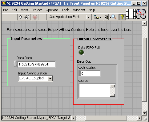
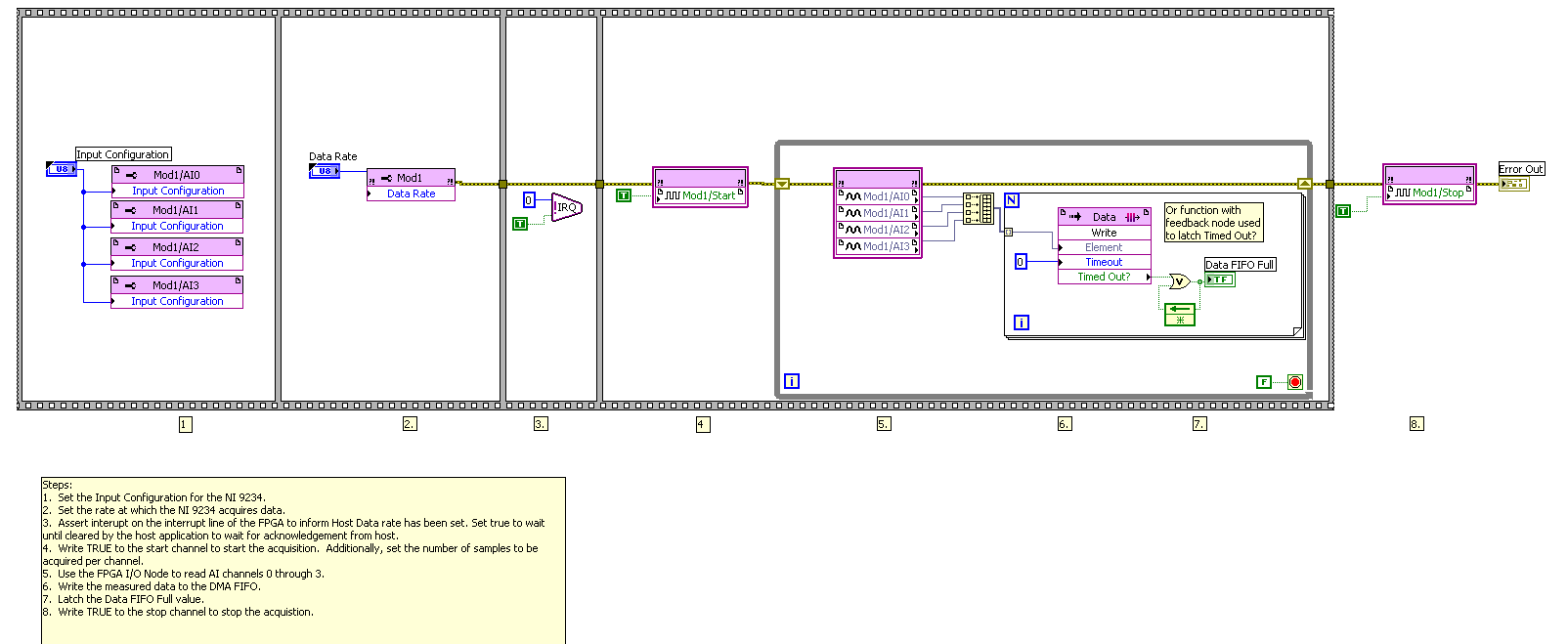
For the NI 9234 module, before Panel block diagram of my my cRIO FPGA code is as below.
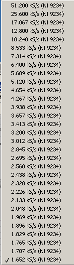
The sampling rate (speed) is selectable between certain values as shown below.
You have an idea how I can do the sample with a lower rate that is smaller than the option of character (1.652 ksps / s)?
Hi Cashany,
Take a look at this link. Page 16 describes the limitation that you run in. The main time base are divided essentially only toward down to some data because of the way the camera rates physically handles analog and digital filitering. So it's not really a way to divide the beyond that point.
-
Dear all,
Currently, I have a problem with NI MAX and my software that uses niimaqdx for camera firewire 1394.
I use HAMAMATSU C10600 (ORCA R2).
When I use the software HCImage that origin of the HAMAMATSU Corporation, I can get good pace which they spoke.
But in MAX, it does not work properly. For example, rate of rebar binning 2 x 2 is 15.6 Hz. But in MAX, it's only of 10 Hz. I tested binning settings. In Max, it can no more than 10 Hz.
And I tested all firewire cameras. It has the same problem.
But camera PCI card does not have this problem.
Please let me know the solution for this.Sincerely,
Taiyoon LeeHi Taiyoon,
First of all I suggest you check the camera settings in MAX to ensure that there is no maximum set of frame rates. In addition, you should check to ensure that the duration of exposure and shutter speeds are set so that the highest frame rate is possible. I recommend you take a look at this article in the knowledge base , which covers some troubleshooting operations when the camera acquisition rate is lower than expected.
Article:
"High refresh rate may not be achieved because the camera sends all executives. To achieve the maximum frame specified for these cameras, the shutter speed must be increased so that each image can be completed on time. It is an attribute that can be adjusted in Measurement & Automation Explorer (MAX). In addition, make sure that the camera is in the correct video mode. Several times for a camera reach its specified maximum frequency, it must be in Format 7 mode. »
I hope this helps!
-
Areas of clock in the FPGA examples
I was looking through some examples of LabVIEW FPGA and I fell on the example of Crossing Clock domains.
In this example, there are 4 screws; FIFOs.vi; Global Variables.vi; Local variables.VI; and Registers.vi. In each of these screws, there is a timed loop which runs at 160 MHz.
How is that possible? Since the clock on the FPGA is only 40 MHz. did I miss something?
On the FPGA target, you can right click on the clock of 40 MHz and create a derived clock which can be a multiple where for a fraction of the base clock (40 MHz).
160 MHz is a trivial example of 4 times the base clock.
-
Error getting started example 1 cRIO MDK
Hello
I have a problem with my MDK for the cRIO (April 2009).
I am connected to a 9074 with a 9263 to location 1.
In the manual page 5-6 o is a description of example 1. I opened the example and connected to the cRIO. (Screenshot60)
When I tried to launch the example I got an error message. (Screenshot57)
What I've done wrong?
Sven
Ok
I have soved the problem.
The examples are for 9101 Chassis und I used a 9074.
Now, I have copied the single VI in a new project, fixed nodes and it worked.
Sven
-
cRIO and synchronization with PC with 1588 on Ethernet card
Hi all
I want to synchronize my cRIO with my Windows 7 computer.
-Is it possible to apply the Protocol of 1588 in two materials using the PC as master clock and cRIO as slave?
-Where can I find examples?
The goal is to acquire temperatures via modules OR-9212 and cRIO to communicate to the PC by putting in place a lighter version of the JENA Protocol.
In the final architecture, I could have multiple cRIO.
Requirement:
Don't use NI 6682 H card or other
Can use the NI Sync module
Use on the borad ethernet card
PC running Windows 7 with LV 2013
cRIO-9067 under LV - RT 2015
Hello
This is a documentation on the implementation of the NTP Protocol on cRIO running Linux RT and the host computer with Windows
-Installing and configuring NTP on Linus RT
- How to configure a time server NTP on Windows
Adrien
-
I was in the process of switching to a MacBook pro-2016 Windows 10 and I think a number of things that I miss. For example, an analog clock. Apparently is not part of the operating system. I see there is for the purchase, but nothing of shareware that fits what I'm looking for, is there a solution?
The learning curve has improved, but the disappointment continues to grow.
You can choose one or more analog clocks to the dashboard.
-
clock calendar - digital output
Hi all!
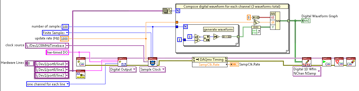
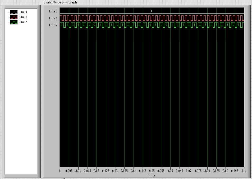
I need timing equipment impliment on a few digital output lines. That's what I have so far:
I didn't get an oscilloscope for her yet, but I'm fairly certain that it works. Please note that in this example, I use a PCI-6115. I have 2 questions:
(1) make what I do look reasonable at a quick glance?
(2) I'm kinda mistified by the entry of clock source to the example of the clock function. The analysis that I read just still confuses me. I understand that the clock is what dictates the sequence of material. I do not understand how to choose the appropriate clock source correctly. More specifically, in the above example, I've only had the program work when I chose "20MHzTimebase". What is c? Why this work?
When I try to select ' Dev1 / / SampleClock ", I get the following error:"attempted to perform a route when the source and destination are the same point."
When I try to select "Dev1/PFI0" or "RTSI0/DEV1", I get a timeout error in the wait_until_done.vi--> it does not appear that the waveforms are executed.
That means the PFI and RTSI acronym for, and why they appear as options when you select a source of the clock? Furthermore, why have they not worked as a clock source?
I would be very grateful to anyone who could clear things for me a little. Thank you!
Have you read the http://digital.ni.com/manuals.nsf/websearch/01C075FB9478F94A8625786A007435BA? manual The definition of PF and RTSI are here. They are designed using external clock signals. You have the choice of using the internal clocks of analog output (20 MHz) or external clocks. If you do not connect the RTSI bus or PF what, whether you have no clock so no data will be output. Selection of as source does not work because it is not a source. You provide a source for it.
-
excessive use of the memory of cRIO with without execution of the VI...
I have a cRIO-9073 which seems to work with very high memory use, even when no VI is actually being run. For example, if I format the cRIO, install the standard cRIO WHAT RTF S/W set (without the analytical engine) and then open Distributed System Manager OR I get 85% (!) memory usage. I did the format and reinstall to ensure doubly as no VI is running. I have used several other cRIOs, but I do not remember the operating system that requires this amount of memory.
Attached pictures of the s/w installed and distributed system manager.
When I'm not running my VI, I am of course short of memory.
HI Brad,
I have a 9073, and Yes, the standard operating system uses about 80-90% memory. You must choose the custom installation and strip off as much as possible. I have been using 9074 controllers since this experience. I hope that you can run your application by following these tips.
Good luck
Michael
-
Error 54 on udp multicast cRIO
I'm trying to get a data broadcasting cRIO-9075 on a network with UDP. I opened the UDP multicast examples and they work fine when I run them on my development computer. When I deploy and run the examples on the controller for cRIO, however, I get either "error 54 - network address is incorrect" if trying to use the example send/receive or perform UDP opened in read/write mode, or "Error 59 - the network is down, unreachable or has been reset" if I try to use just send UDP or UDP open write-only.
I use a valid multicast IP address located in the region of multicast (234.5.6.7 as in the example), have tried several ports, (0, 58432, 50001...) and we tried with my firewall disabled, connection internet Wi - Fi and bluetooth all disabled. The cRIO is connected directly to your PC via a cable network right development, although I'm sure that my network card is untangle break detection as the rest of the connection works fine.
Anyone have any ideas on how to debug this? I slightly touched a wall of bricks here, so any help would be greatly appreciated.
Hi Dan,.
I have a number of steps that you can try:
(1) would you be able to reformat the cRIO, then reinstall the software of MAX?
(2) try setting static IP address and choose an IP address.
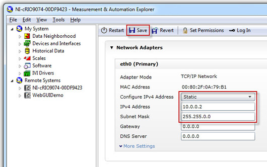
(3) then try to set the default Gateway to the IP address of the computer.
I look forward to hear from you,
-
How the PFI to go top-to-bottom with sample clock?
Hello world!
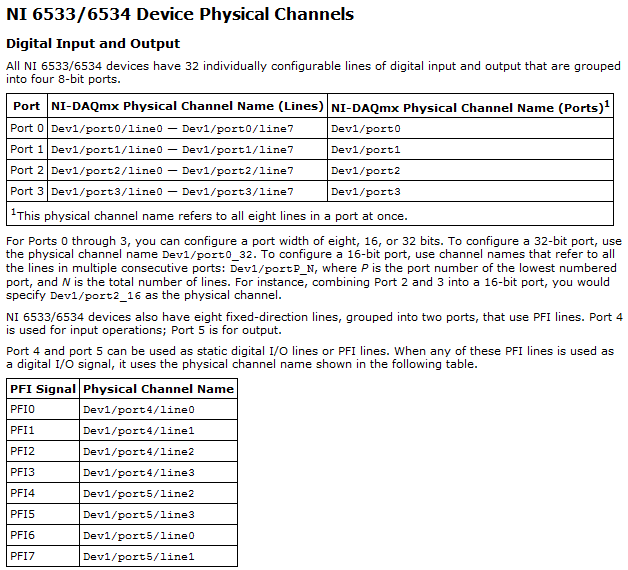
I am very new to LabView and I try to do something very simple in the NI PCI-6534 and still not get anywhere (or do not know if it is the limitation of the hardware)
My request is to acquire digital data of 2 channels (16-bit each) of our Board custom designed analog-to-digital.
So far, I am in a position to acquire a finite amount of sampling digital (say 100000) and using a trigger to start (PFI6) to start the acquisition of our custom card board. Just to let you know that I'm feeding the PCI-6534 an external clock of 20 MHz by PFI2.
However, I want to send a signal to trigger recognition (high/low-rising edge) to our personal advice, saying: he did the acquisition of 100000-sample.
My problem is that whenever I try to use the lines of PFI signal with an internal sample clock, I get an error saying that I can't use the PFI lines with any sample clock. But my goal is to use a rising edge (low-high) to trigger back.
So far, I can pull the PFI4 high and used a timer to make it low. But the resolution of the timer is milliseconds (software) range. I would like to have at least a few microseconds.
I also tried using implicit since manual said that it does not require any clock but still get no result. Also, I couldn't find an example of implied clock and don't know if PCI-6534 supports.
Note that I'm able to use the clock synchronization of sampling with other DIO (Port 0 to Port 3) lines and get the result I want. However, I would need to use all our custom Board 32 - DIO for analog-to-digital data lines. So, using the line of PFI laccuse is the only choice.
If you have ideas/pointers, please throw it at me, I'll try them. Thanks a lot for your help!

See you soon,.
Yaseen KhanHi ykhan,
After validation, I noticed that it will not really work for what you are trying to do. The PFI lines on your 6534 are I/O static only as shown in the DAQmx help.
You will be able to control these lines, but only with software timing. You should be able to call and argue by their physical channel name. I hope this helps!
Kind regards
-
Create a digital clock from 12 hours to animate CC in HTML5 Canvas
Hello
I have the AS3 code for a clock to 12 hours of work with a dynamic text field and I try to translate in HTML5. I found several examples of the clock in javascript code, but I can't translate it into a clock to work in CC to animate.
Can someone help me to translate this AS3 code working javascript/HTML5 to animate CC?
Add enter the event framework to the dynamic text field.
theTime.addEventListener (Event.ENTER_FRAME, showTime);
function showTime(event:Event):void {}
Create a new instance of the date class.
var myTime:Date = new Date();
This returns the seconds, minutes and hours.
var theSeconds = myTime.getSeconds ();
var theMinutes = myTime.getMinutes ();
var theHours = myTime.getHours ();
var ampm:String;
Display am/pm according to the current time.
If (theHours > = 12) {}
AMPM = 'H ';
} else {}
AMPM = "AM";
}
It subtracts 12 of the hour when it is higher at 13.
If (theHours > = 13) {}
theHours = theHours-12;
}
If (theHours == 0) {}
theHours = theHours + 12;
}
Adds "0" If there is only a single digit.
If (String (theHours) .length == 1) {}
theHours = '0' + theHours;
}
If (String (theMinutes) .length == 1) {}
theMinutes = '0' + theMinutes;
}
If (String (theSeconds) .length == 1) {}
theSeconds = '0' + theSeconds;
}
Displays the time in the dynamic text field.
"theTime.text = theHours +": "+ theMinutes +": "+ theSeconds +" "+ ampm;
}
var tl = this
createjs. Ticker.addEventListener ('tick', showTime);
function showTime (event) {}
Create a new instance of the date class.
var myTime = new Date();
This returns the seconds, minutes and hours.
var theSeconds = myTime.getSeconds ();
var theMinutes = myTime.getMinutes ();
var theHours = myTime.getHours ();
var ampm.
Display am/pm according to the current time.
If (theHours > = 12) {}
AMPM = 'H ';
} else {}
AMPM = "AM";
}
It subtracts 12 of the hour when it is higher at 13.
If (theHours > = 13) {}
theHours = theHours-12;
}
If (theHours == 0) {}
theHours = theHours + 12;
}
Adds "0" If there is only a single digit.
If (String (theHours) .length == 1) {}
theHours = '0' + theHours;
}
If (String (theMinutes) .length == 1) {}
theMinutes = '0' + theMinutes;
}
If (String (theSeconds) .length == 1) {}
theSeconds = '0' + theSeconds;
}
Displays the time in the dynamic text field.
"tl.theTime.text = theHours +": "+ theMinutes +": "+ theSeconds +" "+ ampm;
}
-
Redeclenchables buffered count task of edge
Hi all
I worked on 'Buffered Retriggerable counting task dashboard' on a single window input channel, let me describe what I want to achieve:
Create a CI to count the rising edges finished with the (for example external sample clock Dev1/di/SampleClock) at some rate of sampling and CI.edge.Term together in a PFI which is wired to another channel of digital input. In addition, I would like to define "start redeclenchables trigger" for this CI by another PFI line.
It turns out that I can put only 'arms start trigger' on this channel of entry of the counter, instead of "start trigger" since the 200452 error: attribute not supported in the context of task showed up at the beginning of digital edge trigger configuration. It seems that I can put only 'start redeclenchables trigger' on output special counter and use two counters to reach above, but I was wondering if there is a way to accomplish through single window. Any suggestion is appreciated.
Set the THIS ongoing task - it won't take samples when the task finished di which is actually the same thing as having a task over redeclenchables CI triggered.
If you want the count to reset each trigger, you could configure the entry as a Reset counter line well trigger.
Best regards
-
Sampling frequency for digital sampling (cDAQ-9172 & NI 9401)
Hello!
I have a cDAQ-9172 with NI 9401 C-series (digital) module. I would like to taste the digital inputs with a sampling frequency of e.g. 400 or 200 kHz. My problem is that I can only choose a clock 100kHzTimebase and therefore only get a sampling rate of 100 kHz. The 20MHzTimebase clock is too fast, as it gives me a sampling rate of 20 MHz). Is it possible to get a defined user e.g. 200 kHz sampling frequency, dividing for example down the clock of 20MHzTimebase?
Thank you! Last post and this article using the internal one or cDAQ chassis counters has solved my problem.
-
The honeypot trap vs reCaptcha
I think that reCaptcha is technically excellent, but from the point of view UI fail. Has anyone tried using a trap of honeypot instead of Captcha and reCaptcha? Could this work?
The trap of the honey pot
Malicious robots are full delicious field, so set up a "honeypot" field with hidden CSS which is invisible to users. You can set your validation fails when there is that anything that is entered in the field of honey pot.
This method completely removes the friction of the CAPTCHA method - unless the user has disabled CSS, or use a browser that auto-remplit common fields. This can be a high percentage, so consider using a field that is rarely asked by other sites, such as the zone, but something the bots might recognize.
Just to add to my single face debate... CAPTCHA has an impact on the conversion rate? A study suggests for this... http://www.SEOmoz.org/blog/CAPTCHAs-affect-on-conversion-rates
{module_ccsecurity}
Some bugs right now to be fixed soon, but all new forms, you will see this added. Basically, it's honey pot and a little more.
You just need to add it to any old web forms.
AS a recent spam score - it is partially manual process and honeypot Captcha or anything like it either won't work around.
Conversion rate of captcha is greatly based on how you implement it. ReCAPTCHA is a low conversion for example rate because it's not great to look at and the image that it makes is small enough.
Maybe you are looking for
-
When open my pc it there some type 'check on NTFS file system.
When open my pc it there some type 'check on NTFS file system.
-
Color LaserJet CP1025nw: printer does not print after changing cartridges
I just inserted cartridges M, Y and C in my printer. They are official cartridges 126 a. I followed all the instructions (shook gently, removed the orange protective cover and pulled the Ribbon out). I inserted one at a time, waiting after each in
-
window does not pass the validation Build 6002
I have what is clearly a common problem. My 4 year old computer with Windows Vista Home Premium Dell started man me messages that the installed version of Windows is not valid. Here's what I did to try to find the cause. Please tell me how to solv
-
How can I reset my computer back to factory setting. I have just the Basic windows 7
my computer is slow, and I just want to delete everything off and reset back to factory. I'm still all disks that came with it
-
How to set this query, please suggest me.
Under query returns the rows 50 million but taking 6 minutes to complete:Select / * + full (udf) full (udm) full (ul) full (d) full (hw) PARALLEL (udf 16) PARALLEL (udm 16) PARALLEL (ul 16) PARALLEL (d 16) PARALLEL (hw 16) * /.SEPARATE d.dmdunit, d.l