explain DAQmx WARNING 200035 conversion rates lower clock rate minimum?
I'm sampling of data at 1 kHz on 3 channels using DAQmx read. The DAQmx Read function returns a warning that:
"Specified clock rate is lower than the minimum conversion rate of the ADC." Your data may be invalid.
The material I have is a Multifunction PCI-6115 data acquisition of NOR. If I am interested in signal above 100 Hz can I safely ignore this warning or what I taste to 50 kHz and then have labview re - sample data at 1 kHz?
Hi, according to the specifications you are limited by a minimum of 20 kS/s sampling rate. anything weaker that should give you the same error, because this is a physical limitation of the card is using the internal sample clock.
Tags: NI Software
Similar Questions
-
CVI2013: WARNING: implicit conversion changes signedness: "long" to "int".
What is Clang was trying to say with this warning?
int f( void )
{
  int i1 = 4;

  int i2 = 1l << ( i1 - 1 );
  //       ^^  warning: implicit conversion changes signedness: 'long' to 'int' [-Wsign-conversion]

  return i2;
}
Hello CVI - User!
The explanation is quite technical...
The result type of the expression of SHIFT is "signed for a long time." The target type of the initialization is "signed int". Clang injects an implicit "signed long" conversion to "signed int" and check the different properties of the conversion.
In particular, clang tests if the sign of the value can change during the conversion. For this test, clang calculates the range of 'values' of the source 1 L< (i1="" -="" 1)'="" and="" the="" "value="" range"="" of="" the="" target="" 'int="" i2'.="" the="" warning="" indicates="" that="" the="" signs="" of="" the="" source="" and="" target="" ranges="" do="" not="">
The range of values of the source depends on the expression 1 L< (i1="" -="" 1)'="" and="" here="" clang="" is="" applying="" a="" special="">
    [excerpt from GetExprRange in the clang 2.9 source code]

    // Left shift gets black-listed based on a judgement call.
    // ...except that we want to treat '1 << (blah)' as logically
    // positive.  It's an important idiom.
Therefore the range of values of source is: wide, 32-bit positive.
The range of values of the target depends on the type of "i2" and that's the range of default values for "signed int": 32 - bit wide, positive or negative.
In other words: 1 L< (i1="" -="" 1)'="" is="" considered="" positive="" (unsigned)="" and="" it="" is="" converted="" to="" a="" signed="">
Note that this is really a special case and that you do not get the warning for other values:
int i2 = 2l << ( i1 - 1 ); //no warning
Unfortunately, I can not explain why clang didn't just compare the source and target types, it calculates the ranges of values and why 1< (blah)'="" is="" treated="" specially.="" i="" don't="">
Peter
-
Type of Conversion rate by default FAH
Hi all
FAH, you can assign the source of the 'Type of default Conversion rate' system for the accounting attribute "type of conversion rate. Great! But what type of rate if it picks up, where you set a default rate type?
Thank you
AbeAbe,
I doubt it was coded correctly.
You might get an error when using this source.
Please check with the help of the Oracle, if you are facing a problem.By
VAMSi -
data form for the opening of the conversion rate
Hello
I am trying to create a data form for entry of conversion rates. For example in the given line below, I want to create a data form to convert USD to euro and I want to enter into 1.05742 via the data form. I do not know how to select USD and EUR custom 1 and custom 2 members. where can I see this option?
Actual spending; 2005; January; Periodic report; [None]; [None]; AverageRate; [ICP no]; USD; EUR; [None]; [None]; 1.05742
I'm new to HFM and any help will be appreciated.
Thank youThis looks good to me. C1 will be USD and C2 will be EUR entity will be [none]. Choose USD and EUR in C1 and C2, make sure to change the 'Selector' drop-down list on the form of "currency".
-
Conversion rates for simultaneous data acquisition
I use a Mech multifunction data acquisition. / s/SMU-6366. The maximum sampling frequency for the analog inputs is 2 MHz. Is the time of actual conversion of CDA always 0.5µs, or t - it change with the evolution of the sampling frequency? Can I set the time of the conversion? Reading, looks with peripheral multiplex, you can set convert it clock and the sample separately clock. What is with simultaneous data acquisition?
Hi Daniel K..
It is a big question. I wonder if you get any errant behaviour - your card is not up samples as you hope?
Here is some information that might help you:
Wikipedia: successive approximations ADC
I'm not sure exactly what happens, but dare a guess time digitizing ADC does not vary with the frequency of sampling. And it will also be more than 0.5 US - it is more than likely faster than that.
I hope this helps. Good luck with your application!
-
The most effective way to log data and read simultaneously (DAQmx, PDM) high data rates
Hello
I want to acquire the data of several Modules cDAQ using several chassis to
high data rates (100 k samples per second if possible). Let's say the measurement time is 10 minutes and we got a large number of channels (40 for example). The measured data is written to a PDM file. I guess, the memory or the HARD disk speed is the limits. For the user, there must be a possibility to view the selection of channels in a graph during the measurement.My question: what is the best and most effective way to save and read data at the same time?
First of all, I use an architecture of producer-consumer and I don't want to write and display the data in the same loop. I expect two possibilities:
[1] to use the 'DAQmx configure logging.vi' with the operation 'journal and read' to write the data to a PDM file. To display the data in a second loop, I would create a DVR samples documented and 'sent' the DVR for the second loop, where the data will be displayed in a graph (data value reference). This method has the disadvantage that the data of all channels is copied into memory. Correct me if I'm wrong.
[2] use 'DAQmx configure logging.vi', but only with the "journal" operation to write the data to a PDM file. To view the selected data, I had read a number of samples of the TDMS file in the second loop (I'm currently writing the TDMS file). In this case, I have only one copy data from the selected channels (not), but there will be more HARD drive accesses necessary.
What is the most effective and efficient solution in this case?
Are there ways to connect and read data with high frequencies of sampling?
Thank you for your help.
You say that the measurement time is 10 minutes. If you have 40 channels and you enjoy all CHs at 100 kHz, it is quite a number of values.
In this case, I always try to approach under the conditions of use. If a measure is only 10 minutes, I just connect all PDM data and create a graphic module that could be in the same loop of consumers where connect you the data. You can always work on the raw data files big offline afterwards, the extraction of all the information you need (have a look at the product called NI DIAdem: http://www.ni.com/diadem/)
The main issue is that the user needs to see in the graph (or perhaps a chart can be useful too). Lets say that the graph is 1024 pixels wide. It makes no sense to show multiple data to 1024 points, Yes? Every second will produce you 100 data points k per channel. What is the useful information, which should see your username? It depends on the application. In similar cases, I usually use some kind of data reduction method: I use a moving average (Point by point Mean.VI for example) with a size of the interval of 100. This way you get 100 data points of 1000 per channel every second. If you feed your graph every second with these average values, it will be able to data points in 1024 of the store (as a default) by channel (curve), which is a little more than 10 minutes, so that the user will see the entire measurement.
So it depends on the frequency at which you send data to the consumer. For example, collect you values 1024 by iteration of the producer and send it to the consumer. Here you can make a normal means calc or a bearing (according to your needs) and he draw a graphic. This way your chart will display only the values of the last 10 seconds...
Once I programmed some kind of module where I use a chart and not a graph, and the user can specify the interval of the absolute timestamp that is traced. If the data size is larger than the size of the chart in pixels, the module performs an average calculation in order to reduce the number of data points. Of course, if you need to see the raw data, you can specify an interval that is small. It all depends on how you program zoom functions, etc... In my case I hade a rate of 1 Hz, so I just kept all data in RAM limiting the berries to keep 24 hours of data, so that technicians could monitor the system. In your case, given the enormous amount of data, only a file read/write approach can work, if you really need access to all of the RAW data on the fly. But I hope that the values of working capital means will be enough?
-
analog parallel DAQmx reads at different rates of acquisition
I'm running two 9172 chassis with a total of 11 modules. I have two 9217 modules for reading RTDs and a 9205 for sensors of reading level. I've set up three spots, one for each module.
If I do a task sheet and place DAQmx Read in a loop, I can read all the data without problem, but the three tasks take 4.59 seconds per iteration (reading the RTD is seems to be slower). I need to update the level readings more Rapids, but if I do two parallel loops, try to read the RTD in a loop (two tasks) and the level in its own loop sensors I get an error that the resource is not available - apparently only one instance of DAQmx Read can be called both.
Is there a work around for this?thanx
lmd2Larry,
Your problems are all related to the task that is described in the manual DAQmx State model. Each 9172 chassis can have 1 HAVE task that runs at a given time. If you try to start a second task, you will get an error. When you use the loop FOR your code is starting and collapses of each task in order that takes a lot of time and explains the 4.59 seconds. Ideal for config and start tasks in an init State and then begins to acquire data. The only thing left to do is to release the input/output by stopping and disabling tasks when you did.
One way to solve this problem would be to install two RTD modules in a single chassis and all 9205 modules in other chassis. Another way would be to oversample of RTD and process the additional data later.
-
How can I stop the warning message to appear low cartridge.
Checking the box "in the future do not show this" isn't making the messages stop.
How to overcome this please?
Thanks for this old_geekster.
Unfortunately, it turns out that the techo that installed the machine only gave me the drivers, as it claims that the HP programs were too extravagant large! So, I do not have a file of program of HP and therefore no Toolbox!
Guess I'll have to put up with excessive compensation warning messages until I have empty cartridges...
Thanks for trying to help.
Rgds, Norm
-
What is the difference between 'spot' and 'corporate' of the conversion rate
Hi all.
I'm really confused about this.
can someone give an example.Hello
Please see if (Note: 123542,1 - rate frequently asked Questions) help.
Kind regards
Hussein -
DV6 6c65se: hp pavilion dv6 6c65se RAM update more low-speed clock frequency
Hi I dedided to chenage my original RAM memory to a
Corsair CMSX8GX3M2A1600C9 NB Vengeance 8 GB (2x4gb) 1600 MHz CL9 DDR3 SO-DIMM two memory Module Kit Performance
When I changed to RAMto a new and restart a system, I was surprised the classification System went down from 7.6 to 7.4 could someone explain to me why this happened if the old RAM was unbraned in trouble from China? Why my new performance as Corsair is defined by the hardware to work on the low clock speed, also is there nothing in the BIOS to change the clock speed of RAm etc.
Could someone help me in this regard?
Thank you
Hello:
I can't tell you why the performance of WEI memory went down, but he certainly wouldn't.
The faster the memory will run in your computer laptop is 1333 MHz, because it is the fastest speed of the processor i7-2670QM FSB can run to, so installation PC3-12800 (1600) memory provides no advantage.
The original memory regardless who did, should have been 1333 MHz.
You need a PC with an Intel 7 series chipset and the 3rd generation of processor core to memory to operate at its rated 1600 MHz.
-
How to adjust the power of the low-battery warning sounds options?
Original title: WHEN the RECHARGE PORTABLE IT beeps AND I can't do it; HOW can ME to the MUSIC, I turn OFF THE BEEP?
OK SO WHEN MY DOUGH IS LOW, I THE BRANCH AND IT SOUNDS REALLY LOUD, I LISTEN TO MUSIC OR WATCH VIDEOS SOUND RS FORT BC AND A BIT BORING! HELP PLZ
Hello
Here are several methods.
Double click on the speaker near right lower clock - mix - MUTE Windows sounds or lower the slider
all the way.Control Panel - Power Options - click on change Plan settings for the offender to power you use and want
Change - change Advanced Power Options - battery - defined as you wish.Control Panel - sounds - warning of low battery - you can set that None
Also check the critical battery alarmI hope this helps.
Rob Brown - MS MVP - Windows Desktop Experience: Bike - Mark Twain said it right.
-
How to get a laptop for PC low battery warning
My other portable pop up attention getting WARNING when the battery goes down to 10%. This news has a tiny icon (1/8 ") for the battery as well as the other icons by default windows down on the lower right part of the screen - it's my 'warning '.
When I see it, the only warning I get is when the screen goes black.
How can I install a warning of low power useful?
Take a look at this:
Followed for Vista and XP laptop battery
http://www.pctipsbox.com/laptop-battery-monitoring-for-Vista-and-XP/Excerpts:
You just need to download the BatteryMonitoring.zip file and extract anywhere on your hard drive. This small program does not have any installation, then extract the contents of the zip file, double-click BatteryMonitoring.exe to run it.
There are two types of warning sounds audible for low battery notification and another for notification of critical battery level.
If you want that the warning sound loud enough to draw your attention, you will need a 3rd party program. The link above is one of these.
For the benefits of others looking for answers, please mark as answer suggestion if it solves your problem.
-
Windows 7 turns off without warning when you reach the low battery level
I was using a laptop HP which is upgraded from a family of OEM/RTM Windows Vista Edition Premium x 64 SP1 installation to a cleaning of the Version FULL of Windows 7 Home Premium x 64. When I used it on battery it takes 25-27% left and it close it self of without any warning that the battery was low. Then, when I connect it to the power cord and turned on I got the message of recovery Windows error that we will choose between the SafeMode / SafeMode with network/Safe Mode command prompt / start Windows normally and I chose to start Windows normally. I went in the power and clicked Options on advanced settings for the power management that I use and when I extended battery it says:
Critical battery action
On battery: hibernation
Plugged in: do nothing
Low battery level
On battery: 25%
Plugged in: 10%
Critical battery level
On battery: 5%
Plugged in: 5%
Low battery notification
On battery: 5%
Plugged in: 5%
Low battery action
On battery: do nothing
Plugged in: do nothing
Reserve battery level
On battery: 7%
Plugged in: 7%Why have I not a warning when he got low battery level and why it automatically shut down and give me this error message. How can I fix it.
It could be that your battery is bad. With my laptop, the battery lasts a few minutes, and if it passes underneath of ~ 20%, it stops instantly. So, I just put the battery level critical to 25% and the hibernate on battery battery critical. Windows 7 should be smart enough to tell you if this is the case (at the bottom left icon will have a red x through it, and if you hover over the battery icon it will say "consider replacing your battery."
-
cDAQ HAVE task using external clock
Hi, I am trying to use a clock signal on a line of PFI in order to generate a clock, but at a lower rate, for a task to HAVE. I run into many issues that I can't explain.
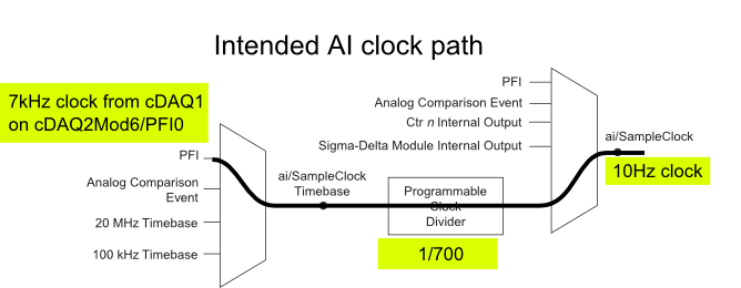
I have a cDAQ-9172 with an entrance module analog (9225) in the Groove 3 and a digital input module (9411 - 2 MHz DI) into the slot 6 (where the PFI lines are accessible). I want to use an external signal on et0/PFI0 to act as the clock for an analog input on the 9225 task. This signal comes from the cDAQ anothr chassis and is too fast for the task to HAVE it, so I intend to use the time base entrance and the divider to clock (as shown on page 31 of the cDAQ-9172 manual). See picture attached for a graphical representation of my problem.
If I have the wiring from the signal "/ cDAQ2Mod6/PFI0" in the DAQmx timing VI, get the error 200414 saying that "required sample clock source is not valid." It is strange because it is listed as "Direct route" in Max (the VI of polymorphic DAQmx Timing is configured as 'Sample clock') Q: why this route is not suitable for the task?
If I use DAQmx Timing property node and change the Source 'Sample clock Timebase' to ' / cDAQ2Mod6/PFI0 ", the task starts without error, but the separation seems to be forced to 256. If I try to change the properties of the separation of the time base, I get error-201100. Try to change the 'sample clock rate"doesn't have any impact on the task and the remains of divider"256 ". Q: why the 'Programmable clock divider"locked to 256 when using the PFI line or can you just not program directly?
I came across another error is the minimum speed on the PFI line. If I have the wiring (for the SamplClock Timebase) lower at 1 MHz, LabVIEW returns error-200077. The error message indicates that the minimum value is 1 MHz. 9172 manual shows the clock 100 kHz is an option for the time base, certainly less than 1 MHz. Q: What are the limits of upper and lower frequency for a clock signal on the line PFI for the ' Timebase AI/SampleClock "?
I looked on the site and in the DAQmx documentation for further explanation, but I have been unable to explain these strange behaviors. What are the barriers to entry of Timebase PFI and the time base "Programmable clock divider" preventing me to reach my goal here? If I can't do it directly, can I use the PFIn signal to feed an internal counter (to act as the clock divider) which could then generate the clock WAS at the rate I want? This method would allow me to perform a division arbitrary clock (unlike the ' 256', which seems to be forced on the PFI as a Timebase SampleClock.)
Finally, something seems odd that I can make an acquisition to 10Sa/s max but when I start a task using an internal timers of the cDAQ9172 and ask a 10Sa/s rate, the task really gives me a rate of 1612.9 sample/s while using the 12.8 MHz clock and a divider 7936 timebase. Q: Why can't the task to 10Sa/s?
I use DAQmx 9.7.0 and LV2012 SP1 (and I tried with 9.7.5 but I got the same results)
Thank you
Olivier
I got additional help Friday in another engineer at NEITHER and the solution to my original problem is actually very simple to get the clock from an external source path:
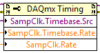
The idea of picking a PFI line for the basis of 'time' and the 'Programmable clock divider"(in fact, DAQmx calculate this number based on"HAVE sample time clock"and"Sample clock HAVE") works by using the node property below:
(SampleClock.Source cannot be resolved until the task is clerks/reserved, but the default option seems to be the time base that works well in this case.)
The question that I described earlier with the 9225 comes the module properties and the fact that it is a "Module of Sigma - Delta". That the module usually generates its own time of 12.8 MHz base clock (page 14 of the document 9225 # 374707) and the clock divisor is much less possible values than the other modules (must be a multiple of 256). It may use a different time basis from a PFI line, but it must be between 1 MHz and 13.15 MHz.
So a main clock between two chassis and tasks running at different rates of sharing should be easy and simple with most of the modules. With AI modules with Sigma-Delta converters add additional limitations and the master clock for the time base frequency must be selected to accommodate these module as well.
Another good news is that the Simulator seems to bear all these details and DAQmx (9.7.0 in my case) generates the same errors when you use a simulated chassis if you use real body. Play well!
-
integration of sampling time 6351 vs rate
I would like to know how the X-series Renault 6351 sample and other. More precisely, given a sampling rate of v and a p sampling period, the integration of each sample time must be less than p. My question is, during the sampling period, what actually happens? It integrates into all of the p? Y at - there a break-in? Is the integration time same p? Are there settings to affect how data acquisition uses the sampling period?
Basically, what I'm looking for is a complete description of what happens during the p, something like "p/3 running, integration time of 2 p/3.
So, there are two relevant 'rate' at the time of sampling on a MULTIPLEXED Board like the 6351 OR. There is the "sampling rate" which is the rate to which we take a sample for each channel, and then there's the 'conversion rate' which is the rate to which each channel is connected to the multiplexer in order to take a sample. I tried to show below
:
Whenever a sample is to be taken, each channel must be connected to the ADC in turn. Clock convert determines how fast it happens.
The conversion rate depends on the sampling frequency. If you choose a sampling frequency that is slow, we wait 10uS between convert each channel to allow more break-in. If the rate is too fast for waiting 10uS between each layer, we convert as fast as necessary to reach you sampling rates. At the maximum rate, the jury through each channel as quickly as possible in order to continue.
During the period of conversion, we do a number of things. Pass us the multiplexer to the channel, wait for a short time to resolve (this time it's what varies according to the sampling frequency), then we perform the conversion with the ADC (this is what you call 'integration time'). Time and Astro conversion are not user controlled; only the running varies according to your sampling rate and convert clock frequency settings.
It is not a forumla that I can give you for each of these pieces of how long takes. The best you can do is read the property of DAQmx Timing "I convert rate. This will tell you the total rate of switching, settling and conversion.
What do you need to know the time of integration for?
Maybe you are looking for
-
I get an error message when I try to listen to WMAL
I own an old Apple TV and I listen to the radio on my Apple TV device. This is the 2nd time that a station I listen to gave me an error message occurred and I can never listen to this particular radio station. What can I do?
-
Pavilion dv7 6c95dx: password reset BIOS
I forgot my password for bios
-
code 8007054f re KB9710323 my computer starts repeatedly try to install this update
Please notify that this update is causing problems on my computer as it starts four times, whenever it is stopped
-
EOS 1Ds Mk II rear wheel doesn't seem to work
Hello. My EOS 1Ds Mk II has a problem. The rear dial doesn't seem to work, that he will never change any setting in shooting mode. In all other respects, it works very well, but in M mode, for example, changes in command-line before shutter speed, bu
-
My Dell XPS 15 audio Jack does not work.
Hello, my new Dell XPS 15 audio Jack does not work. I just got this thing out of the box. I have updated the drivers and stuff, which doesn't seem to be the issue. I tried several headphones as well, the helmet is not the issue. I've isolated to this