Family of output voltage on NI PXI6225
I'm running a PXI basket with a NI PXI6225 IO card. I am trying to use the digital output ports, but they seem logical by default to TTL (+ 5V). He appears in the manual I should be able to change this with 3.3V logic but I cannot work on how do it. Using Labview 2011 sp1 so bad.
Thanks for any help offered!
This card only outputs TTL level. I think that it can read LVTTL however. If you really need LVTTL, use a voltage switching buffer. Search digikey for an octal buffer that can change voltage levels.
Tags: NI Hardware
Similar Questions
-
PCI 6221 generating an output voltage
Hi all
I'm trying to use a card PCI-6221 to provide a voltage of 5V analogue output and use it HAVE read the returned signal using labview. Anyone know how I can do this using this hardware device?
Thank you
Hi lrving9,
First you need the DAQmx driver, here is the link for you to install the latest version.
NOR-DAQmx 15.0.1
http://www.NI.com/download/NI-DAQmx-15.0.1/5353/en/If you already have it, so go ahead and take a look at this example:
It shows you how an analog DC output voltage.
Community: Output analog voltage constant
https://decibel.NI.com/content/docs/doc-18631So you have a block of connection to connect the signals?
If you do, then you can simply create a task to read a continuous voltage entry, as in this example
Community: - Input voltage
https://decibel.NI.com/content/docs/doc-25105If you do not have a connection block and have no way to connect the OD to HAVE, then you can read the inner channel of AO, as shown in this link (there is an example at the bottom):
It is Possible to read the value of the digital or analog output channels?
http://digital.NI.com/public.nsf/allkb/CB86B3B174763C3E86256FFD007A2511Also when you install the driver a few examples are installed as well, this shows you how to get them:
Where are the examples of NOR-DAQmx installed?
http://digital.NI.com/public.nsf/allkb/E3BAF6FC4017960B8625755A00525D37Kind regards
Caroline
-
How to get Strain Gage output voltage
Hello. I'm trying to do and calibrate a load cell with the installation of full-bridge strain gage. I use a NI9219 module with a cDAQ chassis. Is it possible to capture the actual output voltage? Signal Express gives me a value of strain, but I really need to know the output voltage. Where to look. Thank you! P.S. I only use this equipment on occasion and am not the more familiar with it, so keep things simple for me. Thanks again.
Then, it is quite simple. Two channels:
Ch01 - DAQmx acquire > an analog Signal > choose voltage: range min/max of the actuator load cell enter the installation of voltage input range (+/-5 k for example), and then create and apply a custom scale (choose the beaches of the table) where the +/-10V = full scale commercial load cell. Once applied "Scaling of units" should be updated automatically to display custom units you defined in the scale.
Ch02 Custom with Excitation voltage: range of input Signal (can probably leave default), scaling of units = voltage, E.g. Source = internal, Ex value = 2.5V, use Ex for unchecked staggered, depending on Configuration Configuration Terminal, Custom Scaling = none.
Optional: I normally add an amplitude and levels (analysis > measures Time-Domain) step, drag and drop the "DC" signal on both channels in the graph and create a scalar XY Chart, so I can see my field in real time.
Add a record to the ASCII step and save the two signals to Excel so you can draw your curve.
-
How to control the output voltage?
Good time after some time can get the output voltage, but this value is alwayscontinuous. How to control the voltage output through a Boolean? In
in order to get this tension when I want to.
Greetings.
Hugo SantosHi Hugo,.
If you use a LabVIEW project, you must set the time of sampling in the properties of the node (see SamplingInterval.png). But this time to refresh the data should be high enough. If you take into account this update of time trying to control your way out.
Kind regards
-
6009OEM output voltage and current
Hi all
Just try to make sense:
http://www.NI.com/PDF/products/us/20043762301101dlr.PDF
Page 3 says: high output voltage (push - pull, I = - 8.5 my) = minimum voltage 2.0 v maximum voltage = 3.5V but where can I find out what current can it provide and continue to produce an output voltage more than 4.2V? (4, 2V is the worst case for the high threshold of logic of a chip, I want to control).
Thank you!
J
Hello J,
As you mentioned is the maximum voltage of 3.5V when you have a high output voltage (push - pull, I = - 8.5 my). If you need more than 3.5V then you might need to change to an open-drain output. As you can see from the link you provided that you would receive a maximum voltage of 5V.
If you do not use an open-drain output you have to combine with a pull up resistor.
I hope this helps.
-
output voltage DAQ for external device control
Hi all
I have been using LabView 8.5 to acquire data from an acquisition of data USB Multifunction (1608FS of MCC DAQ) module. However, I now want to use this device even for controlling an optical shutter, but also to detect the position of the shutter sensor. Is it possible using this device in LabView?
I had no problems on the side of the acquisition but I was not able to generate any output voltages can any body in this case help.
Concerning
Steven
According to my quick google search, this device is listed as
DAQ module with eight 16-bit analog inputs and eight e/s digital
So there are no outputs only digital outputs.
-
How to configure the outputs voltage NI 9477
Hello
I'm trying to control a motor using a cRIO 9074 with the NI 9477 module. I would like to configure the output voltage of the module and if I understand correctly, they vary between 5 to 60 v.
How can I have a 24 v output?
Thank you.
JaneDoe94 wrote:
So if I understand correctly, I can use an exit as a switch?
If I choose resistance pull-up so the current stay under 1A, would this work?
For example, I am using R = 20 kOhm and DC = 24V. I need to stay below 5mA current.
9477 module is basically a relay to connect to the Earth. But beware of your voltage and current limits. The maximum current that can flow is 0.625 A by line. So make sure that you stay below that.
-
DAQmx task start-up delay / quickly generate arbitrary output voltages
Hello
(Sorry, I m new to this forum and could not find a reasonable solution by using the search)
I develop a c# multithreaded application that generates a waveform in the 'background' using output buffering simultaneously, captures the images via a firewire camera and treat them. I have a second channel DA free that I would use when debugging a marker in real-time so that I can check on an oscilloscope which is the relative condition of simultaneous processes, i.e. output a voltage of 1 V while treatment step 1, 2 Volts to processing step 2 etc. or I would be out a short spike at some critical point. This is done using a task as
DA_Task_sgl = new Task();
DA_Task_sgl. AOChannels.CreateVoltageChannel ("/ Dev1/ao0", "DA0" - MXVOLTAGE, MXVOLTAGE, AOVoltageUnits.Volts);
DA_Task_sgl. Control (TaskAction.Verify);
DA_Task_sgl. Timing.SampleTimingType = SampleTimingType.OnDemand;
DA_Writer_sgl = new AnalogSingleChannelWriter (DA_Task_sgl. Stream);then, when I want to change the tension
DA_Writer_sgl. WriteSingleSample (true blood);
A similar technique worked pretty well using Traditional NI DAQ, but with NIDAQmx and the concept of task, it seems that a voltage of output value takes about 1.5 ms (also of time CPU) which is too slow in many cases. With Traditional NI DAQ two consecutive calls to AO_VWrite() may generate a COB with only a few µs endeavors instead. I guess that the delay in the NIDAQmx is mainly determined by start and stop work, etc.
Is there a way to avoid all this (in NIDAQmx) and more direct access to the underlying hardware?
(Please Don t tell me that it is a limitation of Windows, NOR-Trad code clearly shows that it was possible, clearly the thread may be interrupted during the output voltage, but is also my treatment, exactly what I want TO check with this technique, but that 1.5 ms the delay is still there!)
(Currently used card PCI-6014 with NIDAQmx 9.x, but I think that it s not the card which is itself too slow, I can get the update rate Analog > 100 kHz on the string of voltage waveform via DMA)
Thank you
Joachim
Hi fabwes,
The snippet you posted on request AO. This means that whenever you write we go and search equipment to generate tension. Your assumption is correct, the slowness that you see is because of the job template. Whenever you are calling WriteSingleSample the task is launched, the tension is out, and the task is stopped. I suggest the following code:
DA_Task_sgl = new Task();
DA_Task_sgl. AOChannels.CreateVoltageChannel ("/ Dev1")("/ ao0", "DA0" - MXVOLTAGE, MXVOLTAGE, AOVoltageUnits.Volts);
DA_Task_sgl. Timing.SampleTimingType = SampleTimingType.OnDemand;DA_Writer_sgl = new AnalogSingleChannelWriter (DA_Task_sgl. Stream);
DA_Task_sgl. Control (TaskAction.Start);
DA_Writer_sgl. WriteSingleSample (false / * since we are already started, this parameter is essentially ignored * /, tension);
This slight change gets the load to start the task of the road before start you writing.
-
vary the value of output of the digital HIGH output voltage.
Hello
Is it possible to vary the values of the NOR-DAQ HIGH output voltage. If Yes please tell me how to do the same. I want to reduce tension before moving out of my camera, digital signal as my rating of device is only 3 volts for the digital HIGH.
Kind regards
Pradeep.
The digital output voltages cannot be changed on your USB-6259 (that you mentioned that you use in a different thread). Please see the specifications for more information on the digital logic levels used on your Board.
Best regards
-
Find the strength of output voltage
My VI generates a graph displays the output voltage of two 250 lbf (http://search.digikey.com/us/en/products/FC2311-0000-0250-L/MSP6952-ND/809398) to load data sheet (http://www.meas-spec.com/downloads/FC23.pdf) cells. I am trying to determine how much force is applied to the my output voltage load cell. So basically how to convert the output of a tension force (Newtons). Thank you.
Sheet indicates that the nominal power is 100 mV at load full scale and 0 at no charge. If you neglect the mini-maxi offset of zero and span min - max variation, you have 250 lbf/100 mV. Then multiply by the conversion factor appropriate in newtons. To account for the offset and gain variations, you might use a linear correction by solving the equation of a line (y = m * x + b) at two points, one with and without load near full scale.
Some DAQ drivers put the scale included.
Lynn
-
6008 OR using Labview 8.6 variable output voltage
Hey guys,.
So my goal is to create an output voltage of my USB 6008 OR which can be set from 1 - 5V in Labview. (This output goes to a mass flow controller that varies its pressure based on an entry 1 - 5V) I'm using Labview 8.6 and far I used the DAQ to create analog output of fishing, but I can't figure out how to get a right voltage DC output. Is this possible? Also to measure the output so I connect the cable on the + and - or the + and gnd? Please help me!
The tension of desire is just a digital control.
You should probably just stop and take one of the free tutorials. A digital control is a very basic concept.
-
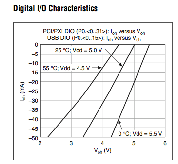
What is the level of output voltage of the NI 622 X
There is no clear definition of the level of output voltage of cards X NI DAQ 622 in the spec.
Are they drain open output? What is their level of voltage? The programmable ETC, voltage level is able to be configured to 3.3 or 5V?
Look at the graphs on page 8. This is not the usual way of Voh specification, but is is very informative. Other charts display different values from the DMV.
Lynn
-
It is current on the analog module USB NI 9263 output voltage limit (+/-10 v)?
It is current on the analog module USB NI 9263 output voltage limit (+/-10 v)? I try to run a current controlled resistance, but cannot get the required current. The servovalved has a parallel internal resistance of 80 ohms and requires 20 my full operation. Ohm's law: (.02 A) * ((80*80) /(80+80) ohms = 4.5 v) Yet, the required voltage, do not move the servo. Outside the material error (continue this by other means), what could be the problem?
Have you checked the Manual?
Page 12 1 says my.
For servo, you really need some kind of amplifier. See if the manufacturer provides the electronic driver for it.
-
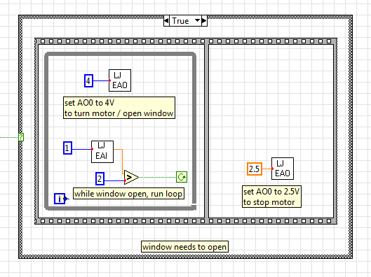
Gradual increase of the output voltage
I use EAnalogOut.vi from LabJack U12 for the U12 4 volts AO0 value. The instant change of output voltage is at the origin of the problems with the engine I use, so I ask: does anyone have an idea how I could program in the current diagram. To move gradually to 4 volts when first executed in the while loop and then little by little to down to 2.5 volts.
Instead of having a value of 4 GB in the analogue output VI, you must have your loop to change the value in small steps. Have a wait function in this loop. Use a shift register to feed into it and increment this registry to offset by small steps. Between the timer of the waiting and the number of steps and the size of the markets, you set will determine how long it takes to ramp to 4 volts. And of course more stages with smaller increments will be a smooth ramp.
-
How the output voltage is coded on 16 bits DAQmx devices?
In our laboratory, we have two devices DAQmx, the NOR-PCIe-6363 and the NOR-PCI-6733. Both have 16-bit for bipolar analog output precision. I understand that the small voltage difference that can be made is 2 * Vref/2 ^ 16, where Vref is the reference AO voltage (10 Volts or externally provided for 6733, 10 or 5 Volts or externally supplied for the 6363).
I wanted to know how the output voltage is coded. DAQmx functions take 64 bit floats as input, and at some point, they must have their reduced accuracy. How is this done rounding, is a floating point around the nearest possible tension, or is always rounded down or always rounded upward?
What is all the possible output voltages? Some diagrams in NOR-DAQmx help/measurement Fundamentals, signals, Analog, sampling considerations seem like they could involve the maximum voltage + Vref is not achievable, so I think that is all of the possible tensions - Vref + 2 * Vref * n/2 ^ 16, with n ranging from 0 to 2 ^ 16-1 included. This includes - Vref and does not zero but + Vref.
Could I get confirmation on this point, or be corrected if it is wrong?
Hi Chris,
The scale of writing DAQmx version performs double floating precision scaling and then he made a turn, the closest to convert the resulting code of the DAC to double int16_t (or uint16_t for unipolar devices). Floating point scale includes the custom scale AO if you have configured one, the conversion of volts or AMPS to the codes of the DAC and for some devices, the calibration scale.
You can check the coefficients of scaling using the AO. Property of DevScalingCoeff. It takes V / A-> CAD codes and scaling into account calibration, but not the scales to customized AO.
The PCIe-6363 X series devices preset scaling in software. The internal reference of the AO is slightly higher than 10V, to correct the errors of gain and offset does not limit the output range. It also means that you are not limited to 9.9997 V on this device when you are using an internal reference.
The PCI-6733 uses calibration DAC instead of software scaling. RAW - 32768 means - 10 V, 0 corresponds to 0 V, 32768 is impossible because of two of the 16 bits of the add-in and 32767 translates 9.9997 V. When you continue 10 V to write DAQmx with this device, DAQmx he forced into 9.9997 V.
Note that for these two devices, the absolute accuracy full scale includes over 305 uV of error. Look at the tables of absolute precision AO in the specs of the device for the full story.
Brad
Maybe you are looking for
-
Cannot modify 'share page' preferenc are
When you share a page, I made previously by e-mail the default choice. I have more like this setting and you want all the options available when a page sharing. I erased all the data/settings & uninstalled/reinstalled that disabled by default.
-
Equium A100-303: looking to add more RAM
Hello I recently bought a laptop equium A100-303 and am lookin to add more RAM. I was just wondering if it should be buffered or non-buffered or is it important? I currently have 1 GB of ram (512 + 512 MB as it is a dual core processor) and I'm looki
-
X 220 i7 8 GB very slow WEI for processor
Hi guys I searched and read many things on the limitation and the difference between 65W and 90W power provides all have an effect on the above topic. However, none of the fixes seem to work. Many of you report a 7.1 WEI while I can't get 3.4 with th
-
Hello. Since the 1.07 update, I no longer get a beep when the focus is locked. I get no audio at all. Is there a solution, as the reloading of the update? Can you help me please? Thank you, Dan.
-
When I on cmd.exe and type slmgr.vbs it says that the file is missingand when I enter the product key for windows 7 ultimate it's license-computer bios is missing. When I try to install windows 8 using product key to say we cannot connect us check yo