filter of signal distortion
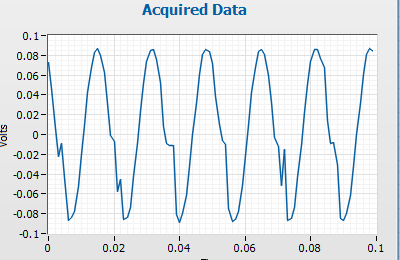
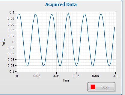
Hello everyone. I'm trying to filter a signal using filter Butterworth that VI included with LabView. The problem I have is that it is a signal in time real get sampled at a certain speed with a certain block of samples. The filter seems to do its job properly for all samples in the middle of the block, but it doesn't for the first part.
I have attached two picture to show the difference with and without the filter. It is a sine wave.
I think that the problem comes from the Convolution of the input signal filter and distort the signal in this way. I was hoping people can say this is the problem and help me to find a way to a solution.
I can show you my code as well, but to me, that this is a general problem with filtering, rather than my code. If you think I'm wrong please tell me.
David.
Tags: NI Software
Similar Questions
-
I try to measure the AC current measuring brownout on a resistance. Using a NI 9215 signal looks like this and is not accurate.
When I plug the same signal to a USB not cheap-o 6008 signal seems fine and I am able the same voltage of RMS of my multimeter.
I would prefer the sampling frequency higher the 9215 since we are looking for distortions of the AC signal. What I'm missing here? Thanks in advance.
Hello
Both modules are connected in differential mode?
With NI 9215 - always shall be connected to COM (with resistance 1MOhm DIFF or directly to the CSR) because it is an isolated module (see fact sheet).
USB-6008 has no isoloation, but still need to bias resitors connected between IA a COM.
Maybe it's the cause of what you see.
Best regards
Matej Zorko
-
DAQmx split or filter the signal
Goodday,
A map of 4461 PC, there are 2 mic's connected. I use the Read.Vi of the DAQmx for it with 'ai0:1' as physical addresses.
These signals is used to calculate the rms value.
And this value is sent to
Ai0-Ao0 online
and
AI1-online Ao1
But sometimes I want to use only one microphone and so only for example use "ai1" However when I do this the Ai1 signal is at Ao0.
AI1-Ao0 online.
It seems that the Read.vi write all channels "signals channel 0" instead of "Ai1 to waveform channel 1".
How can it be changed or filtered?
And is there a way to create a drop down menu to select Ai0:1 (multi-channel) control? one is to create is now only for selection of a channel.
The command select channel a constant has a menu drop-down to select one or more channels. Just use the browse option.
If you have only one selected channel, you don't have that one in the waveform table, so if you still want to affix a specific chart, ai1 put function index in array inside a case statement. You have three different only case - ai0 ai1 only, ai0 and ai1. Wire instruction box for graphics.
-
Low-pass filter before the NI 5112
Hello
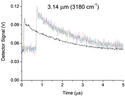
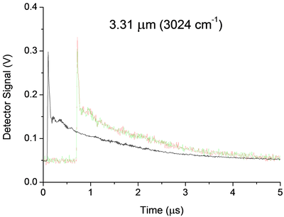
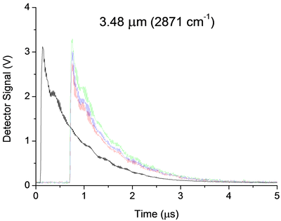
I currently use a 5112 AND measure the signal of an infrared detector in an experience of ring to the bottom of the cavity. Below are three examples of signals. My main question is how I can implement a low pass filter, passive preference, before my 5112 OR undistorted extremely my signal due to the impedance mismatch. Now a few details:
Some unique captures for each wavelength are shown in color, while average 25 pulses appears offset in black. The range and offset are chosen in each case in order to minimize the noise of "scanning". In the case of 3.14um, the noise that you see is about 25 times noise from scanning. They were taken without the limitation of BW and 100 ms/s mode.
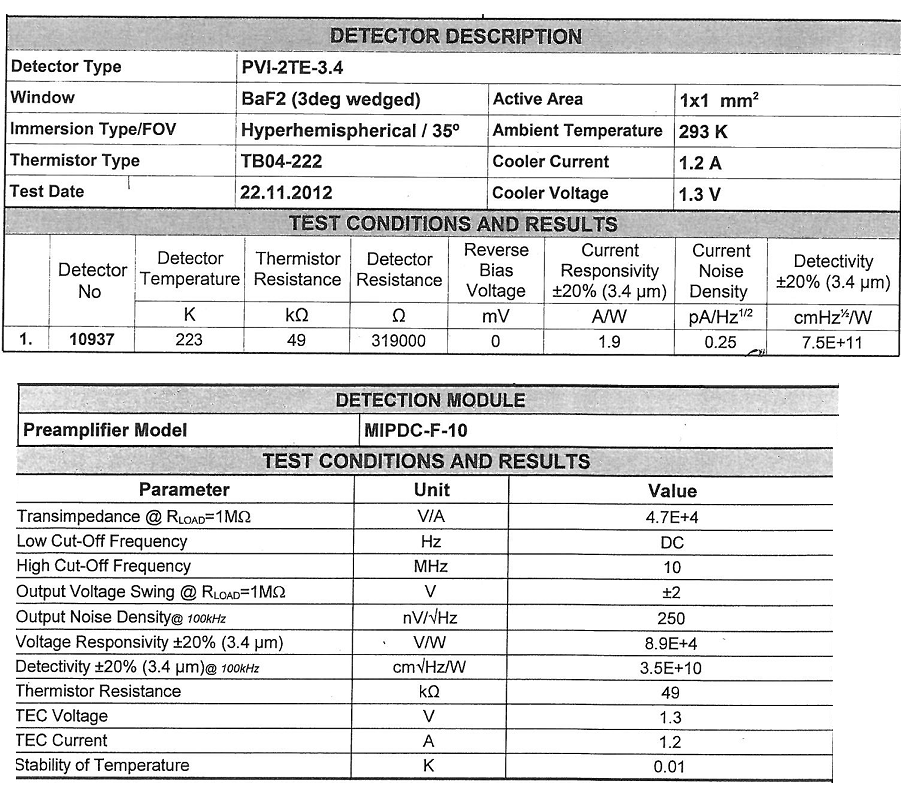
The detector (Vigo MIPDC-F-10) has a bandwidth of 10 MHz. I think it is a low impedance and is intended to be harnessed with 50Ohms, however its documentation confuses me, and I'm waiting for a definitive answer from the provider. 2.4 part of the manual says 50Ohms recommended, however the Datasheet and our map calibration (below) seem to suggest 1 MOhm is recommended!
There are a few strange oscillations with a period of almost 180ns in our signal that I thought were due to the impedance mismatch existed in the system before I changed it:
-Detector
-1 metre 50 Ohm SMC Cable BNC (RG-174)
-Inline BNC connector
-meter 5, 75 Ohm BNC to BNC cable
-Digitizer, DC, no BW limit, 100 ms/s, 1MOhm | 30pF
When I saw this configuration, I knew something wasn't right and I even he modeled in LTSpice and he showed the same period of oscillations. But now, the Setup is:
-Detector
-1 metre 50 Ohm SMC Cable BNC (RG-174)
-BW digitizer, DC, limit, 100 ms/s, 50 Ohm
And we still have oscillations, even if the period seems to have changed to 320ns all about. These oscillations, which remain are 99%, probably due to our drop-down ring cavity experiment, however if anyone has recommendations on possible causes or ways I can confirm it is not because of my chain of detection they would be more than welcome!
Now, the main question. Between the 50 Ohm 1 meter cable and the scanner I would insert a low pass filter. The BW limit has helped reduce the noise, but it can certainly still be further reduced without any lose to our signal. That's because we cut the beginning of the signal and then measure just the the decay time, which is relatively long and smooth (1 to 2 times 1/e US). Thus, in the future I may even want to try to eliminate the oscillations 320ns, but I'm afraid that this much filtering will distort the signal too. Therefore, for the immediate future I'm just looking to 'replace' the filter BW 20 MHz, with something like 1 or 5 MHz.
Of course, I would disable the BW limit on the digitizer to avoid additional confusion, but nevertheless, I'm not sure how to approach the problem. Usually I do a lot of research and try different solutions. However, I don't have access to all components to this work, so everything should be ordered, and I don't have a lot of time to experiment. Ferrites seem like a possible solution, however not sure how effective they are at this low frequency or the way they work with coaxial cables. I know that the filter passes low RC base, but the 50Ohms (or 1MOhm | 30 pF if I change it) seem to make it impossible. I guess an op-amp based one might work, however the large input impedance is the impedance of coaxial cable... etc...
All of the recommendations of the technique or red resources wort would be welcome. Thanks for your time.
A possible way to separate your artifacts electric and the cavity is relatively simple. You take the data at three wavelengths. For each of them, make a simple exponential decay (for example exponential Fit.vi) adjustment to your data, then subtract this signal. You should have something that oscillates on an average. Compare the residual signals for all three wavelengths, either visually or with something like a power spectrum. Anything in the three is probably the electronic (and you could possibly model and subtract it rather than trying to eliminate it). This could break if the rise time of the signals are different, because that will include elements of different frequency.
I am not convinced that you need to filter your signal before taking data. As you said, any filter will distort your final signal. My preference would be to take the raw signal and apply a filtering in the analysis. LabVIEW has a rich filter, so you can experiment later. If you apply a filter before the digitization of data, you take you will never receive data. However, if you know that your data has no component of your proposed cut filter frequency, you should be good. An analysis of the power on your current spectrum should tell you this. Be careful. Your form of rise time may have information you want later. If you filter, you will probably slow it down.
Good luck! Let us know if you need more information.
-
Hi all! Stage of a part, I need to develop a system of data analysis of a three-dimensional accelerometer. With overall good progress in my project I encounter however a problem of filtering:
I want to realize an AutoFilter (who lisserai my signal to optimally curves) in Labview 8.6.
After long hours of research, I came across various information about wiener filter only I did not understand everything not absolutely sure it's solution to my problem besides being...
Is there a kind soul to remove me this bone of the foot?
If you think of an idea, a method, see United Nations VI, please answer me.
Thanking you in advance,
Hi all
Finally, I think anyway, found the answer to my problem with the 'Harmonic distortion Analyzer' VI gives me the Nyquist frequency, which is ultimately what I tried.
Thanks to her determination I can impose it as cutoff frequency pour my "Adaptive Filter' (a simple first order low pass pour info) and therefore automatically filter every signals.
Again thanks Krsone pour your answer, it is true that pour an optimal smoothing of the solution you had proposed to me seems very effective

-
Hello
Is there a way to (bandpass) filter complex signals in Labview? I Googled it but I don't seem to find a way to filter complex signals (a + i * b).
Edit: The block of normal bandpass filter will not work because it does not accept the complex entries
Divide into re / im, filter individually, recombine.
-
Filter low pass analog (anti-aliasing filter) external to the NI USB 6251 housing
Hello everyone!
-I m trying to acquire an analog signal of tension (high frequency content) using a connected to an edge NI USB-6251 BNC-2110. I learned in this Labview Forum that NI USB-6251 has no analog low-pass filter programmable (or anti-aliasing filter), so that I can't help but jitter when scanning my signals. For my application, the cutoff frequency of the analog low-pass filter must be equal to 100 kHz or MORE (maximum of 500 kHz). A possible solution to solve my problem, would be to work with an external analog low-pass filter before you scan the voltage signal. Based on this I'd like to know:
(1) national Instruments develops analog external filters? I need a filter which also has one output, analog, so that I could send also the low-pass analog filter filtered signal to my NI USB-6251 box to scan correctly it!
(2) what model of external low pass filter would be compatible with the NI USB-6251 housing?
Any help would be much appreciated!
Best regards!
Hello
all high resolution of the M series (628 x) cards are equipped with a filter low pass which can be enabled or disabled programmatically. For the anti-aliasing filter feature, examine the boards of National Instruments DSA (dynamic signals Acquisition) acoustic and vibration measurement
currently the NOR 9221, 9225, 9227, 9229, 9233, 9234, 9235, 9236, 9239 and 9237 C Series modules feature anti-aliasing filters. These modules are intended for the high accuracy measures for which anti-aliasing filters are a necessity.Houssam Kassri
OR Germany
-
Moving average filter w / continuous data acquisition
I'm looking to filter multiple signals of noisey. I am currently using a NI9203 w / a cDAQ-9174 sampling to 1000 Hz. I use DAQmx vi to start the task and acquire the signal. I tried using coefficients.vi smoothing filter combined with IIF filter.vi (Avg.png movement) it seems to work for simulated signals and recorded data. However, when I try to use this configuration for an average of real time it cut everything just all signals to zero. I looked into the use of shift registers, but to get the necessary result, it seems that I have to use hundreds of items.
In the end, I'm trying to filter the signal to get a constant more of reading for the user. For example during operation, the user needs to review the current state of the values in real time. It's currently difficult when the noise indicates the values of +/-100 changing every 100ms.
For any help or suggestion would be appreciated, thanks in advance.
Thank you all for the help and advice. I have attached the vi that I used to solve the problem, one of my major problems was not timing DAQmx using. Attaché in 2012 and 2013.
-
Need help to write a program for the acquisition of signals.
Hello
I need to write a program that will do the following:
1 acquire two signals simulated,
2. make 10 averages the signal,
3. filter the signal,
4. display the signal in its raw form and the power spectrum (fft),
5. save the data using writing to the file vi
I tried it for awhile, but there's always something does not... None of the experts LabVIEW here can help me?
Thank you 1 million.
-Deet
No one here is going to do your homework for you. Please join what you have written so far and explain the specific problem that you are experiencing.
-
Hello
I have a problem with the NI 9215 module, I use Ni9215 with NOR-ISB-9162, systems of six measures and the release of nor are in the enclosure. I have the signal distortion when I tried to measure the signal of a phase of the system 3 phases and do not have this strain when trying to measure simultaneously two or three phases. Another problem is when I tried to measure simultaneously both signals from different voltage dividers - I have terrible strain (scheme_6).
Might well want to explain to me, why I have this distortion of the signal on OR output.
I hope for your help.
Thanks for all answers, there is no problem in NI9215, the problem was high-potential on the 'ground '. That caused measures identified. So be careful with potential in your field and the common PIN of the NI9215.
-
Determine the position of a part of the signal on a graph
Hi all
I have a problem. I determine the position of a part of the signal on a chart. So, I have to determine the maximum value of the part (this is not a problem).
Signal a lot of noise. I did some filtration but still signal have noise. Concerning this, filter change signal, two later when I take one measure, there is a possibility that this is not true.
Anyone has idea how to determine the position of a part of a signal automatically, for the various signals (similar).
There are photos attached where is what belongs to an interest in a signal. There is a VI where is an a test signal.
Thank you
Hello
From the screenshot, I understand that you only interested in the local maximum of the signal.
There is a VI that detects peaks when you specify a certaing point and this point maximum width.
Later, it's just a matter of setting the value of local maximum of you. Basically, you'll have to point once again got 1 d table than VI.
I enclose a VI that can be a good starting point for your application.
Best regards
Ion R.
-
Help: Cannot filter a graph of function text
Hi all
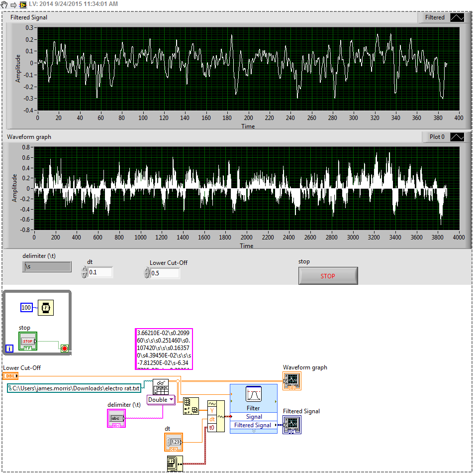
I have a text file that I use to generate a graph and it works well. However, when I try to connect this table on a waveform to build it shows a wire broke (as shown in the image below).
I added the waveform build because it won't let me filter the signal directly from the table. I found this solution here http://goo.gl/wjacvO
How can I filter my signal using this function? Thanks in advance.
FYI, you must assign the default values where you work when you share a code. Your delimiter is '\s' and I have no idea what is your value of dt.
You should play with your cut filter to match your data rate. It has been set to 100.
I did work with 0.1 0.5 switching and dt:
-
I filter a signal of amplitude of the 0.2 Volt connection. It consists of pickup and noise of the line. How to do? Is the software filters are enough or I have to design a filter material?
Hi sukhiray,
If you have less than the full version of LabVIEW, there are several software filtering options available in the category of Signal Processing. You can configure your thresholds and the order of the filters and choose between the different types of filter. The choice between hardware and software depends on your needs and signal.
-
Hello, I have another problem here, just started to learn the filtering and decided to practice on the job making, im if you have this one question: I have two signals on channels of entry of two pressure sensors that come with high noise. I tried to split the signals, filter, and then merge again to send to waveform, but it does not somehow, and I thought that if there was a specific filter for multiple channels, I read that some TREES can divide signals itself and merge them automatically, but I couldn't find one. suggestions for beginners? Thanks in advance

PS by the way, managed to filter one of the signals manually split and for some reason, the waveform to the display of the data of pressure with sound sensor stops working after apprx 3 sec, it kind of drags a bit and then goes black blank, so any suggestions on this point, would much appreciate
PPS two graphics of waveform showing the initial data of the sensors go blank after a while at the same time black

Hello Pomplamoose,
I forgot to mention something: If you set playback VI to N samples then wire a constant for the number of samples per input channel. A good way would be to read in samples of 1000 per iteration.
Part Fliltering:
First of all, if you want to filter the high sounds you use Lowpass Fliter.
Attached you will find your VI with 2 ways how you can filter your signals.
(1) easy solution with express filter VI.
(2) VI of Butterworth filter, the way in which you the tried.
Some explanations to 2):
If you use the butterworth VI as a low pass/high pass filter filter, it ignores the entrance of high cut-off frequency. The entry, you should use is the lowcutoff FREQ.
In VI I provide you with there is no synchronization of the signal information once it is filtered, because you only use data of Y of the type of waveform. If you have calendar information in your signal you could do that with the construction of a waveform type after you filtered the data Y.
Therefore, you have no synchronization of the signal you need to resize the chart you can see the filtered together signal.
To merge the signals after you their filtered, you have 2 ways:
(1) build an array of filters.
(2) use the signals of fusion VI.
If you need help just ask, otherwise mark as resolved.
Kind regards
Markus Mayr
-
Is there a tool in Photoshop elements 13 which helps eliminate distortions 'Keystone '?
Or use the filter "filter/correct lens distortions.

Maybe you are looking for
-
Why Apple have downgraded app music in iOS10?
I have never written a comment or opened a discussion here but I felt compelled after the last updated iOS10... I do not understand why Apple have passed their music app when they are competing with major players such as Spotify etc. As a music lover
-
HP eprint unavailable after Chromebook updated this morning?
Is this a general problem with the HP Server. Also message to the eprint Google that HP does not communicate? Message reads could not get information about the HP printer. DeskJet 3050 has Samsung Chromebook
-
How do I get 'My recent documents' on my Start menu? (Windows XP)
It took me a long, long time to ask this question - did not want to appear stupid I guess. My PC coming up to two years and never had 'My recent Documents' in my Start menu, don't figure out how to do something that should be very simple. Help, pleas
-
I checked everywhere before the release of Windows 7, even the Microsoft store and anyone with a copy of XP not found for sale. Although Microsoft still wants to push Windows 7, I found many other providers with XP for sale. Since Microsoft seems to
-
I just got my key signing files and installed all 3 this morning, but I had a problem with my JDE. I reinstalled the JDE, but now can't use the signature request function. I tried to reinstall the CSI, which is apparently a mistake. Don't know what