Find the strength of output voltage
My VI generates a graph displays the output voltage of two 250 lbf (http://search.digikey.com/us/en/products/FC2311-0000-0250-L/MSP6952-ND/809398) to load data sheet (http://www.meas-spec.com/downloads/FC23.pdf) cells. I am trying to determine how much force is applied to the my output voltage load cell. So basically how to convert the output of a tension force (Newtons). Thank you.
Sheet indicates that the nominal power is 100 mV at load full scale and 0 at no charge. If you neglect the mini-maxi offset of zero and span min - max variation, you have 250 lbf/100 mV. Then multiply by the conversion factor appropriate in newtons. To account for the offset and gain variations, you might use a linear correction by solving the equation of a line (y = m * x + b) at two points, one with and without load near full scale.
Some DAQ drivers put the scale included.
Lynn
Tags: NI Software
Similar Questions
-
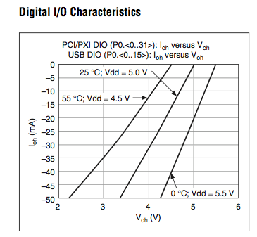
What is the level of output voltage of the NI 622 X
There is no clear definition of the level of output voltage of cards X NI DAQ 622 in the spec.
Are they drain open output? What is their level of voltage? The programmable ETC, voltage level is able to be configured to 3.3 or 5V?
Look at the graphs on page 8. This is not the usual way of Voh specification, but is is very informative. Other charts display different values from the DMV.
Lynn
-
vary the value of output of the digital HIGH output voltage.
Hello
Is it possible to vary the values of the NOR-DAQ HIGH output voltage. If Yes please tell me how to do the same. I want to reduce tension before moving out of my camera, digital signal as my rating of device is only 3 volts for the digital HIGH.
Kind regards
Pradeep.
The digital output voltages cannot be changed on your USB-6259 (that you mentioned that you use in a different thread). Please see the specifications for more information on the digital logic levels used on your Board.
Best regards
-
I want to find the digital audio output on my Pavilion vd6853ea notebook
I spent far too long trying to find where this output.
I have a very good stereo and at the moment am through a USB cable to connect to my DAC.
It seems that there is an output digital realtec somewhere on the laptop as it appears not when I go to the playback devices and it tests ok visually.
The 3.5 jack plug is just analog and hybrid not a spdif.
Where is he?
Please help as I am getting really fed up now!
Hello
macapaca666 wrote:
I thank very you much for the quick response.
I thought that might be the case.
Can I ask you a few more questions please?
If I want to get one don't output digital audio not using a HDMI (my DAC has not this entry), I can get a good result with something like a Musical Fidelity V USB converter S/Pdif link or a digital audio interface M2Tech Hiface? Sorry, I can't make a recommendation on one of these products as I am not familiar with them.
Is it possible to change the soundcard with optical or coaxial output? The sound of your laptop is an integrated solution. It's a (built-in) welded chip on the system board. It cannot be updated.
Thanks again for the kind help!
John
Best regards
ERICO -
How to add the phase parameter to array of waveform in the DaQmx continuous output example?
Hi all
I'm quite beginning to Labview. I just wanted to know how can I add stage information for the module of waveform existing as shown in the example of output Voltage-Continuous DaQmx.
SEEE attached, I thought that the "output" is actually a built-in control, is there anyway I can add the phase as an additional parameter which?
Thanks in advance for any help.
Eric
If you press ctrl + H, the context help window opens, and you can hover over the generating function VI to see its inputs/outputs, but also to navigate to the detailed help. As you can see from this screenshot, there is an exit for the phase which is separated from the output waveform.
-
How to control the output voltage?
Good time after some time can get the output voltage, but this value is alwayscontinuous. How to control the voltage output through a Boolean? In
in order to get this tension when I want to.
Greetings.
Hugo SantosHi Hugo,.
If you use a LabVIEW project, you must set the time of sampling in the properties of the node (see SamplingInterval.png). But this time to refresh the data should be high enough. If you take into account this update of time trying to control your way out.
Kind regards
-
How to configure the outputs voltage NI 9477
Hello
I'm trying to control a motor using a cRIO 9074 with the NI 9477 module. I would like to configure the output voltage of the module and if I understand correctly, they vary between 5 to 60 v.
How can I have a 24 v output?
Thank you.
JaneDoe94 wrote:
So if I understand correctly, I can use an exit as a switch?
If I choose resistance pull-up so the current stay under 1A, would this work?
For example, I am using R = 20 kOhm and DC = 24V. I need to stay below 5mA current.
9477 module is basically a relay to connect to the Earth. But beware of your voltage and current limits. The maximum current that can flow is 0.625 A by line. So make sure that you stay below that.
-
It is current on the analog module USB NI 9263 output voltage limit (+/-10 v)?
It is current on the analog module USB NI 9263 output voltage limit (+/-10 v)? I try to run a current controlled resistance, but cannot get the required current. The servovalved has a parallel internal resistance of 80 ohms and requires 20 my full operation. Ohm's law: (.02 A) * ((80*80) /(80+80) ohms = 4.5 v) Yet, the required voltage, do not move the servo. Outside the material error (continue this by other means), what could be the problem?
Have you checked the Manual?
Page 12 1 says my.
For servo, you really need some kind of amplifier. See if the manufacturer provides the electronic driver for it.
-
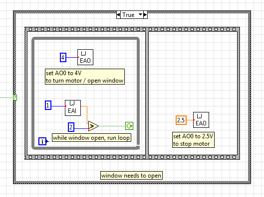
Gradual increase of the output voltage
I use EAnalogOut.vi from LabJack U12 for the U12 4 volts AO0 value. The instant change of output voltage is at the origin of the problems with the engine I use, so I ask: does anyone have an idea how I could program in the current diagram. To move gradually to 4 volts when first executed in the while loop and then little by little to down to 2.5 volts.
Instead of having a value of 4 GB in the analogue output VI, you must have your loop to change the value in small steps. Have a wait function in this loop. Use a shift register to feed into it and increment this registry to offset by small steps. Between the timer of the waiting and the number of steps and the size of the markets, you set will determine how long it takes to ramp to 4 volts. And of course more stages with smaller increments will be a smooth ramp.
-
How the output voltage is coded on 16 bits DAQmx devices?
In our laboratory, we have two devices DAQmx, the NOR-PCIe-6363 and the NOR-PCI-6733. Both have 16-bit for bipolar analog output precision. I understand that the small voltage difference that can be made is 2 * Vref/2 ^ 16, where Vref is the reference AO voltage (10 Volts or externally provided for 6733, 10 or 5 Volts or externally supplied for the 6363).
I wanted to know how the output voltage is coded. DAQmx functions take 64 bit floats as input, and at some point, they must have their reduced accuracy. How is this done rounding, is a floating point around the nearest possible tension, or is always rounded down or always rounded upward?
What is all the possible output voltages? Some diagrams in NOR-DAQmx help/measurement Fundamentals, signals, Analog, sampling considerations seem like they could involve the maximum voltage + Vref is not achievable, so I think that is all of the possible tensions - Vref + 2 * Vref * n/2 ^ 16, with n ranging from 0 to 2 ^ 16-1 included. This includes - Vref and does not zero but + Vref.
Could I get confirmation on this point, or be corrected if it is wrong?
Hi Chris,
The scale of writing DAQmx version performs double floating precision scaling and then he made a turn, the closest to convert the resulting code of the DAC to double int16_t (or uint16_t for unipolar devices). Floating point scale includes the custom scale AO if you have configured one, the conversion of volts or AMPS to the codes of the DAC and for some devices, the calibration scale.
You can check the coefficients of scaling using the AO. Property of DevScalingCoeff. It takes V / A-> CAD codes and scaling into account calibration, but not the scales to customized AO.
The PCIe-6363 X series devices preset scaling in software. The internal reference of the AO is slightly higher than 10V, to correct the errors of gain and offset does not limit the output range. It also means that you are not limited to 9.9997 V on this device when you are using an internal reference.
The PCI-6733 uses calibration DAC instead of software scaling. RAW - 32768 means - 10 V, 0 corresponds to 0 V, 32768 is impossible because of two of the 16 bits of the add-in and 32767 translates 9.9997 V. When you continue 10 V to write DAQmx with this device, DAQmx he forced into 9.9997 V.
Note that for these two devices, the absolute accuracy full scale includes over 305 uV of error. Look at the tables of absolute precision AO in the specs of the device for the full story.
Brad
-
Hello
I'm doing a tension of 3-story ramp. One who goes from 0V to-1V can-1V to + 1V and finally wear the voltage of + 1V to 0V. The main feature is that I try to sync input only a channel for the median ramp. I get the expected input but my output voltage on the oscilloscope is not correct. The entry and exit and goes a box NI USB-6229. On the oscilloscope, you can consider the following issues:
1. There is a gap between the end of the 1st ramp and the beginning of the 2nd ramp
2. once the main finished once, ramp voltage immediately returned to-1V and again another ramp until it reaches 0V, then levels out for another short period of time
3. the cycle then repeated from the beginning, completely missing ramp 3
If all those who think they might help in any way, I would appreciate any input. If someone tries the attached program: I used these settings: entry rate = 1000; #data points = 200; DT = 0.0005
-Kyle Shiel
If you want to copy your ramp of 3 floors without any pause between steps, you must accumulate the entire waveform (all 3 steps concatenated) and write in your output task at once (similar format This example, but no need to start and you need to replace with your own generated table waveform).
I would just at the entrance to the beginning of the analog analog output task. You can use the DAQmx Trigger Start.Delay property if you want to wait for the 2nd phase begin to acquire, or you could simply acquire all 3 steps and analyze what you need.
Best regards
-
Where can I find the codes output once run chkdsk when you restart?
Microsoft Search gives me tons of information on running chkdsk and the different options and the meanings of exit codes. I stumbled today on my D drive with the /f option requiring a reboot. I thought that Windows can display a screen or something after the reboot, showing the exit code, but no luck. None of the MS pages I've seen tells where to find the exit code. I have tried but no luck, the event viewer. Is there a log somewhere?
Exit codes are transitory in nature and generally are available for the following statement after the statement of chkdsk when included in a script file or .bat. Event ID has nothing to do with the exit code. CHKDSK has only four codes of output that are described here:
"Microsoft Windows XP - Chkdsk"
<>http://www.Microsoft.com/resources/documentation/Windows/XP/all/proddocs/en-us/chkdsk.mspx?mfr=true >It makes sense to use these codes if you write a script that checks the other readers that the drive of Windows OS, like windows in the car is always in use and cannot be verified before Windows (and ergo any script) is executed. The information that you retrieved from the journal applications you said much more than the c code output. If you need check the result of a Chkdsk operation powered by programming, you will need a tool such as "psloglist" to empty the log entry and scan from there.
HTH,
JW -
Can someone help me find the output in bridge CC option?
Can someone help me find the output in bridge CC option?
http://helpx.Adobe.com/bridge/KB/install-output-module-bridge-cc.html
-
How the NI9263 binary code is mapped with output voltage?
In the specification of NI9263, he says he is 16 bits and has a range of +-10V output. Does this mean that the 16-bit extends the range of - 10V to + 10V? I don't need one bipolar output, so that means that I am limited to the resolution of 15 bits, if I want to, for example, only output 0 - 10V?
Hi kingman.
I made a mistake, I checked the 9263 specifications and this device is set to +-10Volts. However, if you set the interval of output from 0 to 10 Volts, you still 305.2 uV as a detectable change.
Carmen C.
-
6009OEM output voltage and current
Hi all
Just try to make sense:
http://www.NI.com/PDF/products/us/20043762301101dlr.PDF
Page 3 says: high output voltage (push - pull, I = - 8.5 my) = minimum voltage 2.0 v maximum voltage = 3.5V but where can I find out what current can it provide and continue to produce an output voltage more than 4.2V? (4, 2V is the worst case for the high threshold of logic of a chip, I want to control).
Thank you!
J
Hello J,
As you mentioned is the maximum voltage of 3.5V when you have a high output voltage (push - pull, I = - 8.5 my). If you need more than 3.5V then you might need to change to an open-drain output. As you can see from the link you provided that you would receive a maximum voltage of 5V.
If you do not use an open-drain output you have to combine with a pull up resistor.
I hope this helps.
Maybe you are looking for
-
I have a question about registering my computer. I have tried for the last half hour, and he always tells me that it does not recognize my serial number. I was able to register once but I put the wrong purchase date and then I removed and now it won'
-
Portable files synchronization with desktop files
I have a laptop and a desktop running on Windows Vista Edition Home Premium. Is there anyway that I can synchronize folders between computers?
-
I bought a windows 7 lp CAREB a year it worked fine some how its windows to say now not authentic
I bought a windows 7 lp CAREB a year it worked very well some how its windows to say now not authentic please help [Moved from comments]
-
Determine the connectivity of network in safe mode problem
In Windows 7, I am connected to my wireless but no internet network. When I start it in safe mode with network problem is resolved. The best way to understand what is causing the connectivity in normal startup problem?
-
CANCELLATION FEES OF $149?My mistake... I should have read the terms of service more closely. Then I would never have signed up for Adobe stock first place. I had a monthly account with Dollar Stock Photo, but since this service migrated to Adobe, I