Fitting of the sine wave
Hi all
I'm trying to adapt to a sine wave in a 2d-X table / Y data. I looked into options such as "Extract one tone Info.vi" and vi Lev - Mar, but it seems that they all need data points are sampled uniformly and unfoturnately mine aren't.
I happen to know the frequency that should help things. Take a look at the attached picture to see what the data looks like. I can post a CSV of the actual data if it would help clear things upward.
Any help would be greatly appreciated. Thank you.
Lev - Mar is probably your best choice. In the Signal Processing > range of wave shape of packaging are several screws resampling, which one that will accept a bunch of X and Y tables of data and produce output sampled evenly with a specified dt.
Knowing the frequency support much. Lev - Mar is not very good to find the frequency so a good initial guess is important. With a single cycle by FFT VI as your Single from don't work well. FFT is much happier with at least 5 to 10 cycles and more is better.
If you know the frequency exactly you could generate a sine and cosine of this frequency and multiply all of the data of these reference signals. Then average the products during a cycle. The d.c. component of the result will be the sine and cosine of the angle of phase shift between the reference signals and the input signal. Look at trigonometric expressions for the product of the two sinuses.
Lynn
Tags: NI Software
Similar Questions
-
Simulate the sine wave using LabVIEW FPGA with NOR-myRIO and display in real time
Hello
I'm relatively new to LabVIEW FPGA. I am trying to test (and later apply) controllers high speed on myRIO.
At this point, I'm trying to simulate the sine wave from 1 to 10 kHz using Sinewave generator VI express. I also intend to display the sine wave on the time real (RT) using FIFO. However, I had a bit of trouble to understaing various synchronization parameters.
1. how to encode information about the sampling frequency generating sine wave? (The side FPGA vi requires only the frequency of the signal and possibly phase and does not rate update lines)
2. how to estimate the number of items in a FIFO? (that is, the relationship between the rate of updates to loop (RT), the signal frequency, sampling frequency and the number of items in the FIFO)
It would be great if we could share a very simple program (side host and target) that did something similar.
Thank you
MILIN
Milot,
I think the problem is the type of data in your FIFO. Your FIFO is configured to use a data type of I16. The problem is the number, it displays only ever will be-1, 0 or 1. To resolve this problem, you must send the sine wave as a fixed point data and convert it to a double on the side of the RT. This should significantly improve your resolution.
-
Hi guys,.
Sorry I have a very simple problem. But it seems that I am too new to LabVIEW... and / or have no idea. I've tried a few things but nothing worked propperly.
I need to generate a sine wave with the following of the flexible parameters.
f = 0.02 Hz... 10 Hz
Range = 0... 500
Offset of 1500
I would like to see a cursor moving and get off after the sine wave. The parameters should be changed at any time that the generation of the sine wave inside a While loop. If that would work I intend to integrate that in the code I wrote for an Arduino, Makerhub, slavery... The values already referring...
I tried allmost all the generation of singnal live that I could find but nothing has worked. Calendar completely proven on a waiting insid the while...
Frequencies below 1 Hz is the fast cursor again... WTF...

A sinusoidal 1 Hz signal should make the cursor up and down 1 times per second... or am I totally wrong.
Ah... Perhaps another question. If possible, I want to count the period. For example, after 4 times of the sine wave stop all programs.
Any help apprechiated... I work with LabVIEW 2012SP1
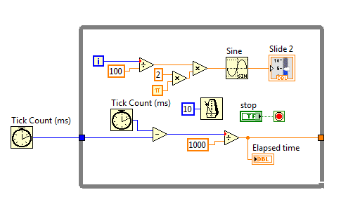
First of all, please understand this waveform generating function works. You specify a waveform (amplitude, frequency, etc.) and whenever you call the function, it returns all the wave specified points.
You can set the number of points with the #s of the info of sampling pole control. As you put the function in a loop, each itaration gives you #s number of points (1000 in your case). You always get a sine wave on your cursor because each iteration returns a different set of 1000 points (this is because of the method, the function calculates the waveform).
The easiest way to create a sine wave is using the sinus (mathematics, primary, Tigonometric, sine) function. You must use the iteration of the I of the loop counter so that the entry of the sine function. Note that the entry is in radians.
With a little math, you can easily produce and display a sinusoid at 1 Hz.
Kind regards
Adam Boros
-
Measurement of deformation of the sine wave
Hi people.
I'm trying to measure the deformation of the signal coming from a range. Its a sine wave typical that distorts the increase of entry (see attachments). I was initially just to subtract a known since the signal signal to give the difference. The fault point by point is great for this. I also try to figure out the slope over time and rapid changes of the slope would indicate the point. However, point-by-point calculation of the slope gives too much error. Is it possible to generate accurate slopes or y at - it a function that determines if a signal is not sinusoidal?
Thank you
Select this option.
For a quick visual check, you can use vi tone detection and the export of the residual signal, maybe the effective value of the residues is a nice value (THDN)
Measures of deformation of a periodic signal (in general) often made in the frequency domain and called harmonic distortion. Also, there are screws that can already do it for you. (SINAD). The level of DHT is usually used. See signal processing - wfrm measure
Your traces resemble a calibration of accelerometer ball steel 1 g for me.

-
Why my output signal is produced waves triangle when I want the sine waves
in labview I use the daq assistant to create an output voltage signal to create a sine wave. When I connect it to the opscilloscope, it reads the triangle waves. is someone can you please tell me why this is.
9172 is a chassis so I need to know the module you use, too. You should try the example:
%ProgramFiles%\National Instruments\LabVIEW 2012\examples\DAQmx\Analog Output\Voltage - Output.vi continues
It shows you how to create a waveform to generate, you could use this piece and feed in your daq assistant.
-
Is it possible to change the sine wave 'exit' a simulation device?
I work on a LV collection and analysis VI in LabView that interfaces with a CDAQ-9178 loaded with 9215 modules/a. chassis. In the Measurement & Automation Explorer, I was able to set up simulated devices that work with my code and I get the sinewave / 5 (?) standard signal noise %.
However, to really test my application, I need a slightly different sine wave with high frequency (1-10 Hz vs the)<1hz sent="" by="" the="" simulated="" device). ="" is="" there="" anyway="" to="" modify="" or="" get="" the="" simulated="" device="" to="" output="" a="" different="" wave? ="" if="" not, ="" are="" there="" any="" other="" simple="" ways="" to="" simulate="" the="" device? ="" i="" could="" write="" another="" vi="" to="" send="" out="" a="" sinewave="" but="" was="" looking="" for="" a="" more="" obvious="" or="" simpler="" solution="">
Thank you
# You need to do is call an of the generating functions of waveform instead of the DAQmx Read. Place inside a case, the declaration or the conditional structure disable is fairly simple.
-
Change the peak of the sine wave in a time interval
Hello
I had a sinusoidal signal. With peak detection, I can get its peak and after he group thus places, I can get a XY chart that indicates the time vs pics. However, all the 10s, the pic will change. I would like to show the continuous change of vertices in that graph. However, even if I extended the x-axis (time), the PIC cannot change after some determined points. What I've got, it's the ridge line climbs to a higher or lower level. However, no continuous change is displayed.
Because of the size of the data matrix? I mean, the graph updated every time after that it got a number N of data? Can I increase the number of N through buffers renovated or change N somewhere?
Thank you.
I noticed a few things: first, all displays are graphics and graphics is not the memory associated with them every time they are updating old content is completely replaced by new content. The way you describe what you want, you need a table somewhere to capture the peak each acquisition value.
Second, you don't have a count by sampling wired to the acquisition of VI. Run in this way, the read function reads however many points is available - and sometimes this counter is zero. Try a constant with 100 inside wiring the number of input samples.
Mike...
-
Measure the period and the peak value at crest of a sine wave
Hello
I am new to Veristand and Labview and I was wondering if there is the possibility to do the following:
I would like to measure the period of a sine wave that I capture from analog input of my data acquisition (SMU-6363). Apart from that, I also want to measure the value of crete to crete (Vpp) of the sine wave.
I hope you can help out me.
Thank you.
If the sine wave is of significantly higher frequency than the primary control loop can run... The best way to do it would be to put the DAQ hardware in waveform input mode and use a custom device to read the waveform and perform analyses.
an example is here: requires some labview skills
\examples\NI VeriStand\Custom analysis Devices\waveform -
transformed of Fourier of the sine and square wave return is not the frequency of the wave.
Hi all
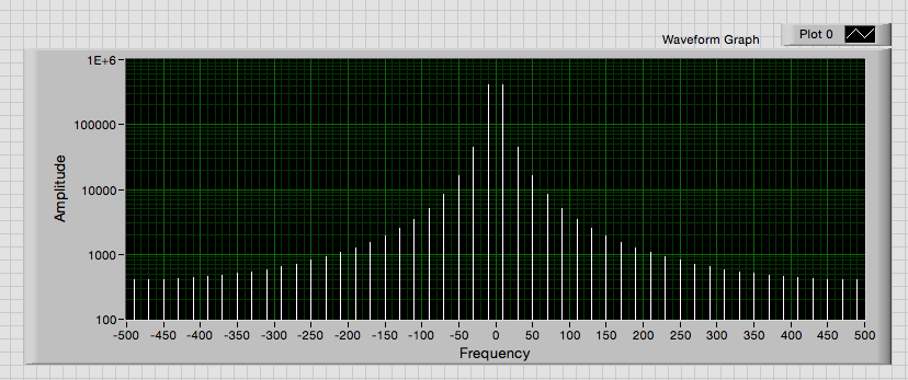
I did a few programs to determine the Fourier Transforms of the sine waves and square waves. I understand that square wave harmonics when FTed but the Harmons of the square wave is not out at the right frequency and neither is the sine wave. Any help would be appreciated. I have attached my programs, so you can take a look.
Thank you very much
M
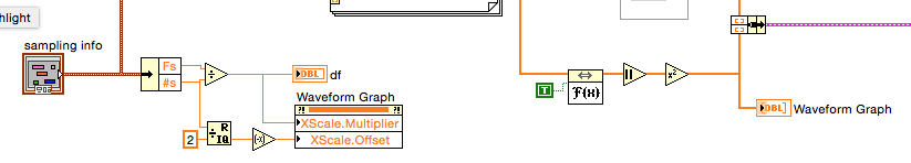
The axis of your frequency VI is missing.
Given that the data are sampled in a uniform manner, you can use a regualr rather than the graph XY Chart. Then you need not create a table of the x-axis. A property node to set the frequency axis scale multiplier and offset.
Lynn
-
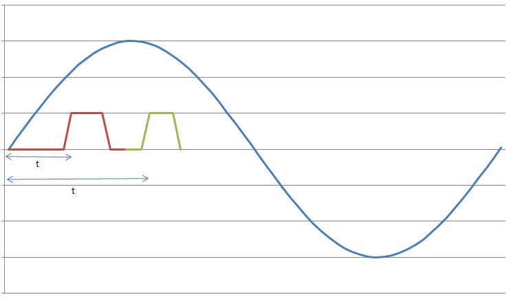
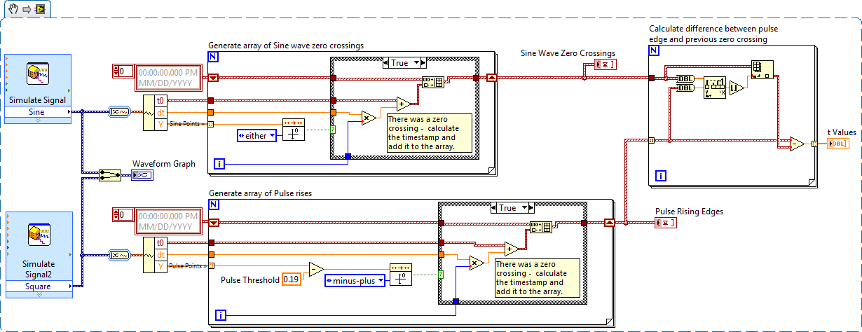
I have a sine wave of 50 Hz and a pulse of the signal on the same chart. The difference in phase between the two is between 0-90 degrees.
Now I need to calculate the time difference between (when the sinusoidal wave passes through zero volts) and (when the pulse increases). The frequency will remain about even for the two signals.
The request is for a three-phase generator. In simple terms, when the difference in time between the passage to zero of the sine wave and pulse increases increases, it means that the load on the generator has increased.
I am a novice user of LabView (version 9, 2009), maybe it's a very simple problem but I was pulling on my hair for the past few days and couldn't understand anything. Any help would be greatly appreciated. I use DAQ USB-6008 to measure these tensions and the impulse of the generator and a sensor
I have attached a jpg file (a graphic that I just did with excel to explain). The time 't' is what I'm trying to measure
See you soon
Zdzislaw
Awais.h,
For problems of this kind I recommend start writing the granular steps you would take to manually fix this problem. You can't say LabVIEW (or any programming language) If you can't succinctly describe the solution to your problem.
The I want to address this problem is to:
- find all the zero crossing points and edges on the rise
- for every rising edge find the difference between the timestamp and previous passage by zero
Here is an implementation of this algorithm LabVIEW:
-
conditional error for comparison of sine waves
Hi all
I do a small program concerning some changes in the sine waves, and later I compare to set my status. I can't get through this error. I really want to put out as Boolean so my loop condition is attached to this release. Everyone please help
Concerning
Qasim
It's called Convert Dynamic Data type and on the Express > range of Manipulation of the Signal. When you drop on the diagram to a dialog box can be displayed and giving you options regarding the type of data.
Lynn
-
Caculate phase difference between two sine waves
Hey guys
Im having problems with this. I read most of it-related topics, but none of the solutions posted helped me.
I have this small circuit and im taking a few values of voltage using my pc sound card. Data acquisition works well. As you may know, the sine wave read in Terminal resistance has a different phase compared to the dinna wave read to capacitor terminal. I tested the file VI and I can confirm it in the charts that I see out there.
I had trouble identifing the difference in phase (in degrees) between the two waves.
I would appreciate if you could help me with this. Here is my file of VI in case someone can give me some suggestions on how to calculate the difference of phase in degrees. Also, in this VI, there are some tests I did with no good result at all.
Any help will be appreciated
Hi moreins,
I changed the code, check it! I gave two solutions that somehow work to calculate the phase difference.
I would like to know if this solution works for you or not. Good day!
Sincerely,
Krisna Wisnu
-
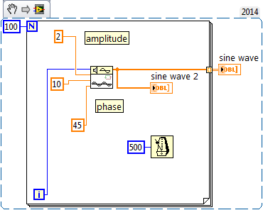
I would like to illustrate the effects of the differences on the amplitude, frequency and phase between two sine waves. I already used the sinus function and works well without phase variations. I tried to use the sine wave as planned in the signal generation VI vi, but I can't find a way to make it work. I tried to use a loop for change the entrance of samples, but does not work. I don't want to use the express vi.
Anyone out there an idea to share? Thank in advance!
Ricardo
Have you looked carefully at the example, that I told you about earlier? You can find examples in LabVIEW by going to help > find examples.
This example uses the VI of sinusoidal waveform to generate sine waves. Just look at the chart of most likely down. Look at the entries to the function and you will see how the sine waves you want do like VI.
-
How to make a sine wave in illustrator?
Hello
I started a thread earlier tonight, but I think I accidentally Pavilion as 'resolved' or something like that (I'm new to this forum). So I'll try this again. I want to know if there is a way to create a sine wave in illustrator. I managed to create a wave of cosine using the on line zig zag effect and choosing "smoothly". But I can't seem to find a good way to do a sinusoidal signal.
That's the difference for those who ask:

I want a sinusoidal signal like the image above.
Thanks for the help!
ekmanch
ekmanch,
If I (put) understand it, to create a single sinusoid full, you can:
(1) create a horizontal line 2.5 times the length of the complete sinusoid desired (or you can adapt the length later);
(2) effect > warp & Transform > Zig Zag 4 grooves by segment and Smmoths Points and height as the size (or you can adapt later);
(3) object > expand appearance.
(4) object > path > add Anchor Points;
(5) with the scissors tool cut where the sine wave starts and ends.
(6) separate if necessary and remove the end bits (and adjust the length/height if necessary).
-
cwdsp. Sine wave is where the sampling rate?
Hello
According to the method above (CWDSP. Sine wave), the parameters are the following:
(n, a, f, Phase)
n As Variant - [Input] number of samples to generate.
Amp as Variant - [Input] Amplitude of the signal that results.
f As Variant - [Input] frequency of the signal resulting in standardized units of cycles/sample.
The phase as a Variant - initial phase [output] in degrees of the generated signal. Output, the Phase is the phase of the next portion of the signal. Use this setting in the next call to this function to simulate a generator of continuous functions.We are not lack of sampling frequency?
example:
I want to generate the next sine-
FREQ = 1 kHz
sampling frequency = 10 kHz
(Number of samples) block size = 1024
Amp = 1
How will you use this function for this signal?
I think (but I'm not sure of it...) is: CWDSP. SineWave (1024, 1, 1/10, 0)
There is an example: "power spectrum". In this example, they do not mention the sampling frequency and the signal is generated as follows:
CWDSP. SineWave (1024, 1, 0, 1000/1024)
No mention of the sampling frequency.
Thank you
Hey Rafi,
Both of your assertions are correct. The frequency of de.1Hz at no time is the equivalent of what you would get from sampling equipment of a wave of 10 kHz to 1000 s/s; in both cases, you will see a cycle of the wave every 10 samples, as you are pointing out.
Maybe you are looking for
-
Re: Satellite L550 - cooling fan suddenly stopped working
About two weeks ago, I placed my laptop down on the ground. When I picked up two minutes later, there was an error on the screen that read something like "there is a problem with the cooling system, please contact your nearest centre of Toshiba. Sinc
-
How to install Vista using product from the bottom of the Satellite P200 key?
Hi all I recently had to replace my HARD drive as my P200 took a fatal error, corrupt all the data on the old HARD drive. I have no recovery at all disks, (none were provided), and I was wondering how am I supposed to do to reinstall Vista using my p
-
I have encrypted files on my backup drive. Install the user on the status of CA for access? How?
How should I keep my new user well that store the same name and all that stuff? If I can access encrypted files?
-
The Pavilion s5-1014 has an integrated sound card?
I am trying to install a program of first speech requiring an audio input through a microphone. I use Windows 7 64-bit. It installed OK but when I try to open it, a message says "can not find the media device. Check if your computer has a sound ca
-
widgets and remote content caching?
In my attempt to learn widgets, I found a behavior that's been frustrating me. According to the manual "how-to-avoid-recompilation" and running on a real device, I can't get my widget to reload external resources. In the example, I'm running, my con