fixed point conversion
How do I know how LabVIEW manages type conversions and type cast to point fixed.
In particular, I have two problems:
(1) assume I want to convert an integer signed 32-bit to a point fixed <+ ,20,20="">with the function "-fixed-point."
Of course this conversion involves a waste of bits. LabVIEW will keep the most significant bits, or those less important?
The same problem occurs if I want to convert a fixed point of data (for example <+ ,20,20="">) to another fixed point data with fewer bits (for example <+ ,10,10="">).
(2) I have a data represented with a point fixed <+ ,20,10="">and I want to cast to a point fixed <+ ,15,5="">by removing 5 whole bits and keeping the sign.
For example, I have the number - represented 1.5 in <+ ,20,10="">and I want to convert it to <+ ,15,5="">(to be noted that the two representations can express the number correctly).
How can I do such casting?
Thank you
Hi Tom,
That's a fair criticism, there are probably a few tribal knowledge implicit in the documentation. I'll give some briefing notes that might help a little:
- LabVIEW makes a distinction between the functions of conversion (aka "balls") and casts. Conversion always functions are trying to preserve the numeric value, with a handful of out-of-range values with different rounding and overflow modes. Conversions integer/integer wrap, while all other combinations round to closest and saturated by default. If the destination is FXP, you can configure the modes.
- Coercion points have the same behaviors as their corresponding conversion function.
- Type cast is not supported on the FPGA
- The fixed point to whole and entire Cast to fixed-point slur was created with use FPGA to mind cases. They are not pure bit casts, because they support extension of sign for an arithmetic scaling, as well as ways of handling overflow. I hope that the new documentation is a bit clearer on their behavior.
- Number of reinterpret is a little pure cast to numbers FXP or integer, available on digital > palette to comma fixed only under target FPGA. It simplifies the behavior by limiting the length of the input word and output is the same.
Tags: NI Software
Similar Questions
-
It is possible to specify the length of Word and whole for the fixed point data format, and if so where this work?
The module I use is a NI 9205 in a cRIO-9074 and seems to have a fixed point default data format of <+-, 26,="" 5="">, which I interpret as meaning that the data is signed, has a length of 26 Word and a length of whole number of 5. This gives a maximum of 16, a minimum of-16 and a size of minimum step of ~4.768 x 10 ^-7, that is to say 1/2 ^ 2.
Could someone please confirm that this is the correct interpretation, and also explain how it is possible to obtain a length of 26 Word when the analog digital converter / base is only 16 bits.
Best regards
amendments
-
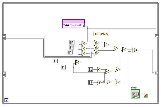
fixed point math with shift on FPGA register
It would be easy, but it's on FPGA.
Essentially, I want to do what is shown, but with fixed Point data. I also need my release of the add function to be <+,32,0>, as she goes into a generation of sine wave VI as the frequency. Basically I want just the frequency to rise slowly to "step size" at certain pre-defined rate. Is it possible to do? There must be a way I can do number table boolean then table of Boolean number, do a few manipulations to the bitwise and convert to the point type fixed I want. But I can't understand it. I also read some fixed point on NI.com unsuccessfully to operate. Frankly, fixed-point math always escapes me.
Any suggestions?

Ah, what the trial and error method will do for you.
It seems to work.

-
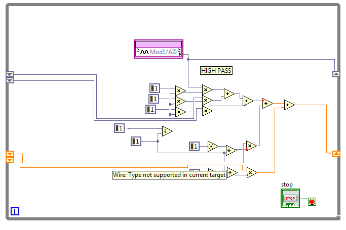
cRIO wire becomes double, but I use fixed-point
Hello world
I've been looking for examples try to understand why a thread that I use is of type double. I thought it was because the number of bits was greater than 64 bits (LabVIEW does not have 64-bit fixed point). Can someone give an idea of why this phenomenon happens? Look at the pictures below to see what is the wire which causes conflicts. Constants have the value 1 because I tried to use the minimum number of bits and the maturity of the operations were ultimately a superior 64-bit word length. If you can direct me to a link where a person might have a problem like it's ok. Thanks in advance.
When LabVIEW does not know what digital use, default usually floating-point representation. This happens in cases like this where shift registers are used and there is a mismatch as fixed-point. You can work around this by configuring the output data type of multiply that nodes. Right click on the node are multiplying, select 'Properties', then select the representation fixed-point you want in the tab "output Configuration. This will enforce the data type.
-
Table 2D-fixed points allocated to the amount of disk space!
Hello
I'm trying to create a 2D table file that will be saved on a real-time target. And should be read by my application in real time.
To create a file as small as possible I have it recorded in fixed point format. (integer 16 bits 6 bits)
The table size is 1024 X 1024 data points which is ~ 1 M data.
If I save the file to the DBL format I expect to get 8 MB (each data point is represented by b bytes) of the file - and that's what I
If I save a U16 format, I expect to get 2 MB file - and that's what I indeed.
I waited get a 2 MB file with fixed point format-, but as you can see in the screenshot - I did not!
No explanation why the checkpoint file is fixed so great?
Thank you
The FXP is 64-bit internally.
-
host vi data only appears in fixed point format
Hello
The FIFO DMA are configured as fixed point integer length 16 and with note 19. When they are acquired by DMA FIFO in FPGA entire watch and mantissa. But when acquired his watch only the integer in host and I lose mantissa. He get rounding upward? Is there a way I could get the accurate data both the mantissa and integer?
Ta
Hello
The table of fixed points in your host vi application is defined as: 33 bit word length and 33 whole bit, in this way you will be non-integer values.
You must change your configuration of fixed point. Right click on the table, select properties and change the parameters in the tab type data of select simply adapt to the source.
Hope this helps,
Paulo
-
Hello
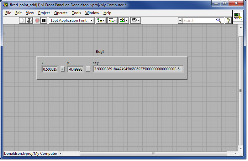
I am currently working on a project in LabView and met FPGA something weird that looks like a bug, but it could also just be me not well understand how fixed-point numbers are supposed to work. I work in LabView 2010 Pro (32-bit 10.0f2) on Win 7 Ent. 64 bit.
The problem I have is that when I try to add some numbers together I get unexpected answers, which obviously makes the code very unreliable.
For example: If you try to add 0.50002 with - 0.49998, you expect something around zero, but instead, you get like 3.99999... Am I missing something here? I saw this on several numbers around zero. Fixed points do not work around zero?
I should add that I just tried it on the local computer and not on the FPGA, but I don't see that would make a difference. The two entries are updated to 'Adapt to the entered data' and the output is "Adapt to the source", the Add function is also set to "Adapt to the source" and I tried the envelope and saturate... I also tried with fixed bits rather than adapt to the data entered on the inputs etc with no luck.
Can anyone shred some light on this please? Is it just me or is it really a bug or just as fixed-point numbers are supposed to work?
Thank you!
/ Joel
It is not a bug. If you develop the indicator displays the result, you will see that there is an exponent of-5 at the end (e-5 = 10 ^-5). So that is to say the answer is 4 * 10 ^-5 or 0.00004, which is pretty close to 0.
-
Understand the values fixed point of a NOR-9203
I have a cRIO-9073 with a NI 9203 module. In LabVIEW FPGA, the card values are returned as a fixed point. LabVIEW chosen fixed point properties are (+/-, 21-4) that apparently offers a range of (- 3.125E - 2, 3.125E - 2, 2.98E - 8), and the current card in the range 4-20 MA with a resolution of only 16 - bit. My understanding of fixed point values is only slightly, then someone can explain to me why a 21-bit value is required for the 16 - bit acquisition data?
Hi Thoric,
Sorry, it took a while to get a response to you. The necessary extra bits with fixed point representation are for the overflow feature. There is more information in the link below.
http://zone.NI.com/reference/en-XX/help/371361E-01/lvconcepts/numeric_data/#FXP_overflow
I hope that this answer to your question, but if you need more help please let me know.
Kind regards
Thomas Clark
-
Fixed points can always be controlled by Mousetrack
Thank you Jeff, it's exactly what I had to do. Problem solved!
I have another question if you don't mind. Is it possible to have a foot of characters with 'Fixed' points, and points of "Mousetrack"? I would like the character seems anchored down and stable until the moment I want to move her legs to step on and off the screen.
If you set after pass parameter to the Tracker of the mouse to hold up, it would work? You may need to move only those handful slightly initially to secure them in place first.
-
Anchor Point & Management Points conversion tool
To quote: this:
"To convert a corner point without guidelines from a corner with guidelines first, independent point slide a point of direction on a corner point (making a point of inflection with guidelines). "Release the mouse button only (don't release the keys to activate the Steering Point conversion tool), and then drag two points."
My question is:
Once you have moved from a point of direction, with the Convert Anchor Point Tool, is it possible to then move the two points of direction at the same time? Or should we use the Convert Anchor Point Tool to convert this point into a point of inflection?
How and why should I use it? I do not know; I do I just know everything about management points.
Yes, you can move the handles of direction chosen at the same time by making the scale/rotation (a tool for transformation), but you cannot move them without moving the Bézier point.
Try this
Draw, then select a circle
Select > object > guidelines handles
Use the rotation tool
-
The path segments and anchor point conversion
Once again, coming from CorelDraw background, working with paths and their anchor in Illustrator, seems me very little practice, but hey, I'm willing to learn. However, I could not find how to get this Illustrator basic functionality, and oh boy I searched a lot. So, here we go, maybe you guys can give me a hint.
Basically, in CorelDraw, anchor points can be: cusp point, smooth or symmetrical and the correspondence path segments can be lines or curves, all of these can be set by little fast individually and for me somehow normal.


Now in illustrator, I know how to use convert tool for shwitch to a smooth point to a corner anchor point or the other way around. But many times, after his conversion to a point angle, I would like to have the posibility to do one or the other line segments of a path or curve. How can I do this in Illustrator?
It is also possible to reproduce the functionality of symmetrical knot in Illustrator, which is specific for an anchor point handles, are the same length, move synchronized and always 180 deg apart.
Thank you and sorry if my questions are obvious, I can't find my energetic path in Illustrator.
I'm really sorry for this announcement.
Don't apologize. Your points are not invalid.
Fact, it's simply, Illustrator does not provide an explicit anchor type that assures the tangency between the right and a segment of the curve (your screenshot third in your initial post). Draw is done. The fact Freehand (called connector Points). No Illustrator.
Illustrator does not provide an adequate means for retrieving a single handful of anchor point. Allowing you to win almost end up disrupting the curvature of the adjacent section.
Illustrator does not constraints anchors to symmetric handles of the same length. You can do this initially convert result to slip with the tool, or (recently) click the button convert to smooth in the control panel. But even once, there no special anchor type to ensure that the symmetry continues with future adjustments.
If you continue to study carefully the differences, you will find several omissions similar and/or limitations in interface of Bezier path of Illustrator, for taken-for-granted things in other programs. For example, you cannot compel a length of handle adjustment (sliding) to the current angle. It's always been like that. The Illustrator Bezier interface is worse in their class. Too many tools; too few features.
JET
-
Proportional column width vs fixed tables (conversion of Ventura)
Hello, all! I'm busily conversion (Finally, rebuild is a better word) Lighthouse weekly newsletter of our company publication of Ventura 10 for InDesign CS4 (PC version), while learning InDesign on the fly. About half of the publication resumed with tables of prices of 1,600 price guide. I read what I can on the tables, because they are so essential to our production process, and I quickly (sometimes 15 minutes of approval of copy/final price to get the file to the printer or emailing to subscribers).
My question: am I right that there is no way to set a proportional column width in InDesign? In Ventura (for the non-Venturians there), I can set one of the columns as proportional. Then I can set the columns where I don't want the width to change as fixed and define the width of each separately (left column is 2, 11.900pp, a gutter is 0.6, etc.). Table resize all proportional columns, and the table is set up to fill the frame in which it is.
I find I have to resize the columns individually, just as the word and then try to make sure that the entire table extend beyond the frame. I also find that I can not select noncontiguous columns to set them to distribute columns evenly. Since I rarely proportional columns right next to each other, I can't use this feature, most of the time.
I want to just make sure that I only am not missed something as a novice to InDesign. In the example below, the columns 1, 5, 6 and 10 are proportional (in color, so they can be easily seen here). Then I size just the width of these columns, and everything else set proprtionally with a width equal to fill the frame. Any way to do with InDesign?
Thank you! -Nancy

Unfortunately, no. Miss me also the proportional column width.
As you discovered, Indesign does not limit the width of the table in the width of the frame. So even if there was a setting to "fill the remaining space", it wouldn't work because Indesign is not a way to know what is the remaining space.
Ken
-
Why did in Flight Simulator x with the expansion pack Microsoft, each plane has the cockpit view with all the templates and everything for this particular
aircraft. but in Microsoft Flight, I own several aircraft there is no cockpit view, and if you want to fly from the cockpit, you feel like you are flying in
flight with no noise of the aircraft, and there is no realism with some aircraft. I want to know why you done guys and why it can not
be fixed. My P51s should have a cockpit view, they do in my other flight sim. What is the difference of Microsoft Flight that you guys make with
several aircraft Microsoft Flight is supposed to be more realistic than any other Flight Simulator you ever turned off, so make and deliver cockpits
these planes so that it is as real as this. That's what many of us think Microsoft Flight was going to be, it has never been the most realistic Flight Simulator.
Hello
What version of the Windows operating system is installed on the computer?The question you posted would be better on the support forum for Microsoft Flight Simulator. I suggest you to post the question on the following link: http://www.microsoft.com/Products/Games/FSInsider/community/Pages/default.aspxYou can also check out the link below which gives you all the information on Flight simulator X and how to fix the problem and let us know if this helps you to solve the problem.
Here is the link: http://support.microsoft.com/gp/cp_flightsim_master#tab0 -
How to configure a button with alignment fixed points on a logorithmic scale?
My question is quite simple, but after rooting in the button/gauge proteries, I can't find a way to do what I would like to:
I would like a simple button with 4 possible values control: 0.0125,0.125,1.25,12.5
I would like that they also spaced and I want the button to engage only in one of these four values
I can get it at least to the point of having four values there by placing arbitrary markers (scale-> add the marker), but I can't figure out how to align them, or even if it is the way of Paris to follow on that.
Thank you!
See example LV86 attached. Open the Properties dialog box for the button for more information on its configuration.
-
JQuery Code does not (positioning Nav at a fixed point)?
Hello allows so just cut to CACE,
This code works outside the edge but doesn't work in edge...
.bind $(window) ("scroll", function () {}
SYM.$("arroworb"). AddClass ('fixed');
});
The object I want to keep in its place at all times, even if the scroll bar is moved has the ID of the div of the arroworb...
I have no idea what I'm doing wrong, but yes, the code works it comes when implemented edge
My guess would be the window or the blind has something to do with it works do not, but I have no idea how solve this problem.
Any idea?
Thanks in advance!
Hey there,
Where is the class "fixed"? When using addClass, jQuery (and Animate) provides that a css class.
It is perhaps useful, however: a similar question came a few days ago. Check this thread:
http://forums.Adobe.com/message/5435811#5435811
HTH,
Joe


Maybe you are looking for
-
Cannot download information because cookies are diablrd. This happenea, right after I downloaded the software update.
-
Product key required for system restore in XP?
I need to restore my laptop and having records now, but the Windows XP disc wants a product key and I don't think I have, or I do? Can someone clue me everything I need to do at this time? Thank you!
-
Final need Defrag using information
I know how to access Windows defragmentation. I know how a C:\ Defrag invites manually. I know how to set an automatic defragmentation schedule. I know that defrag will only work while it is inactive. What I don't know: (1) automatic annex is of (pre
-
Update blackBerry Smartphones don't 8900 a.231
My 8900 is running 4.6.1.133. When I try to upgrade the operating system by using the application in DM 5.0 loader, he recognizes la.231. When I select and click on next, in the "Update the summary" pane, he says "no software update is required for y
-
I am a paid subscriber of Adobe, but I can't save my pdf as a word document. I looked at the help and there is no record in the Word icon in the corner right as they say, there should be. What I am doing wrong?