[FlexRIO] Start-up to synchronize several clocks sample
Hello
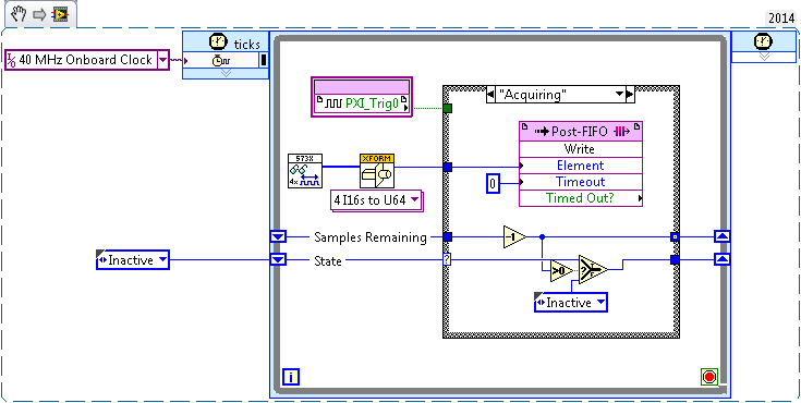
I tried before, two different (SMU-7962R + OR-5734) FlexRIO card reading in the '40 MHz Onboard Clock' or 'PXI_Clk10' areas of clock. Trigger has been achieved by simply looking for a rising edge on PXI_Trig0:
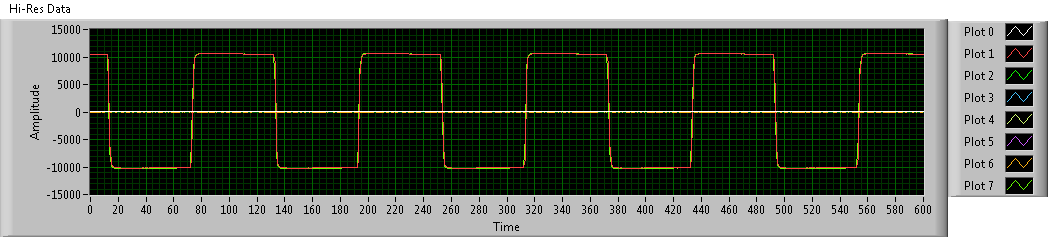
This produces seeds, but there has no inclination (or constantly tilt at least) between the two FlexRIOs - I sent a pulse train duplicated in the two cards, and the triggered-acquired waveforms were still at the stage:
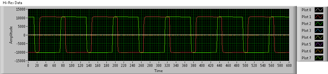
To avoid problems, I went to examples of clock (IO Module clock 0). Unfortunately, the clocks of the sample between the two FlexRIOs had nothing in common, so the acquired waveforms have been is out of phase. Worse still, the phase difference changes with each release:
Looking at the implementation of the library of the synchronization of the FIDL, the classic technique for synchronization of multiple cards FlexRIO seems to be built around synchronization master-slave (my observation is correct?). I was wondering: is there a way to simply share a sample clock shared between cards (like what the 40 MHz embedded clock was doing before), as described in http://www.ni.com/white-paper/11369/en/ ? (I think I understand the disadvantages associated with sample clock synchronization, but I'm willing to try for now).
Thanks in advance!
Hi JKSH,
Page 9 of the Manual 5734 described the different synchronized methods that can be used the 5734. You can synchronize either sample clock of each module to a clock available through your chassis backplane (for example, DStar_A) by allowing the IOModSynClk in 5734 properties (available the Details category) or use an external clock through the Clk port on the module. Activation of IOModSyncClk is probably the best approach and will lead by examples of clock on each module e/s being PLLed on the clock of the town - which must synchronize the clocks of the two sample together.
Let me know if you have follow-up questions.
Kind regards
Tags: NI Hardware
Similar Questions
-
Reference clock synchronization and clock of sampling (not LabView but Daqmx, Sync and C)
Well, I found an example that resemble what I wanted... in LabView: http://zone.ni.com/devzone/cda/tut/p/id/9308
Now the question is all about timing of the timestamps and sample:
Here is a list of ficelleStringString ficelleT of what I called...
DAQmxCreateTask
DAQmxCreateAIVoltageChan
DAQmxSetRefClkSrc (used NISYNC_VAL_CLK10 = "PXI_CLK10")
DAQmxRegisterEveryNSamplesEvent
niSync_init (used a PXI-6682)
niSync_SetAttributeViInt32 (used Terminal = NISYNC_VAL_PXISTAR0 and NISYNC_ATTR_1588_TIMESTAMP_BUF_SIZE = 3000)
niSync_CreateClock (used Terminal = NISYNC_VAL_PXISTAR0)
niSync_EnableTimeStampTrigger (used Terminal = NISYNC_VAL_PXISTAR0)
Now this list makes me able to create a timestamp every time the clock triggers a RISING edge...
Now how to synchronize these timestamps are useful for my sample? (I mean I need to sync my calendar with the PXI_CLK10 card) because for now prices will not match the sample rate.
ALSO... a little weird...
some of my cards will accept DAQmxSetRefClkSrc but others must use DAQmxSetMasterTimebaseSrc.
Now I can't use DAQmxSetMasterTimebaseSrc with PXI_CLK10... no idea why...
So, how did I would synchronize THESE cards...
Alright I could totally be wrogn with my approach, but I'm new with stuff of OR and using C isn't exactly the best documented piece of the NC.
Thanks in advance,
SEB
Thus,.
We have the same clock sampling for all of these devices, but we are not PLL'ing with the card of the S series, we cannot guarantee that they will all be in phase. However, given that all of these devices would be based on the same reference clock, we would not drift when we started the task. Would this work?
An alternative is to use the new X-Series card, which can also do a simultaneous sampling, but I don't know if it is feesible within your application.
-
Synchronize several USRP using Octoclock
Hello community!
I'm trying to synchronize several Ettus USRP N210 using Octoclock. I send you a short tag to a USRP to each set second (using the timestamp on board), the other USRP choices until the tag and display the time. I put the clock at PpsIn two USRP source by using the node properties of niusrp, but it seems the two USRP to use even their internal clock: I see a fraction of a second relatively fixed the RX once it picks up a lighthouse and this fraction of a second does not change if I put the clock to internal or ppsin source. I don't know if this is the correct way of sync USRP external reference because I'm quite new to Labview Comms, anyone have any ideas? Thank you very much!
Hello Maxcy,
Welcome to the community!
I highly recommend looking through aid NOR-USRP > Programming Reference > document MIMO synchronization. This will help you understand the synchronization.
Synchronization requires two components, a shared time base and trigger to start. In this case to share the time base, you use synchronization and synchronization of the USRP properties reference to set the frequency to RefIn reference and the Source of the time base to be PPSIn. You will need to wire the system as Figure 9 in the following Document Ettus:
http://www.ettus.com/content/files/KB/mimo_and_sync_with_usrp_updated.PDFIn order to share the relaxation from the beginning, we want to use the time to start to set up to be in 1 second increments. More important, you want to reset timers USRP onboard all USRPs at the same time. This is done using the Set Time VI and ensure that the change is applied to the next edge PPS (together the entry timestamp apply 1). This will require the TX and RX both be started and configured in the same second on the other. For testing purposes, I have recommended to configure the RX and TX within the same VI. This will benefit of innate parallelism of LabVIEW and ensure that both are started at the same time.
With synchronization, above all there will be a random amount of phase constant offset between the channels, as shown in figure 6 of:
http://www.ettus.com/content/files/KB/mimo_and_sync_with_usrp_updated.PDF
This could be responsible for your consistent fractional offset. These needs to be processed signal to ensure alignment.I hope this helps.
Kind regards
-
Problem with congregate and synchronization of clocks
I have connection problems of my laptop and desktop at a home group. When I look at the clocks, the office is always a few seconds faster than the laptop and somewhere I read that the clocks must be synchronized for the home group to work.
What's odd about all this, I just did a fresh install of Windows 7 on the laptop a few days ago group home worked fine for about a day, then he stopped.
I tried to use the time Internet sync to synchronize the clocks on the desktop and laptop. I used 4 servers of different times, but whenever the real-time is a couple of seconds between the office and cell phones. Nothing I've tried will get them to sync.
Any help that you could give to fix this problem would be greatly appreciated.
Hi Profrock,
First of all, try to run homegroup troubleshooter built into windows 7 and check if it helps solve the problem of residential group on your computer. Access the link below and follow the steps to run the troubleshooter in homegroup. http://Windows.Microsoft.com/en-us/Windows7/open-the-HomeGroup-Troubleshooter
If the problem persists, you can try to start the computer in safe mode with network and check if you can access the homegroup. To boot to the desktop in safe mode with network keep tapping key F8 during restart. Once you see the option to start it in safe mode with select network and press ENTER.
Access the link to learn more about how to start the computer in safe mode: http://windows.microsoft.com/en-US/windows7/Start-your-computer-in-safe-mode
You can also try to temporarily disable the security software of the computer and check if you can access the homegroup. If you are able to access, you can contact the manufacturer of security software and check if you need to change the settings. Later, re-enable the security software.
Also note that there is no case of residential group doesn't work not based on the clock.
I hope this helps. Let us know the results.
Thank you and best regards,
Srinivas R
Microsoft technical support.
Visit our Microsoft answers feedback Forum and let us know what you think.
-
By dividing the time base clock sample by N, we're the first sample on pulse 1 or pulse N?
I use an external source for the time base a task of analog input sample clock. I'm dividing down by 100 to get my sample clock. Is could someone please tell me if my first sample clock pulse will be generated on the first impulse of the source of the base of external time, or about the 100th?
I use a M Series device, but can't see a time diagram in the manual that answers my question.
Thank you.
CASE NO.
CERTIFICATION AUTHORITIES,
I don't think it's possible to use the sample clock of 3 kHz on the fast map as the time base clock sample on the slow map and get the first sample to align. The fast card can enjoy on each pulse signal 3 kHz, while the slow card will have to meet the requirement of the initial delay before he can deliver a sample clock. If you turn this initial delay a minimum of two ticks of the time base, the slow card eventually picking around the edges of the clock 2, 102, 202, etc.. You can set the initial delay for 100, which means that the slow card would taste on the edges, 100, 200, 300... but you wouldn't get a card reading slow on the first edge of your sample clock.
Hope that helps,
Dan
-
Hi ppl,
I have a question for you.
I have a very similar to the attached picture circuit. also you can find here (http://zone.ni.com/devzone/cda/tut/p/id/3615#toc4 , fig.2) I write some data on analog channels out and then I collect the data in the time loop. I don't understand what exactly is happening when I write the data in the buffer. Let's say I have a table of 2D 2-lines and 62500 columns that I want to write in the output analog channel, then read in the analog channel. I do not understand the meaning of the sample clock. (I read on operations 2 devices simultaneously and blah blah blah). What should be the sample clock frequency in the August channel and the channel of the ain and the number of samples per channel in the ain daqmx channel when I want to collect data? (http://zone.ni.com/devzone/cda/tut/p/id/2835; reading the data in example labview). My problem is that I do not understand what is happening when I load the August channel with data buffer; for example I put the sampling clock rate: 1000; meaning he will write each s 1000 samples of 62500 samples until the end of the samples; all of these samples that I drove from my out channel voltage piezo-beam-scanning engines. which means that each s piezo motors will get 1000 samples of tensions? now, I want to measure. should number of samples in the playback channel I put? I put my daqmx reading in the while loop. Let's say I put 100 Samper useful/channel. so, each itteration in while loop it will read the 1000 samples/channel buffer. How will I know that the buffer is already full with 1000 samples when ain channel tries to read?
The process is therefore more; correct me please if I'm wrong. The sample clock will define us the buffer data rate. For example, I load the 2D matrix: 62500 2rows columns; It will load in the buffer and then there are these samples at the August channel of the rate defined in the clock sample string? Then I want to read from the channel of the ain. What sampling clock frequency should I set for the channel of the ain? If the sample clock rate for the playback channel sets the buffer? for example (I put it there 1000 samples/s; meaning it can read 1000 samples per second?) then what the number of samples should be in the read daqmx channel in the while loop?
Please clarify me this point, I'm confused...
Hi dimani4,
There is a very comprehensive document that answers your questions. You can find this document here.
This article explains the operation of the sample clock frequency and the DAQmx Read reading samples. Quoting the article: "On the hardware side, the Schedule VI DAQmx determines the flow rate of the device/sensor data at the hardware buffer on the data acquisition card.". Here is the 'Timing VI' the sample clock. Then he also explained that "on the software side, the reading VI DAQmx determines the transfer of the data of the buffer material in the software". "." It is making reference to the samples to read the reading VI DAQmx.
I hope this information specific to your questions.
-
Synchronize the clocks of 2 PCI cards for analog inputs with e/s digital reference
I'm trying to synchronize the clocks of reference of 2 PCI cards so that the analog inputs are synchronized. However, my appilcation has also digtial e/s on two cards, and who apparently made the mistake DAQmxErrorResourcesInUseForRoute_Routing. This discussion describes a similar problem, but the solution was to just put the reference clock to the slave device, who had no other tasks running on it, so what mine does.
Is there way I can synchronize the clocks of refernce without interfering with the digital I/o?
Thank you!
PS: My application is in C++.
The reference clock is really a lower-level component that is shared by all resources on a given device. All tasks on a given device must use the same reference clock. So if you use DAQmxSetRefClkSrc for a task, you can use it to set the same value for your other tasks.
Best regards
-
synchronize the clock of your computer with your local time?
synchronize the clock of your computer with your local time?
Windows 7 must be configured by default to set his time using windows.time.com as an NTP server. Double-click the clock in the taskbar, and then select the time tab Internet. A source of time NTP is configured?
Brian Tillman [MVP-Outlook]
-
I am a customer of Adobe since start. I buy several years of 4 licenses of Adobe suite CS4. How can I up grade to CS6 now?
You can buy it at the price high or move to creative cloud.
-
Problems of synchronization of the sample clock with a frequency of a PXI-6229 counter!
Hi all, I'm having some problems with the synchronization of a frequency meter connected to a liquid flow meter (sensor only have 1 open collector output) with the sample of a PXI-6229 map clock. Someone there willing to give me a little help here would be appreciated?
The problem is that the reading of the meter in the whole loop blocks until the time-out period.
Suggestions for an alternative approach would be too good...

Source code attached.
BR,
/ Roger
It sorted another way!

-
synchronization and clock cDAQ-9174
I have a cDAQ-9174 with chassis
HAVE - 9205 OR 9205
HAVE - NOR 9219
DIO - OR 9401.
"NOR-DAQmx allows the on-board clock routing synchronize acquisition or generation of data transactions. A single sync signal or a trigger can be shared between multiple operations on the same device to ensure that the data are synchronized. These signals is shared by the simple signals routing functions that allow connections integrated hardware DAQ. " (from http://zone.ni.com/devzone/cda/tut/p/id/6829)
When I check the itineraries device in MAX tab' for chassis and c modules individually, I found many clocks with the Green blocks (direct Route). "Once a physical connection is determined, the NOR-DAQmx driver lets the user quickly and easily use this connection to synchronize operations".
Now my question is how do you choose among these clocks available. What is the frequency of these clocks? The highest frequency the better? What is the difference between /Ctr0SampleClock, /Ctr0InternalOutput, /Ctr0Source, /Ctr0A?
For example, why well/Dev1/I/SampleClock or Ctr0InternalOutput or of others, especially as a source for the .vi DAQmx Timing (sample clock)?
Thanks a lot for your help
Bing
Concerning
Hello NCLbingji,
I think you mix instructions from the manuals of different material. The link you posted refers to the synchronization of several separate devices, while your cDAQ with its modules really is like having one device almost. You will find more relevant information in your manual of cDAQ chassis. For multiple devices, you indeed have a "physical connection", but with the cDAQ is not necessary. You set up these connections in the software in any way, and this should get the routing sorting at the driver level.
Try to identify which channel will be your a 'primary', the one driving all others and synchronization, the value then asked SampleClock of this string as the rest (DAQmx Trigger.vi) trigger ('secondary') channels, then start all 'secondary' jobs and finally start your "primary" task This will trigger all tasks at the same time. Take a look at the attached picture, which is another application that I worked on, but I think this will help.
I hope this helps.
Kind regards
Michael S.
Technical sales engineer
NEITHER UK & Ireland -
Best way to synchronize several FPGAs
I have several PXI-7833R FPGA and I need all the AIs to be sampled at the same time (through all FPGA). As I taste all the individual channels to HAVE, I have data (write to the DMA) buffer, scan it and are looking for a trigger defined by the user in a different loop. Once I discovered this in a single channel, I save all FPGA data. Regarding the timing of sampling, I had started, to an FPGA, to send a signal on the PXI trigger line to tell others to try, but I guess that it does not sync. If I founded the ensemble of distinct FPGAS screw off the clock, PXI, how synchronize loops to the sample to the same clock time?
Thank you
Hello
There is a very good example comes with FPGA LV named 'Master-slave of RIO - R Series.lvproj'. Just use the Finder for example to open it.
It shows how to use the lines of PXI trigger for synchronization of the different measures on multiple FPGAs.
Hope this helps,
Christian
-
Hi, we intend to use the PCI-6071E to measure signals of tension of two photodiode arrays (PDAS). Detailed implementation is the following:
Mode of operation: input analog, acquisition continues, external clock of sampling/analysis (rate ~ 100KS/s), external start trigger
Software: C++ based on NI-DAQmx
Start by the example code "ContAcq-ExtClk - DigStart.c.
We intend to use a single analog channel for PDA. Each PDA sends a series of singals trigger (which will serve to 6071E as sample clock), an edge from low to high for each pixel. The experience is configed such that most likely, we can use the same start for the two entries of PDA, but their clocks in the sample may have a relative delay (typically a few microseconds). We certainly prefer to acquire the data of each input channel with respect to his own sample clock.
Is it possible to do? How?
Our initial estimate is to schedule two TaskHandlers, each with its own sample clock configed (maybe start trigger as well) and start/play/stop almost at the same time. This seems reasonable? If so, our ultimate goal is to work with two more PDA (a total of 4). What is the limit of the number of sample clock so all acquisitions are made sinmutaneously?
Thank you for your comments in advance and your solutions.
Kunyan
Hello Kunyan,
Unfortunately, with the 6071E you only PFI monotube (PFI 7) for the sample external clock use, as a single line PFI to HAVE start the use of the trigger. You can see 6071E specifications to see these lines. You will most likely run all your PDA out of the same sample clock and starting to trigger, unless you do not want to use several DAQ cards. I hope this helps.
Kind regards
-
Synchronize the clocks of PCI I / AO with multiple AI in parallel
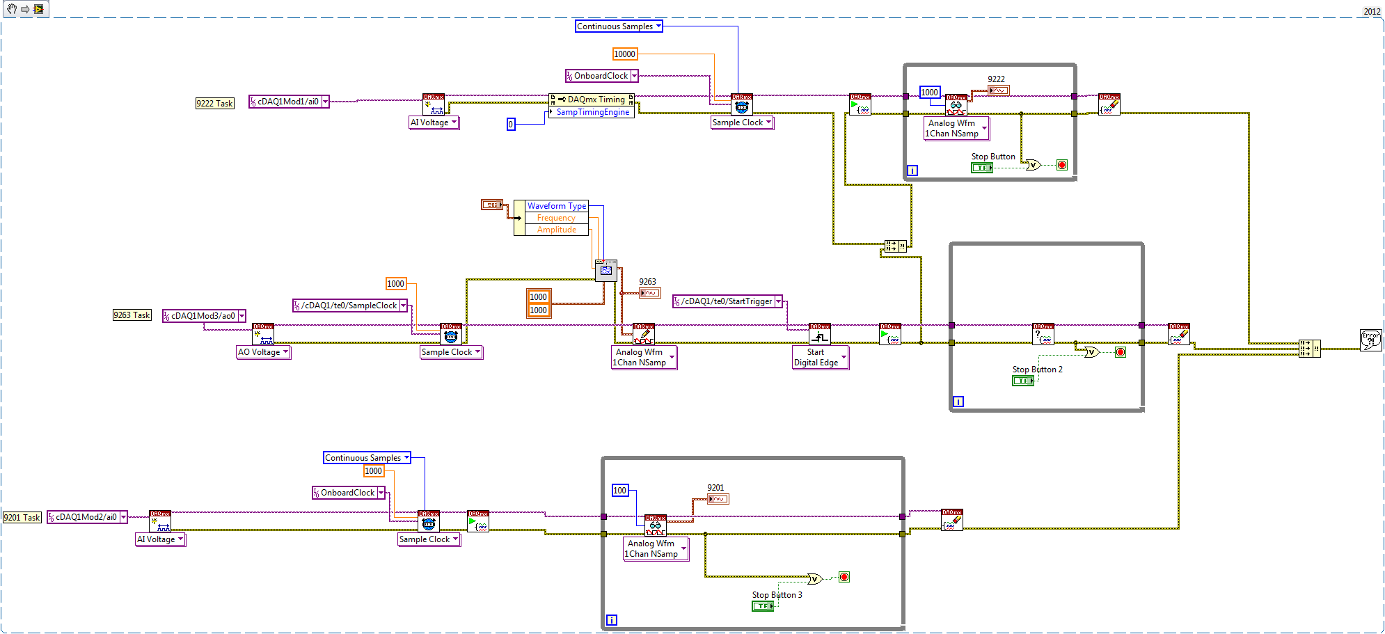
I want to synchronize my HAVE and AO to run on the same clock and have my AO beginning with a relaxation from the beginning of IT. All works beautifully except when I have another process running in parallel. I use the cDAQ chassis 9178 and I have a low resolution HERE (9201) that runs in the context of monitoring for alarm conditions. I want to run in parallel to my DAQ vi.
In the vi DAQ begins AI (9222) and triggers the AO (9263), the AO clock is referenced to Dev1/AI/SampleClock and start trigger is referenced to/Dev1/I/StartTrigger
The problem seems to be that if the 9201 collects data HAVE then my AO is actually running at that frequency of clock instead of the 9222 (since the 9201 is always launched in the background, the OD has seen this first)
How can I tell the AO (9263) to run with the AI 9222 clock and trigger rather than the AI 9201? I think that I do not understand how the chassis works with modules...
Gracias.
Hello Telleurium,
The quick answer is call specifically on the timing engine and relaxation of timing engine. This will ensure that the 9263 and the 9222 are synchronized. Please take a look at the example below what I call specifically on the timing engineof teo.
A more detailed explanaiton of what happens is that the 9201 seizing first the timing of AI engine (which means that it is now associated with the AI and AI trigger sample clock) so you see the 9263 is synchronized with the 9201.
Best regards
Izzy O.
Technical sales engineer
National Instruments
P.S. on further notice, that it would probably be easier to point the 9201 on a different timing engine.
-
Starting point for the signal clk sample
I am currently trying to synchronize my PXI-7344 Controller with my hardware DAQ-PXI-6221. The devices are connected through 1050 PXI/SCXI chassis.
I wrote a program on board pending a signal RTSI and then making a capture high speed. The data is buffered in memory and then transferred to the PC in chunks.
To synchronize this data with my DAQ data, I want to export the sample clock in the RTSI bus. My question is: the sample clock start sending signals RTSI after that I prepared and booked the task (the sampling frequency is known) or these signals do not appear before you actually begin the task?
In the latter case, it would be much easier to merge the data because the two devices were producing the same amount of samples.
Concerning
André
Hello Andrew,.
Clock signals are not exported through the RTSI bus, until the task starts unless the trigger is configured. In this case clock signals will not be sent until the start trigger is received.

Maybe you are looking for
-
Since firefox upgradeing 11 firefox 14 used Chinese translation simplified
When I was using Firefox 11 and all of the updates in just 11 series when I used to go on sites like postal tracking from China (17track.net) she is part English and Chinese. The Chinese parties have been automatically translated into English. Since
-
Equium A60 - 199: ITunes and Mat * a UJ - 830 s (error 4280)
I can't burn CDs on my laptop. This has never before been a problem, but recently, no matter what type of burning software I use, I can't burn it to a cd. I am currently using ITunes version 6 and after the burning process starts my computer ejects t
-
OK, I have a HP Pavilion a6010n PC. Now I have Windows Vista Home Premium.Now can I remove vista and put it back in Ubunu operating system? I bought the recovery for the computer disk. Or do I just run it Ubuntu along side windows? I have Ubuntu here
-
Driver Microsoft Bluetooth Laser mouse
Equipped with Vista... Mouse not recognized Bluetooth... It is a Microsoft 5000 bluetooth mouse...
-
jQuery is the substitution of the JS validation
HelloI use this JS validationJavaScript form validation: fast and easy!and by itself, it works wellbut also I use jQuery with shapes and it seems to be on the validation of riding and fair treatment in the formQ: How do I put in place if form jQuery